PMR 2-LC (Option) - SES Combustion AB
PMR 2-LC (Option) - SES Combustion AB
PMR 2-LC (Option) - SES Combustion AB

Create successful ePaper yourself
Turn your PDF publications into a flip-book with our unique Google optimized e-Paper software.
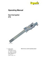
Betriebsanleitung für<br />
Operating Instructions for / Instructions de service pour<br />
Antriebe der Baureihe NL / <strong>PMR</strong> 2-<strong>LC</strong> (<strong>Option</strong>)<br />
Actuators, series NL / <strong>PMR</strong> 2-<strong>LC</strong> (<strong>Option</strong>) / Actionneurs serie NL / <strong>PMR</strong> 2-<strong>LC</strong> (en option)<br />
BA 15.4.02/0817<br />
NL<br />
NL + <strong>PMR</strong> 2-<strong>LC</strong> (<strong>Option</strong>)
Inhaltsverzeichnis<br />
Gültig für Baureihe NL<br />
Haftung ................................................................4<br />
Sicherheits-/Montagehinweise ...............................6<br />
Hinweis Schutzart ...........................................9<br />
Ex-Zone 2 und 22 (<strong>Option</strong>) ...........................10<br />
Beschreibung ......................................................12<br />
Elektrischer Anschluss ..........................................13<br />
Wegschalter ........................................................17<br />
Potentiometer (<strong>Option</strong>) .......................................19<br />
Stromausgang (<strong>Option</strong>) .......................................20<br />
Handrad .............................................................21<br />
Transport/Lagerung/Stillstandzeiten....................22<br />
Technische Daten ..........................................23<br />
<strong>PMR</strong> 2-<strong>LC</strong> (<strong>Option</strong>) .......................................24<br />
Beschreibung ......................................................25<br />
Elektrischer Anschluss ..........................................26<br />
Schaltplan ...........................................................27<br />
Platine <strong>PMR</strong> 2-<strong>LC</strong> ................................................29<br />
Allgemeine Hinweise ...........................................30<br />
Programmierung ................................................31<br />
Technische Daten ...................................39<br />
Table of contents<br />
Valid for NL series<br />
Liability ................................................................4<br />
Safety/Installation Instructions ..............................6<br />
Types of protection .........................................9<br />
Ex-Zone 2 and 22 (<strong>Option</strong>) ..........................10<br />
Description .........................................................12<br />
Electrical Connection ............................................13<br />
Position Switches ................................................17<br />
Potentiometer (<strong>Option</strong>) .......................................19<br />
Current output (optional) ....................................20<br />
Hand wheel .......................................................21<br />
Transport/Storage/Downtimes ............................22<br />
Technical data ..............................................23<br />
<strong>PMR</strong> 2-<strong>LC</strong> (<strong>Option</strong>) .......................................24<br />
Description .........................................................25<br />
Electrical Connection ............................................26<br />
Wiring diagram ..................................................27<br />
<strong>PMR</strong> 2-<strong>LC</strong> board .................................................29<br />
General notes ....................................................30<br />
Programming .....................................................31<br />
Technical data ........................................39<br />
Table des matières<br />
Valable pour la série NL<br />
Garantie ..............................................................4<br />
SPrescriptions de sécurité et de montage ...............6<br />
Information Classe de protection ....................9<br />
Zone-Ex 2 et 22 (en option) ........................10<br />
Description .........................................................12<br />
Connexion électrique ..........................................13<br />
Interrupteurs de course ......................................17<br />
Potentiomètre (en option) ..................................19<br />
Sortie de courant (en option) ..............................20<br />
Roue à main (en option) .....................................21<br />
TTransport/Stockage/Temps d’arrêt ....................22<br />
Caractéristiques techniques .........................23<br />
<strong>PMR</strong> 2-<strong>LC</strong> (<strong>Option</strong>) .......................................24<br />
Description .........................................................25<br />
Connexion électrique ..........................................26<br />
Schéma de câblage .............................................27<br />
Platine <strong>PMR</strong> 2-<strong>LC</strong> ................................................29<br />
Avis généraux ....................................................30<br />
Programmation...................................................31<br />
Caractéristiques techniques .....................39<br />
Baureihe NL 3
Haftung<br />
ARIS Antriebe/Regler sind ausschließlich für den<br />
industriellen Einsatz konzipiert.<br />
ARIS Antriebe/Regler werden vor der Au slieferung im<br />
Werk geprüft. Die endgültige Funktions über prüfung muss<br />
jedoch im Gesamtsystem von qualifiziertem technischen<br />
Personal vorgenommen werden.<br />
Die ARIS Antriebe und Steuerungen GmbH übernimmt<br />
keine Haftung für eventuelle Produktionsfehler und<br />
daraus resultierende Schäden oder Folgeschäden,<br />
nachdem der Antrieb/Regler überprüft, eingebaut und<br />
für funktionstüchtig erklärt wurde.<br />
Die ARIS Antriebe und Steuerungen GmbH übernimmt<br />
insbesondere dann keine Haftung für eventuelle<br />
Produk tionsfehler und daraus resultierende Schäden oder<br />
Folg eschäden bei unsachgemäßem Einsatz des Antriebs/<br />
Reglers, wenn der Antrieb/Regler nicht ausreichend<br />
innerhalb eines Gesamtsystems getestet wurde, oder<br />
wenn während eines ersten oder weiteren Tests Fehler<br />
festgestellt wurden und der Antrieb/Regler nicht sofort<br />
außer Betrieb gestellt wurde.<br />
Insbesondere ist darauf zu achten, dass durch den Einsatz<br />
von ARIS Antrieben/Reglern keine Sach- bzw. Personenschäden<br />
entstehen.<br />
Liability<br />
ARIS actuators/controllers are designed solely for industrial<br />
application.<br />
ARIS actuators/controllers are thoroughly tested in factory<br />
prior to delivery. However, the final operational test<br />
as part of an overall system must be performed by qualified<br />
technical staff.<br />
ARIS Antriebe und Steuerungen GmbH does not assume<br />
any liability for possible defects of fabrication or any<br />
damage or consequential damages resulting from it, once<br />
the actuator/controller has been checked, installed, and<br />
approved for operation.<br />
In particular, ARIS Antriebe und Steuerungen GmbH does<br />
not assume any liability for defects of fabrication or<br />
any damage or consequential damages resulting from<br />
it in case of inappropriate use, insufficient testing of<br />
the actuator/controller as part of an overall system, or<br />
if deficiencies have been detected during the initial or<br />
further tests and the actuator/controller has not been put<br />
out of service immediately.<br />
Particular care should be taken to avoid personal injury<br />
or damage to property when operating ARIS actuators/<br />
controllers.<br />
Responsabilité<br />
Les actionneurs/régulateurs ARIS sont exclusivement<br />
conçus pour une utilisation industrielle.<br />
Les actionneurs/régulateurs ARIS sont contrôlés en usine<br />
avant leur livraison au client. Le fonctionnement final doit<br />
toutefois être testé dans l’ensemble du système par un<br />
personnel technique qualifié.<br />
La société ARIS Antriebe und Steuerungen GmbH<br />
n’assume aucune responsabilité pour d’éventuels vices de<br />
fabrication, ni pour des dommages directs ou consécutifs<br />
en découlant après que l’actionneur/le régulateur ait<br />
été vérifié, monté et déclaré en parfait état de fonctionnement.<br />
En particulier, la société ARIS Antriebe und Steuerungen<br />
GmbH n’assume aucune responsabilité pour d’éventuels<br />
vices de fabrication, ni pour des dommages directs ou<br />
consécutifs en découlant en cas d’utilisation incorrecte de<br />
l’actionneur/régulateur lorsque celui-ci n’a pas été testé<br />
suffisamment au sein d’un système global ou lorsque des<br />
erreurs ont été constatées lors du premier essai ou d’un<br />
essai ultérieur et que l’actionneur/le régulateur n’a pas<br />
alors été mis immédiatement hors service.<br />
Il faut surtout veiller à ce que l’emploi des actionneurs/<br />
régulateurs ARIS ne provoque pas de dommages matériels<br />
et corporels.<br />
4 Baureihe NL
Haftung Liability Garantie<br />
Bei Nichtbeachtung der Betriebsanleitung sowie<br />
unsachgemäßer Handhabung erlischt die Garantie.<br />
Diese Anleitung darf ohne vorherige Zustimmung der<br />
ARIS Antriebe und Steuerungen GmbH weder im Ganzen<br />
noch in Teilen kopiert, fotokopiert, reproduziert,<br />
übersetzt oder in irgendeine elektronisch oder maschinell<br />
lesbare Form gebracht werden.<br />
Diese Anleitung kann ohne Vorankündigung geändert<br />
werden.<br />
Copyright © 2006, ARIS Antriebe und Steuerungen<br />
GmbH<br />
The guarantee is void in case of non-observance of the<br />
operating instructions or inappropriate handling.<br />
These operating instructions may neither be copied,<br />
photocopied, reproduced, or translated nor be converted<br />
into any electronically or mechanically readable format,<br />
whether in full or parts there of, without the prior written<br />
consent of ARIS Antriebe und Steuerungen GmbH.<br />
The present operating instruction is subject to change<br />
without notice.<br />
Copyright © 2006, ARIS Antriebe und Steuerungen<br />
GmbH<br />
La garantie devient caduque en cas de non-observation<br />
des instructions de service et de maniement incorrect.<br />
Ces instructions ne peuvent être copiées, photocopiées,<br />
reproduites, traduites ou être mises sous une forme lisible<br />
par moyen électronique ou mécanique, complètement ou<br />
en partie, sans l’autorisation préalable de la société ARIS<br />
Antriebe und Steuerungen GmbH.<br />
Ces instructions peuvent être modifiées sans avis préalable.<br />
Copyright © 2006, ARIS Antriebe und Steuerungen<br />
GmbH<br />
Baureihe NL 5
Sicherheitshinweise/<br />
Montagehinweise<br />
Allgemeine Hinweise<br />
• ARIS Antriebe/Regler sind ausschließlich für den<br />
industriellen Einsatz konzipiert.<br />
• Lesen Sie vor Installation und Inbetriebnahme unbedingt<br />
diese Bedienungsanleitung.<br />
• Beim Betrieb elektrischer Geräte stehen zwangsläufig<br />
bestimmte Teile unter gefährlicher Spannung.<br />
Arbeiten an elektrischen Anlagen oder Betriebsmitteln<br />
dürfen nur von einer Elektrofachkraft oder von<br />
unterwiesenen Personen unter Anleitung und Aufsicht<br />
einer Elektrofachkraft den elektrotechnischen Regeln<br />
entsprechend vorgenommen werden.<br />
• Beachten Sie bei der Montage, Inbetriebnahme<br />
und bei Prüfarbeiten unbedingt alle geltenden<br />
Sicherheits- und Unfallverhütungsvorschriften.<br />
• Stellen Sie sicher, dass Sie vor Beginn aller Arbeiten/<br />
Montagen usw. am Antrieb/Regler alle davon<br />
be troffenen Maschinen/Anlagen abgeschaltet haben.<br />
Safety Instructions/<br />
Installation Instructions<br />
General Recommendations<br />
• ARIS actuators/controllers are designed exclusively<br />
for industrial application.<br />
• Please, read carefully these operating instructions<br />
before installation and setting into operation.<br />
• When operating electrical devices certain components<br />
are necessarily under live voltage. Work on electrical<br />
installations or equipment must only be carried out<br />
by expert electricians or duly instructed personnel<br />
under the guidance and supervision of an expert<br />
electrician in accordance with pertinent rules and<br />
regulations.<br />
• Strictly observe all applicable regulations for safety<br />
and accident prevention during installation, commissioning<br />
and testing work.<br />
• Before starting any work, installation, etc. on the<br />
actuator/controller, make sure you did properly<br />
disconnect all equipment/installations affected by it.<br />
Précautions d’emploi/<br />
Instructions de montage<br />
Recommandations générales<br />
• Les actionneurs/les régulateurs ARIS sont exclusivement<br />
conçus pour une utilisation industrielle.<br />
• Avant de procéder à l’installation et à la mise en<br />
service, il est indispensable de lire attentivement le<br />
présent mode d’emploi.<br />
• Lors du fonctionnement des appareils électriques, certains<br />
éléments sont nécessairement mis sous tension<br />
dangereuse. Seul du personnel qualifié en électricité<br />
ou des personnes formées et sous surveillance et<br />
instruction d’un personnel qualifié en électricité sont<br />
autorisés à effectuer des travaux, conformément aux<br />
règles électrotechniques, auprès des installations et<br />
outillages électriques.<br />
• Lors du montage, de la mise en service et des travaux<br />
d’essai, veuillez respecter strictement toutes les<br />
prescriptions de sécurité et instructions préventives<br />
contre les accidents en vigueur.<br />
• Avant d’effectuer toutes sortes de travaux et de montage<br />
etc. à l’actionneur/au régulateur, vérifiez que<br />
toutes les machines et installations actionnées par ce<br />
dernier ont été arrêtées.<br />
6 Baureihe NL
Sicherheitshinweise/Montagehinweise Safety Instructions/Installation Instructions Précautions d’emploi/Instructions de montage<br />
Hinweise für Arbeiten am Antrieb<br />
• Beachten Sie, dass durch die Inbetriebnahme des<br />
Antriebs damit verbundene Armaturen/Hebel/<br />
Gestänge bewegt werden.<br />
• Überprüfen Sie die einwandfreie Funktion aller Noteinrichtungen<br />
an Ihrer Maschine/Anlage.<br />
• Überprüfen Sie nach Abschluss aller Einstellarbeiten<br />
die einwandfreie Funktion des Antriebs und der vom<br />
Antrieb bewegten Armaturen/Hebel usw.<br />
• Montieren bzw. arbeiten Sie unter keinen Umständen<br />
mit einem beschädigten Antrieb.<br />
Hinweise für die Montage<br />
• Antrieb vor dem Einbau auf Schäden untersuchen.<br />
• Vor Montage Korrosionsschutzmittel (falls für Lagerung<br />
eingesetzt) entfernen und durch Fett ersetzen.<br />
• Die Einschraubtiefe für Anschluss-Gewindebohrung<br />
darf 12 mm nicht überschreiten!<br />
Instructions for Working on Actuators<br />
• Please note, upon starting the actuator all attached fittings/levers/rod<br />
assemblies, etc. start to move with it.<br />
• Check all emergency devices of your equipment/<br />
plant for correct operation.<br />
• After completion of any adjustment work, verify<br />
proper functioning of the actuator and all attached<br />
fittings/levers, etc. moved by it.<br />
• Never install or work on a defective actuator.<br />
Installation Instructions<br />
• Check actuators for any signs of damage prior to<br />
installation.<br />
• Remove corrosion protection (if applied for storage<br />
purposes) and replace by grease before installation.<br />
• Screw-in depth for connection tap holes may never<br />
exceed 12 mm!<br />
Instructions pour travaux effectués sur l’actionneur<br />
• Veuillez considérer que la mise en marche de l’actionneur<br />
provoque la mise en mouvement de la robinetterie,<br />
des leviers et des tiges.<br />
• Vérifiez le bon fonctionnement de tous les arrêts et<br />
installations d’urgence de votre machine/installation.<br />
• Apres avoir terminé tous les travaux de réglage, contrôlez<br />
le fonctionnement irréprochable de l’actionneur<br />
ainsi que de la robinetterie et des leviers etc. actionnés<br />
par ce dernier.<br />
• N’effectuez en aucun cas des travaux ou des montages<br />
avec un actionneur endommagé.<br />
Instructions pour le montage<br />
• Avant l’installation de l’actionneur, vérifiez que celui-ci<br />
est en parfait état.<br />
• Avant le montage, éliminez l’anticorrosif (au cas ou il<br />
aurait été utilisé pour le stockage) et remplacez-le par<br />
de la graisse.<br />
• La profondeur filetée pour le taraudage de raccordement<br />
ne doit pas dépasser 12 mm!<br />
Baureihe NL 7
Sicherheitshinweise/Montagehinweise Safety Instructions/Installation Instructions Precautions d’emploi/Instructions de montage<br />
• Überprüfen Sie vor Inbetriebnahme die Dichtigkeit<br />
der Kabeleinführungen und Blindstopfen.<br />
• Ziehen Sie die Haubenschrauben gleichmäßig fest an.<br />
• Nicht in Betrieb nehmen, bevor Endschalter eingestellt<br />
worden sind.<br />
• Schützen Sie den Antrieb vor Witterungseinflüssen<br />
(z.B. durch ein Schutzdach).<br />
• Antrieb keinen harten Erschütterungen aussetzen<br />
(z.B. durch Fallenlassen).<br />
• Keine Seile, Haken u.ä. direkt am Antrieb befestigen.<br />
• Antrieb nicht am Handrad anheben.<br />
• Dauerhaftes Überlasten und Blockieren des Antriebs<br />
führt zu Antriebsschäden.<br />
• Funkenlöschkondensatoren können Einfluss auf die<br />
Drehrichtungsstabilität der Antriebe nehmen und zu<br />
Schäden führen.<br />
• Verwenden Sie nur ARIS Original-Zubehör.<br />
Vor dem Einbau von Kupplungen beachten<br />
Die Abtriebswellen nicht gewaltsam drehen.<br />
Abtriebswelle und Armaturenspindel müssen zentrisch<br />
laufen (evtl. Ausgleich durch elastische Kupplung).<br />
• Check imperviousness of cable entries and blind plugs<br />
prior to setting into operation.<br />
• Tighten evenly all screws of the cover.<br />
• Do not start operation before properly setting the<br />
limit stop switches.<br />
• Protect actuators from atmospheric exposure<br />
(e.g. canopy).<br />
• Protect actuators from shocks and impacts<br />
(e.g. by dropping it).<br />
• Do not fasten ropes, hooks or similar directly to the<br />
actuator.<br />
• Do not lift the actuator from the hand wheel.<br />
• Permanent overloading and blocking of the actuator<br />
may damage it.<br />
• Spark quenching condensers may affect the sense of<br />
rotation stability of the actuator and cause damage.<br />
• Use only original ARIS accessories.<br />
Consider Before Installing Couplings<br />
Do not turn the output shaft by force.<br />
The output shaft and the spindle of the fitting must be<br />
running centered (compensate with flexible coupling, if<br />
necessary).<br />
• Avant la mise en service, vérifiez l’étanchéité des<br />
câbles, des entrées de câbles et des tampons borgnes.<br />
• Serrez les vis du capot avec la même intensité.<br />
• Ne pas mettre l’actionneur en marche avant que les<br />
interrupteurs de fin de course n’aient été réglés.<br />
• Protégez l’actionneur des intempéries (p. ex. par un<br />
toit de protection)<br />
• Protégez l’actionneur des chocs violents (p. ex. ne<br />
pas le laisser tomber).<br />
• Ne rien accrocher directement à l’actionneur (câbles,<br />
crochets etc.).<br />
• Ne pas soulever l’actionneur par la roue à main<br />
• Une surcharge et un blocage permanents de l’actionneur<br />
entraînent un dysfonctionnement.<br />
• Les condensateurs à étouffement d’étincelles peuvent<br />
influencer la stabilité du sens de rotation des actionneurs<br />
et provoquer des dommages.<br />
• N’utilisez que des accessoires originaux ARIS.<br />
Avant l’installation des accouplements,<br />
veillez à ce que<br />
l’arbre de sortie ne soit pas tourné avec force.<br />
l’arbre de sortie et la tige de la robinetterie tournent<br />
de manière centrée (évtl. équilibrage par accouplement<br />
élastique).<br />
8 Baureihe NL
Hinweis Schutzarten<br />
IP65 (Standard), IP66/67 (<strong>Option</strong>)<br />
Types of Protection<br />
IP65 (Standard), IP66/67 (<strong>Option</strong>)<br />
Information Classes de protection<br />
IP65 (standard), IP66/67 (en option)<br />
Für alle Antriebe sind die nachfolgend aufgeführten<br />
Punkte unbedingt zu beachten:<br />
Die Inbetriebnahme des Antriebes ist nur zulässig<br />
bei ordnungsgemäß geschlossener Haube sowie<br />
geschlossener Kabeleinführungen.<br />
1. Kabeleinführungen<br />
• Bei Lagerung, Montage und Inbetriebnahme ist<br />
unbedingt dafür Sorge zu tragen, dass die Kabeleinführungen<br />
fachgerecht verschlossen sind.<br />
Es dürfen nur Kabel verwendet werden, die für<br />
den Durchmesser der Kabeleinführungen geeignet<br />
sind.<br />
2. Haubenmontage<br />
• Bei der Haubenmontage ist auf einwandfreien<br />
Sitz der O-Ringe unter den Haubenschrauben und<br />
des O-Ringes im Antriebsgehäuse zu achten.<br />
• Die Haube darf an der Anschlussfläche keine<br />
Beschädigungen aufweisen.<br />
• Die Haubenschrauben gleichmäßig anziehen.<br />
3. Gehäuse/Haube<br />
• Es dürfen keine zusätzlichen Bohrungen in das<br />
Antriebsgehäuse und die Haube eingebracht<br />
werden.<br />
The following must be strictly observed for all types of<br />
actuators:<br />
Actuators may be put into operation only with properly<br />
closed covers and sealed cable entries.<br />
1. Cable Entries<br />
• During storage, installation or setting into operation<br />
make sure that all cable entries are always<br />
perfectly sealed. Use only cables suitable for the<br />
diameters of the cable entries.<br />
2. Installation of Cover<br />
• When mounting the cover make sure that O-rings<br />
under the screws of the cover as well as the<br />
O-ring inside the actuator housing are perfectly<br />
seated.<br />
• The faying surface of the cover must not show<br />
any signs of damage.<br />
• Tighten the screws of the cover evenly.<br />
3. Housing/Cover<br />
• No additional bore holes are permitted in the<br />
housing or cover of the actuator.<br />
Pour tous les actionneurs, veuillez strictement respecter<br />
les points suivants :<br />
La mise en service de l’actionneur n’est autorisée que<br />
lorsque le capot et les entrées de câble sont correctement<br />
fermés.<br />
1. Entrées de câble<br />
• Lors du stockage, du montage et de la mise en<br />
service, veillez strictement à ce que les entrées de<br />
câble soient correctement fermées. N’utiliser que<br />
des câbles correspondant au diamètre des entrées<br />
de câble.<br />
2. Montage du capot<br />
• Lors du montage du capot, veillez à ce que les<br />
anneaux toriques sous les vis du capot et l’anneau<br />
torique dans le boîtier de l’actionneur soient parfaitement<br />
positionnés.<br />
• La face de raccordement du capot ne doit présenter<br />
aucun endommagement.<br />
• Serrez les vis du capot de manière égale.<br />
3. Boîtier/Capot<br />
• Aucun alésage supplémentaire ne doit être réalisé<br />
sur le boîtier de l’actionneur ou sur le capot.<br />
Baureihe NL 9
Zu beachten bei Betrieb in EX-<br />
Bereichen der Zone 2 und 22 (<strong>Option</strong>)<br />
Standardantriebe sind zum Einsatz in<br />
Ex-Bereichen der Zone 2 und 22 nicht zugelassen.<br />
Instructions for Operation in EX<br />
Zone 2 und 22 Locations (<strong>Option</strong>)<br />
Standard actuators are not approved for use in<br />
Ex Zone 2 und 22 locations.<br />
A respecter lors d’un<br />
fonctionnement en milieu EX de la<br />
zone 2 et 22 (en option)<br />
L’utilisation des actionneurs standard dans<br />
les milieux EX de la zone 2 et 22 est interdite.<br />
Für Antriebe, die für den Betrieb in explosionsge fähr deten<br />
Bereichen der Zone 2 und 22 hergestellt und ausgeliefert<br />
wurden, sind nachfolgend aufgeführte Punkte<br />
unbedingt einzuhalten:<br />
Es sind die jeweiligen Landesvorschriften für<br />
die Errichtung elektrischer Anlagen in explosionsgefährdeten<br />
Bereichen zu berücksichtigen.<br />
Der Antrieb darf elektrisch nur bei ordnungsgemäß<br />
geschlos sener Haube sowie geschlos sener Kabelein -<br />
führungen verfahren werden.<br />
1. Gerätekennzeichnung<br />
• Prüfen Sie vor der Inbetriebnahme, ob die Gerätekennzeichnung<br />
folgende Angaben enthält, für<br />
Zone 2: „ II 3 G EEx nR IIA T4“ oder<br />
„ II 3 G EEx nR IIA T5“ und für Zone 22:<br />
„ II 3 D/ T100°C“, und ob die Fabr.-Nr. auf<br />
dem Typenschild der Haube mit der Fabr.-Nr. im<br />
Antrieb übereinstimmt.<br />
The following must be strictly observed for all actuators<br />
manufactured and delivered for use in Ex Zone 2 and 22<br />
locations:<br />
Applicable national rules and regulations for<br />
the assembly of electric installations in hazardous<br />
locations must be complied with.<br />
Actuators may be electrically operated only with properly<br />
closed cover and sealed cable entries.<br />
1. Equipment Identification<br />
• Before starting operation check if the device<br />
identification includes the following specification,<br />
for zone 2: „ II 3 G EEx nR IIA T4“ or<br />
„ II 3 G EEx nR IIA T5“ and for zone 22:<br />
„ II 3 D/ T100°C“, if the serial numbers<br />
marked on the type plate of the cover and inside<br />
the actuator are identical.<br />
Pour les actionneurs conçus et livrés pour une utilisation<br />
en milieu à danger d’explosion de la zone 2 et 22, les<br />
points suivants doivent absolument être respectés:<br />
Les réglementations en vigueur dans chaque<br />
pays relatives au montage des installations électriques<br />
en zone à danger d’explosion doivent être<br />
observées.<br />
L’actionneur ne doit être actionné de manière électrique<br />
que lorsque le capot et les entrées de câble sont correctement<br />
fermés.<br />
1. Marquage de l’appareil<br />
• Avant la mise en service, vérifiez que les caractéristiques<br />
techniques suivantes sont indiquées sur<br />
le marquage de l’appareil, pour la zone 2:<br />
„ II 3 G EEx nR IIA T4“ ou<br />
„ II 3 G EEx nR IIA T5“ et pour la zone 22:<br />
„ 3 D/ T100°C“ et que le n° de fabrication<br />
sur la plaque signalétique du capot est identique<br />
à celui de l’actionneur.<br />
10 Baureihe NL
EX-Zone 2 und 22 Ex Zone 2 and 22 EX de la zone 2 et 22<br />
• Bei fehlender Angabe oder keiner Übereinstimmung<br />
der Fabr.-Nr. dürfen die Antriebe nicht in<br />
explosionsgefährdeten Bereichen der Zone 2 und<br />
22 in Betrieb genommen werden.<br />
2. Kabeleinführungen<br />
• Vor Inbetriebnahme ist unbedingt dafür Sorge zu<br />
tragen, dass die Kabeleinführungen fachgerecht<br />
verschlossen sind. Es dürfen nur Kabel verwendet<br />
werden, die für den Durchmesser der Kabeleinführungen<br />
geeignet sind.<br />
3. Haubenmontage<br />
• Bei der Haubenmontage ist auf einwandfreien<br />
Sitz der O-Ringe unter den Haubenschrauben und<br />
des O-Ringes im Antriebsgehäuse zu achten.<br />
• Die Haube darf an der Anschlussfläche keine<br />
Beschädigungen aufweisen.<br />
• Die Haubenschrauben sind gleichmäßig anzuziehen.<br />
4. Gehäuse, Haube<br />
• Es dürfen keine zusätzlichen Bohrungen in das Antriebsgehäuse<br />
und die Haube eingebracht werden.<br />
5. Schutzart<br />
• Der Antrieb entspricht in der Standardausführung<br />
der Schutzart IP54 (schwadengeschützt bei Zone 2,<br />
staubgeschützt bei Zone 22).<br />
<strong>Option</strong>al: Ausführung mit IP65 (schwadensicher<br />
bei Zone 2, staubdicht bei Zone 22).<br />
Zusatz für Zone 22: siehe nächste Seite.<br />
• Should the specification be missing or the serial<br />
numbers not be identical the actuator may not be<br />
set into operation in potentially explosive Zone 2<br />
and 22 locations.<br />
2. Cable Entries<br />
• Before start of operation verify that all cable<br />
entries are perfectly sealed. Make sure to use<br />
only cables suitable for the diameter of the cable<br />
entry.<br />
3. Installation of Cover<br />
• When mounting the cover make sure O-rings<br />
under the screws of the cover and the O-ring<br />
inside the actuator housing are perfectly seated.<br />
• The faying surface of the cover may not show<br />
any signs of damage.<br />
• Tighten the screws of the cover evenly.<br />
4. Housing, Cover<br />
• No additional holes are permitted in the housing<br />
or cover of the actuator.<br />
5. Protection Class<br />
• The standard version actuator conforms with the<br />
protection class IP54 (cloud protected in zone 2,<br />
dust protected in zone 22).<br />
<strong>Option</strong>: versions in IP65 execution (cloud proof<br />
in zone 2, dustproof in zone 22).<br />
Supplement for zone 22: see next page.<br />
• Si le marquage fait défaut ou que les numéros de<br />
fabrication ne concordent pas, la mise en service<br />
des actionneurs en milieu à danger d’explosion<br />
de la zone 2 et 22 est interdite.<br />
2. Entrées de câble<br />
• Avant la mise en service, veillez strictement à<br />
ce que les entrées de câble soient correctement<br />
fermées. N’utiliser que des câbles correspondant<br />
au diamètre des entrées de câble.<br />
3. Montage du capot<br />
• Lors du montage du capot, veillez à ce que les<br />
anneaux toriques sous les vis du capot et l’anneau<br />
torique dans le boîtier de l’actionneur soient<br />
parfaitement positionnés.<br />
• La face de raccordement du capot ne doit présenter<br />
aucun endommagement.<br />
• Serrez les vis du capot de manière égale.<br />
4. Boîtier/Capot<br />
• Aucun alésage supplémentaire ne doit être réalisé<br />
sur le boîtier de l’actionneur ou le capot.<br />
5. Classe de protection<br />
• L’actionneur standard est conforme à la classe de<br />
protection IP54 (protection contre la vapeur pour<br />
la zone 2, protection contre la poussière pour la<br />
zone 22).<br />
<strong>Option</strong>: Modèle avec IP65 (sécurité à la vapeur<br />
pour la zone 2, étanchéité à la poussière pour la<br />
zone 22).<br />
Adjonction pour la zone 22: voir page 12.<br />
Baureihe NL 11
Zusätzlich für die Zone 22:<br />
- Die Erdung muss ordnungsgemäß über die im Inneren<br />
des Antriebs vorhandene Erdungsklemme erfolgen.<br />
- Wenn Oberflächentemperaturen am Antrieb > 70°C<br />
erreicht werden, sind geeignete Anschlusskabel zu verwenden.<br />
Beschreibung<br />
Allgemein<br />
ARIS Antriebe werden zur Betätigung von Regelund<br />
Absperrorganen (Klappen, Ventile, Hähne, Schieber,<br />
Dosierpumpen usw.) eingesetzt.<br />
Die Antriebe können lageunabhängig montiert werden.<br />
Der Anbau an das Stellorgan erfolgt über Konsolen, die<br />
am Antrieb befestigt werden.<br />
Serienmäßig stehen verschiedene Konsolen zur Verfügung.<br />
Die Antriebe sind mit einer Dauerfettschmierung versehen<br />
und wartungsfrei.<br />
Parallelbetrieb<br />
Werden mehrere Antriebe über einen gemeinsamen<br />
Kontakt gesteuert, muss jeder Antrieb mit einem Relais<br />
für Parallelbetrieb ausgestattet werden<br />
(siehe »Schaltplan« auf Seite 15).<br />
Additional Notes for Zone 22:<br />
- Grounding must be properly connected to the grounding<br />
terminal inside the actuator.<br />
- When reaching surface temperatures of > 70°C on the<br />
actuator, special connection cables have to be used.<br />
Description<br />
General<br />
ARIS actuators are used to operate, control, and shut-off<br />
devices (dampers, valves, cocks, gates, metering pumps,<br />
etc.).<br />
The actuators can be mounted in any orientation.<br />
Direct attachment to the control unit is made by means of<br />
mounting brackets which are fastened to the actuator.<br />
A choice of different mounting brackets is available.<br />
The actuators are equipped with permanent grease lubrication<br />
and thus are maintenance-free.<br />
Parallel Operation<br />
If several actuators are controlled via one common<br />
contact each actuator must be equipped with a relay for<br />
parallel operation (see »Wiring Diagram« on page 15).<br />
En plus pour la zone 22<br />
- la mise à la terre doit s’effectuer en bonne et due<br />
forme par la borne de terre se trouvant à l’intérieur<br />
de l’actionneur.<br />
- En cas de températures > 70°C à la surface de l’actionneur,<br />
des câbles de raccordement appropriés<br />
doivent être utilisés.<br />
Description<br />
Généralités<br />
Les actionneurs ARIS sont utilisés pour l’actionnement<br />
d’organes de réglage et d’obturation (volets, soupapes,<br />
robinets, tiroirs, pompes de dosage etc.).<br />
Les actionneurs peuvent être montés indépendamment<br />
de la position.<br />
Le montage sur l’organe de réglage est effectué par l’intermédiaire<br />
de consoles fixées sur l’actionneur.<br />
Différentes consoles sont disponibles en série.<br />
Les actionneurs sont graissés à vie et ne nécessitent aucun<br />
entretien.<br />
Marche en parallèle<br />
Lorsque plusieurs actionneurs sont commandés par l’intermédiaired’un<br />
contact commun, chaque actionneur doit<br />
être équipé d’un relais pour la marche en parallèle (voir<br />
» schéma de couplage » de la page 15).<br />
12 Baureihe NL
Elektrischer Anschluss<br />
Bei der elektrischen Installation und Inbetrieb -<br />
nahme sind die geltenden Vorschriften zu be achten.<br />
Bei der elektrischen Installation und Inbe triebnahme<br />
von explosionsgeschützten Be triebs mit teln<br />
sind zusätzlich die jeweiligen Landesvorschriften<br />
für die Errichtung elektrischer An lagen in explosionsgefährdeten<br />
Bereichen zu berücksichtigen.<br />
• Kontrolle, ob Stromart, Netzspannung und Frequenz<br />
mit den Motordaten (siehe Typenschilder auf Haube<br />
und im Antrieb) übereinstimmen.<br />
• Kabelverschraubungen passend zur Anschlussleitung<br />
einsetzen.<br />
• Beachten Sie unbedingt den in der Haube eingeklebten<br />
Schaltplan.<br />
• Für Kleinspannungen (z.B. Potentiometer) sind separate,<br />
ggf. abgeschirmte Leitungen zu verwenden.<br />
• Sämtliche Elemente wie Schalter, Potentiometer,<br />
Relais usw. sind werkseitig verdrahtet.<br />
• Folgen Sie den unter „Drehrichtungsbestimmung“<br />
beschriebenen Schritten beim Anschluss des Antriebes<br />
(siehe Seite 16).<br />
• Vor Inbetriebnahme des Antriebes Wegendschalter<br />
einstellen (siehe Seite 17).<br />
Schutzart IP65 (Standard) bis IP67 (<strong>Option</strong>) ist<br />
nur bei Verwendung geeigneter Kabelverschraubungen<br />
gewährleistet.<br />
Electrical Connection<br />
Applicable rules and regulations concerning<br />
electric installations and setting into operation<br />
must be strictly observed. For electric installation<br />
and setting into operation of explosion-proof<br />
equipment the applicable national regulations for<br />
assembling electric installations in hazardous locations<br />
must be complied with.<br />
• Check for conformity of type of current, line voltage,<br />
and frequency with motor characteristics (see type<br />
plate on cover and inside the actuator).<br />
• Use screwed cable glands appropriate for the connecting<br />
cable.<br />
• Make sure you follow the wiring diagram affixed<br />
inside the cover.<br />
• For extra-low voltages (e.g. potentiometer) separate<br />
wires must be used, if necessary shielded ones.<br />
• All components like switches, potentiometer, relays,<br />
etc. are already wired in factory.<br />
• Follow the steps explained under “Determining the<br />
Sense of Rotation when connecting the actuator (see<br />
page 16).<br />
• Before setting the actuator into operation adjust the<br />
position limit switches (see page 17).<br />
The types of protection IP65 (standard) up to<br />
IP67 (optional) are guaranteed only when using<br />
appropriate screwed cable glands.<br />
Connexion électrique<br />
Lors de l’installation électrique et de la mise en<br />
service, veuillez respecter les réglementations en<br />
vigueur. Pour ce qui est de l’installation électrique<br />
et la mise en service de matériel antidéflagrant,<br />
veuillez également observer les réglementations<br />
nationales relatives au montage des installations<br />
électriques en zones à danger d’explosion.<br />
• Vérifiez que le type de courant, la tension de secteur<br />
et la fréquence correspondent aux caractéristiques<br />
du moteur (voir plaque signalétique sur le capot et<br />
l’actionneur).<br />
• Mise en place des passe-câbles à vis ajustés au câble<br />
de raccordement<br />
• Veuillez absolument observer le schéma de couplage<br />
collé à l’intérieur du capot.<br />
• Pour de faibles tensions (p.ex. le potentiomètre),<br />
utilisez des câbles séparés et éventuellement blindés.<br />
• Tous les éléments tels que les interrupteurs, potentiomètres,<br />
relais etc. sont câblés en usine.<br />
• Lors du branchement de l’actionneur, suivez les instructions<br />
de la section « Définition du sens de rotation »<br />
(voir page 16)<br />
• Avant la mise en service de l’actionneur, procédez au<br />
réglage de l’interrupteur de fin de course (voir page 17).<br />
Les classes de protection IP65 (standard) jusqu’à<br />
IP67 (en option) ne sont garanties qu’avec l’utilisation<br />
des passe-câbles à vis appropriés.<br />
Baureihe NL 13
Elelektrischer Anschluss Electrical connection Connexion électrique<br />
Schaltplan<br />
SL Endschalter, Linkslauf<br />
SR Endschalter, Rechtslauf<br />
S1 Hilfsschalter 1<br />
S2 Hilfsschalter 2<br />
R1 Potentiometer 1<br />
M Stromausgang<br />
K1 Relais für Parallelbetrieb<br />
Die Wegendschalter können je nach Ausführung anders<br />
als im Schaltplan dargestellt angeordnet sein (siehe<br />
hierzu Schaltplan im Antrieb).<br />
Wiring Diagram<br />
SL Limit stop switch, CCW rotation<br />
SR Limit stop switch, CW rotation<br />
S1 Auxiliary switch 1<br />
S2 Auxiliary switch 2<br />
R1 Potentiometer 1<br />
M Current output<br />
K1 Relay for parallel operation<br />
Depending on the particular model, the position limit<br />
switches may be arranged differently than indicated in<br />
the wiring diagram (please check the wiring diagram<br />
inside the actuator).<br />
Schéma de couplage<br />
SL Interrupteur de fin de course, rotation à gauche<br />
SR Interrupteur de fin de course, rotation à droite<br />
S1 Interrupteur auxiliaire 1<br />
S2 Interrupteur auxiliaire 2<br />
R1 Potentiomètre 1<br />
M Sortie de courant<br />
K1 Relais pour marche en parallèle<br />
En fonction de la version, il se peut que les interrupteurs<br />
de fin de course soient disposés d’une autre manière que<br />
celle indiquée au présent schéma de couplage (se référer<br />
au plan de couplage à l’intérieur de l’actionneur).<br />
14 Baureihe NL
Elektrischer Anschluss Electrical connection Connexion électrique<br />
Standardausführung<br />
Standard version<br />
Version standard<br />
<strong>Option</strong>en<br />
<strong>Option</strong>s<br />
<strong>Option</strong>s<br />
Parallelbetrieb (<strong>Option</strong>)<br />
Parallel drive (<strong>Option</strong>)<br />
Commande parallèle (<strong>Option</strong>)<br />
Interne Verdrahtung im<br />
Stellantrieb<br />
Unbedingt Schaltplan in der Antriebshaube beachten!<br />
<br />
<br />
<br />
<br />
<br />
<br />
Internal actuator wiring<br />
The wiring diagram inside the actuator’s hood must be strictly observed!<br />
Câblage intérieur dans<br />
actionneur<br />
Veuillez absolument observer le plan de couplage figurant dans le capot du compartiment moteur!<br />
<br />
<br />
<br />
Außen liegende Steuerung<br />
und Beschaltung<br />
External control and<br />
circuitry<br />
Commande et câblage<br />
externes<br />
<br />
<br />
<br />
<br />
<br />
<br />
<br />
<br />
<br />
<br />
<br />
<br />
Wechselstromanschluss<br />
Alternating-current connection<br />
Connexion au courant alternatif<br />
<br />
<br />
<br />
<br />
Service-Schalter (<strong>Option</strong>)<br />
Service-switch (<strong>Option</strong>)<br />
Commutateur de service<br />
(<strong>Option</strong>)<br />
<br />
<br />
<br />
<br />
<br />
<br />
<br />
<br />
<br />
<br />
<br />
Baureihe NL 15
Elelektrischer Anschluss Electrical connection Connexion électrique<br />
Drehrichtungsbestimmung<br />
für 230V Standard<br />
Wegabschaltung<br />
Aufgrund der internen Verdrahtung ergibt<br />
sich folgende Zuordnung von Drehrichtung<br />
(Blickrichtung durch den Antrieb zur<br />
Abtriebswelle) und Endschalter:<br />
1. Liegt Netzspannung an Klemme N und<br />
2, erfolgt Linksdrehung der Abtriebswelle.<br />
Begrenzung dieser Drehrichtung durch<br />
oberen Schalter SL. Bei betätigtem<br />
Schalter liegt Netzspannung auf<br />
Klemme 4 an.<br />
2. Liegt Netzspannung an Klemme N und 3,<br />
erfolgt Rechtsdrehung der Abtriebswelle.<br />
Begrenzung dieser Drehrichtung durch<br />
unteren Schalter SR. Bei betätigtem<br />
Schalter liegt Netzspannung auf<br />
Klemme 5 an.<br />
3. Läuft der Antrieb gegensinnig zu den<br />
Steuer befehlen, externe Anschlüsse von<br />
Klemme 2 und 3 tauschen.<br />
Eine Änderung der internen Verdrahtung<br />
darf nie vorgenommen<br />
werden.<br />
Determining the Sense of Rotation for<br />
Standard 230V<br />
Position switch-off<br />
Based on the internal wiring the following<br />
assignments apply to sense of rotation<br />
(looking through the actuator towards the<br />
output shaft) and limit stop switches:<br />
1. Applying line voltage to terminals N<br />
and 2 produces CCW rotation of the<br />
output shaft.<br />
The upper SL switch limits this sense of<br />
rotation. If this switch is activated line<br />
voltage is applied to terminal 4.<br />
2. Applying line voltage to terminals N and<br />
3 produces CW rotation of the output<br />
shaft.<br />
The lower SR switch limits this sense of<br />
rotation. If this switch is actuated line<br />
voltage is applied to terminal 5.<br />
3. If the actuator runs in opposite direction<br />
to the control commands, switch external<br />
connections between terminals 2<br />
and 3.<br />
Internal wiring must never be<br />
changed.<br />
Définition du sens de rotation<br />
pour 230V standard<br />
Coupure de course<br />
En raison du câblage interne, il résulte le<br />
rapport suivant entre le sens de rotation (en<br />
regardant à travers l’actionneur sur l’arbre<br />
de sortie) et l’interrupteur de fin de course.<br />
1. Si les bornes N et 2 se trouvent sous<br />
tension, l’arbre de sortie tourne à gauche.<br />
Limitation de ce sens de rotation par<br />
l’interrupteur placé en haut SL. Lorsque<br />
cet interrupteur est actionné, la borne 4<br />
est sous tension de secteur.<br />
2. Si les bornes N et 3 se trouvent sous<br />
tension, l’arbre de sortie tourne à<br />
droite.<br />
Limitation de ce sens de rotation par<br />
l’interrupteur placé en bas SR. Lorsque<br />
cet interrupteur est actionné, la borne 5<br />
est sous tension de secteur.<br />
3. Lorsque l’actionneur marche dans<br />
le sens inverse des commandes de<br />
réglage, échangez les raccordements<br />
externes des bornes 2 et 3.<br />
Ne jamais effectuer de<br />
modifications au câblage interne.<br />
<br />
<br />
<br />
<br />
<br />
<br />
Wegabschaltung<br />
Position switch-off<br />
Coupure de course<br />
<br />
<br />
<br />
<br />
<br />
<br />
<br />
16 Baureihe NL
Selbstarretierende Kunstsstoffschaltnocke<br />
für Stellweg ≤ 330°<br />
Wegschalter<br />
Die Schaltnocken lassen sich von Hand<br />
verdrehen und müssen nicht fixiert<br />
werden.<br />
1. Spannung anlegen (siehe Seite 16):<br />
Antrieb dreht in vorgegebene Richtung.<br />
2. Bei Erreichen der einzustellenden<br />
Endlage Spannung abschalten (Getriebe<br />
darf nicht blockieren).<br />
3. Schaltnocke L in Drehrichtung der<br />
Schaltnockenwelle E so verdrehen, bis<br />
Wegendschalter SL klickt.<br />
4. Schaltnocke R für entgegengesetzte<br />
Drehrichtung wie unter Schritt 1–3<br />
beschrieben einstellen.<br />
5. Zur Kontrolle beide Endlagen<br />
nochmals elektrisch anfahren und<br />
evtl. nachjustieren.<br />
6. Bei weiteren Schaltern:<br />
Einstellung wie unter Punkt 1–5.<br />
Self-arresting Plastic Control Cam<br />
for Regulating Distance ≤ 330°<br />
Position switches<br />
Control cams can be turned manually<br />
and do not need to be locked.<br />
1. Apply voltage (see page 16): Actuator<br />
turns in pre-determined direction.<br />
2. When reaching the limit position to be<br />
set, disconnect voltage (gear must not<br />
seize).<br />
3. Turn control cam L in the sense of rotation<br />
of the control camshaft E until the<br />
position limit switch SL clicks.<br />
4. Set control cam R for opposite sense of<br />
rotation as described in steps 1–3.<br />
5. For control purposes activate once again<br />
electrically both limit stop positions and<br />
readjust, if necessary.<br />
6. For further switches: Proceed as indicated<br />
in steps 1–5.<br />
Came de contacteur en matière plastique<br />
à arrêt automatique pour<br />
parcours de réglage ≤ 330°<br />
Interrupteur de course<br />
Les cames de contacteur peuvent être<br />
tournées à la main et ne doivent pas<br />
être arrêtées.<br />
1. Mettre sous tension (voir page 16) :<br />
L’actionneur tourne dans la direction<br />
préréglée.<br />
2. Couper la tension (l’engrenage ne doit<br />
pas bloquer), une fois la fin de course à<br />
régler atteinte,<br />
3. Tourner la came de contacteur L dans<br />
le sens de rotation de l’arbre de came<br />
de contacteur E de manière à ce que<br />
l’interrupteur de fin de course SL s’enclique.<br />
4. Pour le sens de rotation inverse, régler<br />
la came de contacteur R comme décrit<br />
aux points 1 à 3.<br />
5. À des fins de contrôle, piloter électriquement<br />
une fois encore les deux fins de<br />
course et procéder éventuellement à un<br />
réajustage.<br />
6. Pour d’autres interrupteurs : Réglage<br />
comme décrit aux points 1 à 5.<br />
Wegschalter einstellen<br />
Antriebe für Stellweg ≤ 330°<br />
actuators for resolution ≤ 330°<br />
Réglage de l’interrupteur de<br />
course actionneurs pour parcours<br />
de réglage ≤ 330°<br />
<br />
<br />
<br />
<br />
<br />
<br />
<br />
<br />
<br />
<br />
<br />
<br />
<br />
Baureihe NL 17
Gewindehülse für Stellweg > 330°<br />
Wegschalter<br />
1. Gewindehülse B ist lose auf der Schaltnockenwelle.<br />
2. Spannung an Klemmen 2 und N<br />
anlegen. Der Antrieb dreht in die linke<br />
Endlage.<br />
3. Bei Erreichen der einzustellenden Endlage<br />
Spannung abschalten.<br />
4. Gewindehülse so verdrehen, bis der<br />
Endschalter SL klickt.<br />
5. Gewindehülse mit Innensechskantgewindestifte<br />
A fixieren.<br />
6. Spannung an Klemmen 3 und N anlegen.<br />
Der Antrieb dreht in die rechte<br />
Endlage.<br />
7. Bei Erreichen der einzustellenden Endlage,<br />
Spannung abschalten.<br />
8. Einstellschraube C per mitgeliefertem<br />
Innensechskantschlüssel oder per Hand<br />
verdrehen bis Endschalter SR klickt.<br />
9. Einstellschraube C mittels Innensechskantgewindestift<br />
D fixieren.<br />
10. Zur Kontrolle beide Endlagen<br />
nochmals elektrisch anfahren und<br />
evtl. nachjustieren.<br />
Threaded Bush for Regulating<br />
Distance > 330°<br />
Position switches<br />
1. Threaded bush B is not fixed on the<br />
control camshaft.<br />
2. Apply voltage to terminals 2 and N. The<br />
actuator moves to the left (CCW) limit<br />
position.<br />
3. When reaching the limit position to be<br />
set, disconnect voltage.<br />
4. Screw up the threaded bush until the<br />
position limit switch SL clicks.<br />
5. Fix the threaded bush with hexagon<br />
socket headless pins A.<br />
6. Apply voltage to terminals 3 and N. The<br />
actuator moves to the right (CW) limit<br />
position.<br />
7. When reaching the limit position to be<br />
set, disconnect voltage.<br />
8. Screw up set screw C with the provided<br />
Allan key or by hand until position limit<br />
switch SR clicks.<br />
9. Fix set screw C with the hexagon socket<br />
headless pins D.<br />
10. For control purposes activate again both<br />
limit positions electrically and re-adjust,<br />
if necessary.<br />
Douille taraudée pour parcours de<br />
réglage > 330°<br />
Interrupteurs de course<br />
1. La douille taraudée B n’est pas fixée sur<br />
l’arbre de came de contacteur.<br />
2. Mettre les bornes 2 et N sous tension.<br />
L’actionneur tourne sur la fin de course<br />
gauche.<br />
3. Couper la tension, une fois la fin de<br />
course à régler atteinte.<br />
4. Tourner la douille taraudée de manière<br />
à ce que l’interrupteur de fin de course<br />
SL s’enclique.<br />
5. Fixer la douille taraudée à l’aide de vis<br />
sans tête à six pans creux A.<br />
6. Mettre les bornes 3 et N sous tension.<br />
L’actionneur tourne sur la fin de course<br />
droite.<br />
7. Couper la tension, une fois la fin de<br />
course à régler atteinte.<br />
8. Tourner la vis de réglage C manuellement<br />
ou à l’aide de la clé mâle à six<br />
pans creux livrée jusqu’à ce que l’interrupteur<br />
de fin de course SR s’enclique.<br />
9. Fixer la vis de réglage C à l’aide de la<br />
vis sans tête à six pans creux D.<br />
10. A des fins de contrôle, commander électriquement<br />
une fois encore les deux fins<br />
de course et procéder éventuellement à<br />
un réajustage.<br />
Wegschalter einstellen<br />
Antriebe für Stellweg > 330°<br />
actuators for resolution > 330°<br />
Réglage de l’interrupteur de<br />
course actionneurs pour parcours<br />
de réglage > 330°<br />
<br />
<br />
<br />
<br />
<br />
<br />
18 Baureihe NL
Potentiometer (<strong>Option</strong>)<br />
Elektrischer Anschluss:<br />
Klemmen 18, 19 und 20 entsprechend<br />
der gewünschten Anforderung beschalten<br />
(Spannung ≤ 50V); (siehe Seite 14-15).<br />
Nur separate, ggf. abgeschirmte Leitungen<br />
verwenden. Schaltbild auf der Leiterplatte<br />
(oder in der Haube) beachten.<br />
Einstellen<br />
Vor der Justage des Potentiometers P Wegend<br />
schalter einstellen.<br />
Beide Endlagen elektrisch anfahren (siehe<br />
Seite 15).<br />
Stellweg und Potentiometerauflösung beachten.<br />
Der bestellte Stellweg darf nicht<br />
über schritten werden, da bei dauerhafter<br />
Über schreitung eine Beschädigung der<br />
Rutsch kup plung R nicht auszuschließen ist.<br />
Potentiometer P stellt sich über Rutschkupplung<br />
R automatisch grob ein.<br />
Der Stellweg der Armatur wird durch ein<br />
Zwischengetriebe und eine Rutschkupplung<br />
R auf den elektrischen Drehwinkel des<br />
Potentiometers übertragen.<br />
Beide Endlagen nochmals elektrisch anfahren<br />
(siehe Seite 15) und Potentiometer P mit der<br />
Rutschkupplung R nachjustieren.<br />
Potentiometer (<strong>Option</strong>)<br />
Electrical connection:<br />
Wire terminals 18, 19, and 20 according to<br />
requirements (voltage ≤ 50V); (see page<br />
14-15). Use only separate wires, shielded<br />
ones if necessary. Observe circuit diagram<br />
on the printed circuit board (inside the<br />
cover).<br />
Setting:<br />
Set position limit switches first, then adjust<br />
the potentiometer P.<br />
Approach both limit positions electrically<br />
(see page 15).<br />
Consider regulating distance and potentiometer<br />
resolution. The regulating distance must<br />
not be overrun as permanent overrunning<br />
could damage the slip clutch R.<br />
The potentiometer P makes automatically a<br />
rough adjustment via slip clutch R.<br />
The regulating distance of the fitting is<br />
trans-ferred by an intermediate gear and<br />
the slip clutch R to the electric rotation<br />
angle of the potentiometer. Approach again<br />
electrically both limit positions (see page<br />
15) and readjust the potentiometer P with<br />
slip clutch R.<br />
Potentiomètre (en option)<br />
Connexion électrique :<br />
Connecter les bornes 18, 19 et 20 en fonction<br />
de l’exigence souhaitée (tension ≤ 50V);<br />
(voir pages 14-15). Utiliser uniquement<br />
des câbles séparés, éventuellement blindés.<br />
Veuillez observer le schéma de câblage<br />
figurant sur la plaquette (ou à l’intérieur<br />
du capot).<br />
Réglage<br />
Avant l’ajustage du potentiomètre P, procédez<br />
au réglage des interrupteurs de fin de<br />
course.<br />
Commandez électriquement les deux fins de<br />
course (voir page 15).<br />
Veillez à la course et à la résolution du<br />
potentiomètre. Ne pas dépasser la course.<br />
Un dépassement permanent de la course<br />
détermi-née pourrait provoquer l’endommagement<br />
de l’accouplement patinant.<br />
Le potentiomètre est automatiquement réglé<br />
de manière approximative par l’accouplement<br />
patinant R.<br />
La course de réglage de la robinetterie<br />
est transmise à l’angle de rotation du<br />
potentio-mètre au moyen d’un engrenage<br />
intermédiaire et d’un accouplement patinant<br />
R. Commandez encore une fois électriquement<br />
les deux fins de course. (voir page 15)<br />
et rajustez le potentio-mètre P à l’aide de<br />
l’accouplement patinant R.<br />
Potentiometer<br />
Position switch-off<br />
Coupure de course<br />
<br />
<br />
Baureihe NL 19
2-Leiter Stromausgang<br />
4-20mA (<strong>Option</strong>)<br />
Two-wire current output<br />
4-20mA (optional)<br />
Sortie de courant à 2 conducteurs<br />
4-20mA (en option)<br />
Elektrischer Anschluss:<br />
Klemmen 54 und 55 nach Schaltplan (siehe<br />
Seite 15) anschließen. Seperate abgeschirmte<br />
Leitung mit Mindestquerschnitt von<br />
0,5mm 2 und einer max. Länge von 1000m<br />
verwenden.<br />
Einstellen<br />
Die Bedienung des Stromausgangs erfolgt<br />
über die Tasten 4 und 20. Die Zuordnung<br />
beliebiger Positionen zu 4mA und 20mA<br />
ist jederzeit möglich. Die untere und obere<br />
Stromgrenze (4/20mA) ist fest programmiert.<br />
a) Zuordnung der Endlage 4mA:<br />
- Endlage anfahren<br />
- Taste 4 länger als 2 sec. drücken<br />
- Taste 4 los lassen<br />
- die Endlage ist gespeichert und<br />
sofort aktiv<br />
b) Zuordnung der Endlage 20mA:<br />
- Endlage anfahren<br />
- Taste 20 länger als 2 sec. drücken<br />
- Taste 20 los lassen<br />
- die Endlage ist gespeichert und<br />
sofort aktiv<br />
Electrical connection:<br />
Connect terminals 54 and 55 as shown in<br />
the wiring diagram (see page 15) Use separately<br />
shielded wires with minimum cross<br />
section of 0.5mm2 and maximum length<br />
of 1000m.<br />
Setting:<br />
Current output is operated via buttons<br />
„4“ and „20“. Allocation of any position<br />
to 4mA and 20mA is possible at any time.<br />
Lower and upper current limit (4/20mA) is<br />
securely programmed.<br />
a) Allocation of 4mA stop position:<br />
- Activate stop position<br />
- Press button „4“ for more than 2 sec.<br />
- Release button „4“<br />
- Stop position is stored and immediately<br />
active<br />
b) Allocation of 20mA stop position:<br />
- Activate stop position<br />
- Press button „20“ for more than 2 sec<br />
- Release button „20“<br />
- Stop position is stored and immediately<br />
active<br />
Connexion électrique :<br />
Connecter les bornes 54 et 55 selon le plan<br />
de couplage (voir page 15). Utiliser un<br />
câble blindé séparément avec une section<br />
minimale de 0.5mm2 et une longueur<br />
maximale de 1000 m.<br />
Réglage:<br />
Le maniement de la sortie de courant<br />
s’effectue par les touches « 4 et .20 ». N’importe<br />
quelle position peut être attribuée à<br />
tout moment à 4mA et 20mA. Le seuil inférieur<br />
et supérieur de l’intensité du courant<br />
(4/20mA) est programmé de manière fixe.<br />
a) Attribution de la fin de course 4mA:<br />
- Commander la fin de course<br />
- Appuyer sur la touche 4 et la maintenir<br />
appuyée pendant plus de deux sec.<br />
- Relâcher la touche 4<br />
- La fin de course est programmée et<br />
immédiatement activée<br />
b) Attribution de la fin de course 20mA:<br />
- Commander la fin de course<br />
- Appuyer sur la touche 20 et la maintenir<br />
appuyée pendant plus de 2 sec.<br />
- Relâcher la touche 20<br />
- La fin de course est programmée et<br />
immédiatement activée<br />
20 mA 4mA<br />
20 Baureihe NL
Handrad (<strong>Option</strong>)<br />
Bei Ausfall der elektrischen Energie kann<br />
der Antrieb über ein Handrad betätigt<br />
werden.<br />
Das Handrad darf nur im span nungslosen<br />
Zustand betätigt werden.<br />
1. Betriebsspannung des Antriebes ausschalten.<br />
2. Handrad H in Position V drücken und<br />
in die gewünschte Richtung drehen.<br />
(Schaltnocken der Wegschalter und<br />
Potentiometer werden mitgedreht.<br />
Justierte Positionen bleiben erhalten).<br />
3. Nach Erreichen der gewünschten<br />
Position Handrad H loslassen (setzt sich<br />
automatisch in die Ruhestellung R zurück).<br />
Zur Vermeidung des Überfahrens<br />
der Wegschalter und Potentiometer<br />
bei Handbetrieb, Endstellung der<br />
Armatur mechanisch begrenzen.<br />
Hand Wheel (<strong>Option</strong>)<br />
In the event of a power failure the actuator<br />
can be operated with the help of a hand<br />
wheel.<br />
The hand wheel may be operated<br />
only in idle state.<br />
1. Switch off operating voltage of the<br />
actuator.<br />
2. Push hand wheel H into position V and<br />
turn in the desired direction. (Control<br />
cams of position switches and potentiometers<br />
are turning with it. Set positions<br />
are retained).<br />
3. After reaching the desired position let<br />
the hand wheel H go (resets automatically<br />
to rest position R).<br />
To avoid overrunning position<br />
switches and the potentiometer<br />
during manual operation, set<br />
the limit position of the fitting<br />
mechanically.<br />
Roue à main (en option)<br />
En cas de panne de courant, l’actionneur<br />
peut être actionné à l’aide d’une roue à<br />
main.<br />
La roue à main ne doit être utilisée<br />
lorsqu’aucune tension n’est appliquée.<br />
1. Eteindre la tension de service de<br />
l’actionneur.<br />
2. Pousser la roue à main H en position V<br />
et la tourner dans la direction<br />
souhaitée. (les cames de contacteur des<br />
interrupteurs de course et les potentiomètres<br />
tournent en même temps. Les<br />
positions ajustées sont maintenues).<br />
3. Une fois la position souhaitée atteinte,<br />
relâchez la roue à main (elle<br />
retourne automatiquement sur la<br />
position neutre R).<br />
Limitez mécaniquement la position<br />
finale de la robinetterie<br />
pour éviter un dépassement des<br />
interrupteurs de course et des<br />
potentiomètres en fonctionnement<br />
manuel.<br />
<br />
<br />
<br />
<br />
Baureihe NL 21
Transport<br />
Antriebe nur in der Originalverpackung transportieren.<br />
Antriebe keinen harten Erschütterungen aussetzen<br />
(z.B. durch Fallenlassen).<br />
Lagerung/Stillstandzeiten<br />
In gut gelüfteten, trockenen Räumen auf Paletten oder in<br />
Regalen lagern (vor Feuchtigkeit schützen).<br />
Zum Schutz gegen Staub und Schmutz mit Folie<br />
abdecken.<br />
Vermeidung von Kondenswasserbildung (z.B. bei<br />
Temperaturschwankungen).<br />
Bei Lagerung länger als 4 Monate folgende Punkte<br />
zusätzlich beachten:<br />
Feuchtigkeitsabsorbierende Mittel unter die Abdeckhaube<br />
des Antriebes legen.<br />
Transport<br />
Transport actuators only in their original packing.<br />
Protect actuators against shocks and heavy impacts (e.g.<br />
by dropping it).,<br />
Storage/Downtimes<br />
Store on pallets or in shelves in well ventilated, dry rooms<br />
(protect against humidity).<br />
Cover with foil to protect against dust and dirt.<br />
Avoid formation of condensation water (e.g. due to thermal<br />
fluctuation).<br />
Observe the following if storage time exceeds 4 months:<br />
Place moisture-absorbing agents inside the cover.<br />
Transport<br />
Ne transporter les actionneurs que dans leur emballage<br />
original.<br />
Ne pas exposer des actionneurs à de fortes secousses<br />
(p. ex. en les laissant tomber).<br />
Stockage/Temps d’arrêt<br />
Stocker les actionneurs dans des locaux bien aérés et secs<br />
sur des palettes ou dans des rayonnages (protégés de<br />
l’humidité).<br />
Protéger les actionneurs de la poussière et de<br />
l’encrassement à l’aide d’une feuille en plastique.<br />
Eviter la condensation d’eau (p. ex. en cas de fluctuations<br />
de température).<br />
A observer en cas de période de stockage supérieure à<br />
4 mois :<br />
Mettez des produits absorbant l’humidité sous le capot<br />
protecteur de l’actionneur.<br />
22 Baureihe NL
Technische Daten NL<br />
Gehäuse<br />
Schutzarten nach DIN EN 60 529<br />
IP65 (Standard), IP66 (<strong>Option</strong>), IP67 (<strong>Option</strong>)<br />
Motor<br />
230V ±10%, 50/60Hz ±5%, 100% ED (Standard)<br />
Sonderspannung /-frequenz siehe Typenschild (<strong>Option</strong>)<br />
Isolationsklasse B nach VDE 0530<br />
Schalter<br />
Umschalter (Öffner/Schließer)<br />
Schaltleistung max. 10(3)A, 250V AC<br />
Umgebungstemperatur<br />
-15°C bis +60°C (Standard)<br />
Bis -40°C mit Heizung (<strong>Option</strong>)<br />
Bis +80°C (<strong>Option</strong>)<br />
Einbaulage<br />
Beliebig<br />
Technical Data NL<br />
Housing<br />
Types of protection according to DIN EN 60 529<br />
IP65 (Standard), IP66 (<strong>Option</strong>), IP67 (<strong>Option</strong>)<br />
Motor<br />
230V ±10%, 50/60Hz ±5%, 100% duty (Standard)<br />
Special voltage /frequency: see type plate (<strong>Option</strong>)<br />
Insulation class B in accordance with VDE 0530<br />
Switches<br />
Change-over switch (break/make contact)<br />
Breaking capacity: max 10(3)A, 250V AC<br />
Ambient temperature<br />
-15°C to +60°C (Standard)<br />
Up to -40°C with heater (<strong>Option</strong>)<br />
Up to +80°C (<strong>Option</strong>)<br />
Mounting orientation<br />
Any<br />
Caractéristiques techniques<br />
Capot<br />
Classes de protection selon la norme DIN EN 60 529 IP65<br />
(standard), IP66 (en option), IP67 (en option)<br />
Moteur<br />
230V ±10%, 50/60Hz ±5%, 100% ED (standard) Tension<br />
et/ou fréquence spéciale, cf. plaque signalétique (en<br />
option) Classe d’isolement B selon la norme VDE 0530<br />
Interrupteurs<br />
Commutateur (contact repos/contact travail) Puissance de<br />
couplage 10(3)A, 250V AC max.<br />
Température ambiante<br />
-15°C bis +60°C (standard)<br />
jusqu’a -40°C avec chauffage (en option)<br />
jusqu’a +80°C (en option)<br />
Position de montage<br />
Quelconque<br />
Dieses Gerät entspricht den folgenden EG-Richtlinien:<br />
73/23 EWG. „Elektrische Betriebsmittel zur Verwendung<br />
innerhalb bestimmter Spannungsgrenzen.“<br />
89/336 EWG. „Elektromagnetische Verträglichkeit”.<br />
This appliance complies with the following EC<br />
directives: 73/23 EEC: “Electrical Equipment for<br />
Use Within a Certain Voltage Range” 89/336 EEC:<br />
“Electromagnetic Compatibility”<br />
TCet appareil est conforme aux directives de la CE<br />
suivantes: CEE 73/23 « Matériel électrique à utiliser<br />
dans certaines limites de tension. » CEE 89/336 «<br />
Compatibilité électromagnétique ».<br />
Baureihe NL 23
<strong>PMR</strong> 2-<strong>LC</strong> (<strong>Option</strong>)<br />
<strong>PMR</strong> 2-<strong>LC</strong> (<strong>Option</strong>) / <strong>PMR</strong> 2-<strong>LC</strong> (en option)<br />
24 <strong>PMR</strong> 2-<strong>LC</strong>
Beschreibung<br />
ARIS Mikroprozessorregler der Serie <strong>PMR</strong> werden zur<br />
Ansteuerung von ARIS-Antrieben eingesetzt.<br />
Sie werden dazu in das Gehäuse der Antriebe eingebaut.<br />
Die Mikroprozessorregler der Serie <strong>PMR</strong> positionieren die<br />
Antriebe auf Grund einer Führungsgröße (Sollwert).<br />
Der <strong>PMR</strong>-Regler vergleicht den vorgegebenen Sollwert<br />
mit der tatsächlichen Antriebsposition (Istwert).<br />
Weichen beide Werte voneinander ab, wird der Antrieb<br />
auf die durch den Sollwert bestimmte Position verfahren.<br />
Der Istwert wird durch ein im Antrieb eingebautes Potentiometer<br />
gebildet.<br />
Outline<br />
ARIS microprocessor controllers, series <strong>PMR</strong>, are used for<br />
activating ARIS actuators.<br />
They are integrated in the actuator housing.<br />
<strong>PMR</strong> series microprocessor controllers position the actuator<br />
based on a Fuhrungsgrose (set point).<br />
The <strong>PMR</strong> controller compares the preset set point with the<br />
current position of the actuator (actual value).<br />
In case the values differ from each other, the actuator is<br />
moved to the position specified by the set point.<br />
The actual value is determined by a potentiometer, integrated<br />
in the actuator.<br />
Description<br />
Les régulateurs à microprocesseur ARIS de la gamme<br />
<strong>PMR</strong> sont utilisés pour la commande des actionneurs<br />
ARIS.<br />
Ils sont montés à cet effet dans le boîtier des actionneurs.<br />
Les régulateurs à microprocesseur de la gamme <strong>PMR</strong><br />
positionnent les actionneurs sur la base d’une grandeur<br />
de référence (valeur de consigne).<br />
Le régulateur <strong>PMR</strong> compare la valeur de consigne<br />
prédéfinie avec la position réelle de l’actionneur (valeur<br />
réelle).<br />
Si les deux valeurs diffèrent, l’actionneur est piloté sur la<br />
position définie par la valeur de consigne.<br />
La valeur réelle est obtenue par un potentiomètre monté<br />
dans l’actionneur.<br />
<strong>PMR</strong> 2-<strong>LC</strong> 25
Elektrischer Anschluss<br />
Die Schutzmaßnahmen nach den VDE- und EVU-Vorschriften<br />
sind durchzuführen. Insbesondere ist die VDE-Vorschrift<br />
0105 „Arbeiten unter Spannung” zu beachten.<br />
Beachten Sie bei der elektrischen Installation den beiliegenden<br />
Schaltplan.<br />
Die Zuleitung zum Mikroprozessorregler sowie die des<br />
Antriebs muss mit einem Leiterquerschnitt entsprechend<br />
der VDE-Vorschriften verlegt werden.<br />
Für Kleinspannungen (Soll-/Istwert-Signalleitungen)<br />
sind separate abgeschirmte Leitungen mit einem<br />
Mindestquerschnitt von 0,5 mm 2 und einer max. Länge<br />
von 1000 m zu verlegen. Die Abschirmung ist einseitig<br />
an der Gehäusemasse (Erdungsklemme)<br />
aufzulegen.<br />
Eine Änderung der internen Verdrahtung des<br />
Antriebs darf nie vorgenommen werden.<br />
Electrical Connection<br />
Protective measures shall be implemented in accordance<br />
with VDE (Association of German Electrotechnical<br />
Engineers) and EVU (Electricity Board) regulations. In<br />
particular, VDE Regulation 0105<br />
“Working on Live Components” shall be followed.<br />
For electrical installation, make sure to follow the<br />
enclosed wiring diagram.<br />
Supply lines to microprocessor controller and actuator<br />
must meet the conductor cross-section as specified in the<br />
VDE regulations.<br />
For low voltages (set point/actual value signalling cable)<br />
use shielded conductors of minimum cross-section<br />
0.5 sq.mm. and maximum length of 1,000 m. Make<br />
sure to connect one end of the shielding to the<br />
housing mass (earthing terminal).<br />
Never attempt to modify the internal wiring of<br />
the actuator.<br />
Connexion électrique<br />
Les mesures de protection conformément aux règles VDE<br />
et EVU doivent être appliquées. En particulier doit être<br />
respectée la règle VDE 0105<br />
„Travaux sous tension”.Lors de l’installation électrique,<br />
veuillez observer le plan de couplage joint.<br />
Le conducteur d’amenée au régulateur à micro-processeur<br />
et à l’actionneur doit être posé avec une section<br />
transversale conformément aux règles VDE.<br />
Pour les tensions inférieures ou égales à 42 V (valeur de<br />
consigne/valeur réelle pour les lignes de signalisation),<br />
des câbles séparés blindés ayant une section minimale<br />
de 0,5 mm et une longueur maximale de 1000 m doivent<br />
être posés. Le blindage doit être effectué de<br />
manière unilatérale à la masse du boîtier (borne<br />
de terre).<br />
Ne jamais procéder à une modification du câblage<br />
interne de l’actionneur.<br />
26 <strong>PMR</strong> 2-<strong>LC</strong>
Elektrischer Anschluss<br />
Electrical Connections<br />
Connexion électrique<br />
Schaltplan<br />
Einbauversion<br />
KM Klemmleiste Mikroprozessorregler<br />
M Motor des Antriebs<br />
<strong>PMR</strong> Mikroprozessorregler<br />
SA Antrieb<br />
SL Wegendschalter, Linkslauf<br />
SR Wegendschalter, Rechtslauf<br />
R1 Potentiometer für Istwert<br />
Wiring Diagram<br />
Built-in version<br />
KM Terminal strip for microprocessor controller<br />
M Motor of actuator<br />
<strong>PMR</strong> Microprocessor controller<br />
SA Actuator<br />
SL Position limit switch, CCW rotation<br />
SR Position limit switch, CW rotation<br />
R1 Potentiometer for actual value<br />
Plan de couplage<br />
Version de montage<br />
KM Réglette à bornes pour régulateur à<br />
microprocesseur<br />
M Moteur de l’actionneur<br />
<strong>PMR</strong> Régulateur à microprocesseur<br />
SA Actionneur<br />
SL Interrupteur de fin de course, course à gauche<br />
SR Interrupteur de fin de course, course à droite<br />
R1 Potentiomètre pour valeur réelle<br />
Baureihe NL 27
Elektrischer Anschluss Electrical Connections Connexion électrique<br />
<br />
Interne Verdrahtung<br />
(darf nicht geändert<br />
werden)<br />
Internal wiring<br />
(Do not modify!)<br />
Câblage interne<br />
(ne jamais modifier)<br />
<br />
<br />
<br />
<br />
<br />
Außenliegende Steuerung<br />
und Beschaltung<br />
External control and<br />
wiring<br />
Commande externe<br />
et câblage<br />
<br />
<br />
<br />
<br />
<br />
<br />
<br />
28 <strong>PMR</strong> 2-<strong>LC</strong>
Platine <strong>PMR</strong> 2-<strong>LC</strong><br />
Platine <strong>PMR</strong> 2-<strong>LC</strong><br />
Platine <strong>PMR</strong> 2-<strong>LC</strong><br />
F1<br />
L N 55 54 53 52 51<br />
Menue R<br />
Hand<br />
S1<br />
Auto<br />
gn<br />
rt<br />
Status<br />
L<br />
11<br />
10<br />
12<br />
C1<br />
A B N<br />
<strong>PMR</strong> 2-<strong>LC</strong> 29
Allgemeine Hinweise<br />
Es handelt sich bei diesem Produkt um einen Regelkarte<br />
für eine Ansteuerung mit Normsignalen. Die Reglerkarte<br />
<strong>PMR</strong>2-<strong>LC</strong> setzt das Normsignal entsprechend in eine<br />
Rechts-/ Links-Ansteuerung für den Motor um.<br />
• Die Endlagenschalter und das Potentiometer<br />
sind bei der Auslieferung nicht eingestellt.<br />
Entsprechend der anzutreibenden Armatur müssen<br />
die Endlagenschalter und das Potentiometer auf den<br />
Stell weg (max. 90° an der Abtriebswelle des<br />
Antriebs) eingestellt werden.<br />
• Der Regler ist bei Auslieferung nicht<br />
programmiert.<br />
Durch die Programmierung müssen dem Regler<br />
Sollwerte zu den Endlagen in einem Bereich zwischen<br />
0° und 90° (min. 18° Differenz) zugeordnet<br />
werden. Nach abgeschlossener Programmierung<br />
werden Positionen im Bereich zwischen den Endlagen<br />
entsprechend der Ansteuerung angefahren.<br />
General Information<br />
This is an actuator for activation with standard signals.<br />
The <strong>PMR</strong>2-<strong>LC</strong> control board converts the standard signal<br />
in CW or CCW activation for the motor.<br />
• Position limit switches and potentiometer are<br />
not preset upon delivery from factory.<br />
According to the fitting to be actuated it is necessary<br />
to set position limit switches and potentiometer to the<br />
regulating distance (max. 90° at the output shaft of<br />
the actuator).<br />
• Controller is delivered from factory<br />
un-programmed.<br />
Through programming, set points must be assigned to<br />
the controller for the stop positions within the range<br />
of 0° and 90° (min. difference 18°). Once programming<br />
is completed, the positions within the range of<br />
the stop positions are approached as activated.<br />
Avis généraux<br />
Ce produit est un actionneur conçu pour une commande<br />
avec des signaux de norme. La carte de régulateur <strong>PMR</strong>2-<br />
<strong>LC</strong> transforme le signal de norme en une commande à<br />
gauche et à droite pour le moteur.<br />
• Les interrupteurs de fin de course et le potentiomètre<br />
ne sont pas réglés à la livraison.<br />
En fonction de la robinetterie à actionner, les interrupteurs<br />
de fin de course et le potentiomètre doivent<br />
être réglés sur le parcours de réglage (au maximum<br />
90° à l’arbre de sortie de l’actionneur).<br />
• Le régulateur n’est pas programmé à la<br />
livraison.<br />
La programmation sert à attribuer au régulateur les<br />
valeurs de consigne se référant aux fins de course<br />
dans une plage entre 0° et 90° (différence d’au<br />
moins 18°). Une fois la programmation terminée, les<br />
positions dans la plage entre les fins de course sont<br />
pilotées en fonction du réglage.<br />
30 Baureihe NL
Programmierung Programming Programmation<br />
Bedienelemente und Anzeigen<br />
Operating Controls and Indicators<br />
Eléments de commande et affichages<br />
L MENU R<br />
Status LED<br />
Status LED<br />
DEL état<br />
S1<br />
(oben) grün<br />
(unten) rot<br />
(upper) green<br />
(lower) red<br />
(haut) vert<br />
(bas) rouge<br />
Auto<br />
Manu<br />
Regler nicht programmiert<br />
(Lieferzustand oder nach Reset)<br />
Controller not programmed<br />
(Delivery condition or after reset)<br />
Régulateur non-programmé (Etat de fonctionnement<br />
à la livraison ou après réinitialisation)<br />
MANU (Handmodus)<br />
MANU (manual mode)<br />
MANU (mode manuel)<br />
• Taste LINKS:<br />
Antrieb fährt<br />
links<br />
• Button LEFT: Actuator moving<br />
to the left (CCW)<br />
• Touche GAUCHE: Actionneur tourne<br />
à gauche<br />
• Taste MENU: Betätigung > 5s<br />
-> Wechsel in Programmiermodus<br />
• Button MENU: Activation > 5s<br />
-> Change into programming mode<br />
• Touche MENU: Activation > 5s<br />
-> Passage au mode de programmation<br />
L MENU R<br />
• Taste RECHTS:<br />
Antrieb fährt rechts<br />
• Button RIGHT: Actuator moving<br />
to the right (CW)<br />
• Touche DROITE:<br />
Actionneur tourne<br />
à droite<br />
AUTO (Automatikmodus)<br />
• Tasten : keine Funktion<br />
• LED - Anzeige Antrieb fährt<br />
links<br />
AUTO (automatic mode)<br />
• Buttons : No function<br />
• LED indicator: Actuator moving<br />
to the left (CCW)<br />
AUTO (mode automatique)<br />
• Touches : Aucune fonction<br />
• Affichage DEL Actionneur tourne<br />
à gauche<br />
Antrieb fährt<br />
rechts<br />
Actuator moving<br />
to the right (CW)<br />
Actionneur tourne<br />
à droite<br />
Position erreicht<br />
Position reached<br />
Position atteinte<br />
Baureihe NL Leuchtend Bright Allumé Dunkel Dark Sombre Langsam blinkend Slowly blinking Clignotement lent Schnell blinkend Fast blinking Clignotement rapide 31
Programmierung Programming Programmation<br />
Endlagen- und<br />
Potentiometereinstellung<br />
Setting up Stop Positions and<br />
Potentiometer<br />
Réglage des fins de course et du<br />
potentiomètre<br />
1. Schiebeschalter S1 auf dem <strong>PMR</strong>2-<strong>LC</strong> Regler auf<br />
MANU (manuell) stellen.<br />
2. Antrieb mit der Taste R in die gewünschte rechte<br />
Endlage fahren.<br />
3. Zugehörige Schaltnocke R für Endlagen schalter SR<br />
(s. S. 16) in Drehrichtung der Schaltnockenwelle so<br />
einstellen, dass der Schalter SR betätigt wird.<br />
4. Antrieb mit der Taste L in die gewünschte linke<br />
Endlage fahren<br />
5. Zugehörige Schaltnocke L für Endlagenschalter SL<br />
(s. S. 16) in Drehrichtung der Schaltnockenwelle so<br />
einstellen, dass der Schalter SL betätigt wird.<br />
6. Antrieb mit der Taste R wieder in die Rechte Endlage<br />
fahren.<br />
Damit ist die Enlagen- und Potentiometereinstellung<br />
abgeschlossen.<br />
1. Set sliding switch S1 on <strong>PMR</strong>2-<strong>LC</strong> controller to<br />
MANU (manual).<br />
2. Move the actuator with button R to the desired right<br />
(CW) stop position.<br />
3. Set the respective control cam R for the position limit<br />
switch SR in the sense of rotation of the control<br />
camshaft in such a way that switch SR is activated.<br />
4. Move the actuator with button L to the desired left<br />
(CCW) stop position<br />
5. Set the respective control cam L for the position limit<br />
switch SL in the sense of rotation of the control<br />
camshaft in such a way that switch SL is activated.<br />
6. Move the actuator with button R again to the desired<br />
right (CW) stop position.<br />
With it, setting of stop positions and potentiometer<br />
is completed.<br />
1. Positionner l’interrupteur à coulisse S1 du régulateur<br />
<strong>PMR</strong>2-<strong>LC</strong>, sur MANU (manuel).<br />
2. Positionner l’actionneur à l’aide de la touche R sur la<br />
fin de course droite souhaitée.<br />
3. Pour l’interrupteur de fin de course SR, régler la<br />
came de contacteur R correspondante dans le sens de<br />
rotation de l’arbre de came de contacteur de manière<br />
à ce que l’interrupteur SR soit activé.<br />
4. Positionner l’actionneur à l’aide de la touche L sur la<br />
fin de course gauche souhaitée.<br />
5. Pour l’interrupteur de fin de course SL, régler la<br />
came de contacteur L correspondante dans le sens de<br />
rotation de l’arbre de came de contacteur de manière<br />
à ce que l’interrupteur SL soit activé.<br />
6. Positionner de nouveau l’actionneur à l’aide de la<br />
touche R sur la fin de course droite.<br />
Le réglage des fins de course et du potentiomètre<br />
est alors terminé.<br />
32 Leuchtend Bright Allumé Dunkel Dark Sombre Langsam blinkend Slowly blinking Clignotement lent Schnell blinkend Fast blinking Clignotement rapide Baureihe NL
Programmierung Programming Programmation<br />
Programmierung<br />
Programming<br />
Programmation<br />
• Vor Beginn der Programmierung<br />
muss die Endlagen- und Potentiometereinstellung<br />
abgeschlossen sein.<br />
• Die Programmierung muss<br />
vollständig durchlaufen werden.<br />
Eine Einzelprogrammie rung<br />
beispielsweise nur der Istwerte<br />
ist nicht möglich.<br />
• Before start of programming,<br />
setting of stop positions and<br />
potentiometer must have been<br />
completed.<br />
• Full programming must run<br />
through. Programming of single<br />
items, e.g. only actual values, is<br />
not possible.<br />
• Avant de procéder à la programmation,<br />
le réglage des fins de<br />
course et du potentiomètre doit<br />
avoir été terminé.<br />
• La programmation doit être effectuée<br />
intégralement. Une programmation<br />
individuelle des<br />
valeurs réelles par ex. n’est pas<br />
possible.<br />
Einstellung Sollwerte/Endlagen<br />
• Die Zuordnung der Endlagen zu<br />
den Sollwerten kann über intern<br />
vorgegebene Sollwerte oder<br />
extern anliegende Sollwerte<br />
vorgenommen werden.<br />
Adjustment of set points/<br />
limit positions<br />
• Allocation of limit positions to set<br />
points can be done via internally<br />
preset set points or externally<br />
applied set points.<br />
Réglage valeurs de consigne/<br />
fins de course<br />
• L’attribution des fins de course<br />
aux valeurs de consigne peut<br />
être effectuée soit par des valeurs<br />
de consigne internes prédéfinies<br />
soit par des valeurs de consigne<br />
externes appliquées.<br />
1. Schiebeschalter S1 auf dem<br />
<strong>PMR</strong>2-<strong>LC</strong> Regler auf MANU<br />
(manuell) stellen.<br />
2. Durch 5 Sekunden langes Drücken der<br />
MENU-Taste gelangen Sie in den<br />
Programmiermodus und erhalten<br />
folgendes kurzes Blinksignal auf der<br />
LED-Anzeige.<br />
1. Set sliding switch S1 on the<br />
<strong>PMR</strong>2-<strong>LC</strong> controller to MANU<br />
(manual).<br />
2. Pressing the MENU key for 5 seconds<br />
you enter the programming mode and<br />
you will see the following short blinking<br />
signal on the LED indicator.<br />
1. Positionner l’interrupteur à coulisse<br />
S1 du régulateur <strong>PMR</strong>2-<strong>LC</strong> sur MANU<br />
(manuel)<br />
2. En appuyant pendant 5 secondes sur la<br />
touche MENU, vous accédez au mode<br />
de programmation et recevez le bref<br />
signal de clignotement suivant par<br />
l’affichage DEL.<br />
S1<br />
L MENU R<br />
Baureihe NL Leuchtend Bright Allumé Dunkel Dark Sombre Langsam blinkend Slowly blinking Clignotement lent Schnell blinkend Fast blinking Clignotement rapide 33
Programmierung Programming Programmation<br />
3. Linke Endlage durch Betätigen der<br />
Taste L anfahren.<br />
4. Position durch Betätigen der MENU<br />
Taste bestätigen.<br />
5. Durch betätigen der Tasten L oder R<br />
können Sie einen entsprechenden<br />
Sollwert dieser Endlage zuordnen,<br />
welcher durch Farbwechsel der LED<br />
zu erkennen ist.<br />
3. Move to the left limit stop position by<br />
activating the L button.<br />
4. Confirm the position by activating the<br />
MENU button.<br />
5. Activating buttons L or R you are able<br />
to allocate a corresponding set point to<br />
this limit stop position, which can be<br />
realized by a color change of the LED.<br />
3. Commander la fin de course gauche en<br />
appuyant sur la touche L.<br />
4. Confirmer la position en appuyant sur la<br />
touche MENU<br />
5. Vous pouvez attribuer à la fin de course<br />
correspondante une valeur de consigne<br />
en appuyant sur les touches L ou R, Le<br />
changement de couleur de la DEL indi<br />
que qu’une valeur a été choisie.<br />
L MENU R<br />
L MENU R<br />
L MENU R<br />
Linker Sollwert<br />
0mA<br />
Left set point<br />
0mA<br />
Valeur de<br />
consigne gauche<br />
0mA<br />
4mA<br />
4mA<br />
4mA<br />
20mA<br />
20mA<br />
20mA<br />
extern anliegender<br />
Sollwert<br />
externally applied<br />
set point<br />
valeur de consigne<br />
externe appliquée<br />
mit Taste L / R ändern<br />
Change with button L / R<br />
modifier avec les touches L / R<br />
L MENU R<br />
6. Ausgewählten Sollwert mit der<br />
MENU-Taste bestätigen<br />
7. Sie erhalten folgendes kurzes<br />
Blinksignal auf der LED Anzeige.<br />
6. Confirm selected set point with the<br />
MENU button<br />
7. You will see the following short blinking<br />
signal on the LED indicator.<br />
6. Confirmer la valeur de consigne<br />
sélectionnée par la touche MENU<br />
7. Vous recevez le bref signal de clignotement<br />
suivant par l’affichage DEL.<br />
L MENU R<br />
34 Leuchtend Bright Allumé Dunkel Dark Sombre Langsam blinkend Slowly blinking Clignotement lent Schnell blinkend Fast blinking Clignotement rapide Baureihe NL
Programmierung Programming Programmation<br />
8. Rechte Endlage durch Betätigen der<br />
Taste R anfahren.<br />
9. Position durch Betätigen der<br />
MENU-Taste bestätigen.<br />
10. Durch Betätigen der Tasten L oder R<br />
können Sie einen entsprechenden<br />
Sollwert dieser Endlage zuordnen,<br />
welcher durch Farbwechsel der LED<br />
zu erkennen ist.<br />
8. Move to the right limit stop position by<br />
activating the R button.<br />
9. Confirm the position by activating the<br />
MENU button.<br />
10. Activating buttons L or R you are able<br />
to allocate a corresponding set point to<br />
this limit stop position, which can be<br />
realized by a color change of the LED.<br />
8. Commander la fin de course droite<br />
en appuyant sur la touche R.<br />
9. Confirmer la position en appuyant sur la<br />
touche MENU<br />
10 Vous pouvez attribuer à la fin de course<br />
correspondante une valeur de consigne<br />
en appuyant sur les touches L ou R. Le<br />
changement de couleur de la DEL indi<br />
que qu’une valeur a été choisie.<br />
L MENU R<br />
L MENU R<br />
L MENU R<br />
Rechter Sollwert<br />
0mA<br />
Right set point<br />
0mA<br />
Valeur de<br />
consigne droite<br />
0mA<br />
4mA<br />
4mA<br />
4mA<br />
20mA<br />
20mA<br />
20mA<br />
extern anliegender<br />
Sollwert<br />
mit Taste L / R ändern<br />
In Abhängigkeit von Sollwert Zuordnung<br />
der linken Endlage sind nur logische<br />
Einstellungen möglich.<br />
11. Ausgewählten Sollwert mit der<br />
MENU-Taste bestätigen<br />
externally applied<br />
set point<br />
Change with button L / R<br />
Depending on the set point allocated to the<br />
left limit stop position, only logic settings<br />
are possible.<br />
11. Confirm selected set point with the<br />
MENU button<br />
valeur de consigne<br />
externe appliquée<br />
modifier avec les touches L / R<br />
En fonction de l’attribution de la valeur de<br />
consigne à la fin de course gauche, seuls des<br />
réglages logiques sont possibles.<br />
11. Confirmer la valeur de consigne sélectionnée<br />
par la touche MENU<br />
L MENU R<br />
L MENU R<br />
Baureihe NL Leuchtend Bright Allumé Dunkel Dark Sombre Langsam blinkend Slowly blinking Clignotement lent Schnell blinkend Fast blinking Clignotement rapide 35
Programmierung Programming Programmation<br />
Einstellung Istwert-Ausgang<br />
Setting up Actual Value Output<br />
Réglage de la sortie valeur réelle<br />
L MENU R<br />
12. Durch Betätigen der Tasten L oder R<br />
wählen Sie einen entsprechenden Istwert-Ausgangsbereich<br />
aus, welcher durch<br />
Farbwechsel der LED zu erkennen ist.<br />
12. Activating buttons L or R you select a<br />
corresponding actual value output, which<br />
can be realized by a color change of the<br />
LED.<br />
12. En appuyant sur les touches L ou R,<br />
vous sélectionnez une plage de sortie<br />
de la valeur réelle correspondante qui<br />
est indiquée par un changement de<br />
couleur de la DEL.<br />
4..20mA<br />
4..20mA<br />
4..20mA<br />
im Wechsel<br />
0..20mA<br />
0..20mA<br />
0..20mA<br />
interchanging<br />
échanger<br />
mit Taste L / R ändern<br />
Change with L / R buttons<br />
modifier avec les touches L / R<br />
L MENU R<br />
13. Ausgewählten Istwert-Bereich durch<br />
Betätigen der MENU-Taste bestätigen.<br />
13. Confirm selected actual value range by<br />
activating the MENU button.<br />
13. Confirmer la plage de la valeur réelle<br />
sélectionnée par la touche MENU.<br />
L MENU R<br />
Einstellung Istwert-Zuordnung<br />
zu den Endlagen:<br />
Setting for Actual Value Allocation<br />
to Limit Stop Positions:<br />
Réglage de l’attribution aux<br />
fins de course de la valeur réelle :<br />
14. Durch Betätigen der Tasten L oder R<br />
ordnen Sie 0(4)mA der entsprechenden<br />
Endlage zu.<br />
14. By activating buttons L or R you<br />
allocate 0(4)mA to the corresponding<br />
limit stop position.<br />
14. En appuyant sur les touches L ou R,<br />
vous attribuez 0(4)mA à la fin de course<br />
correspondante.<br />
L MENU R<br />
36 Leuchtend Bright Allumé Dunkel Dark Sombre Langsam blinkend Slowly blinking Clignotement lent Schnell blinkend Fast blinking Clignotement rapide Baureihe NL
Programmierung Programming Programmation<br />
Linke Endlage<br />
0/4mA<br />
Left limit position<br />
0/4mA<br />
Fin de course gauche 0/4mA<br />
Rechte Endlage<br />
0/4mA<br />
Right limit position 0/4mA<br />
Fin de course droite<br />
0/4mA<br />
mit Taste L / R ändern<br />
Change with buttons L / R<br />
modifier avec les touches L / R<br />
L MENU R<br />
15. Ausgewählten Istwert durch Betätigen<br />
der MENU-Taste bestätigen<br />
15. Confirm selected actual value by<br />
activating the MENU button<br />
15. Confirmer la valeur réelle sélectionnée<br />
par la touche MENU<br />
L MENU R<br />
Der Programmiervorgang ist hiermit<br />
abgeschlossen.<br />
With it, programming is completed.<br />
Le processus de programmation est<br />
alors terminé.<br />
Sie erhalten folgendes Blinksignal auf<br />
der LED - Anzeige.<br />
You see the following blinking signal on the<br />
LED indicator.<br />
Vous recevez le signal de clignotement<br />
suivant par l’affichage DEL.<br />
Um in den Automatik Modus zu gelangen,<br />
schieben Sie den Schiebeschalter S1 auf<br />
AUTO.<br />
Liegt jetzt kein externer Sollwert<br />
an, verfährt der Antrieb in die<br />
0/4mA-Position!<br />
Durch Sollwertvorgabe 0(4) bis 20mA kann<br />
der Antrieb nun entsprechend der Programmierung<br />
positioniert werden.<br />
To enter the automatic mode, move the<br />
sliding switch S1 to AUTO.<br />
In case no external set point is<br />
present now, the actuator moves to<br />
0/4mA position!<br />
By set point presetting 0(4) up to 20mA it<br />
is now possible to position the actuator as<br />
programmed.<br />
Pour passer au mode automatique, positionnez<br />
l’interrupteur à coulisse S1 sur AUTO.<br />
Si maintenant aucune valeur de consigne<br />
externe n’est appliquée, l’actionneur<br />
est mis sur la position 0/4mA!<br />
Par sélection de la valeur de consigne 0(4)<br />
jusqu’à 20mA, l’actionneur peut donc être<br />
positionné conformément à la programmation.<br />
S1<br />
Baureihe NL Leuchtend Bright Allumé Dunkel Dark Sombre Langsam blinkend Slowly blinking Clignotement lent Schnell blinkend Fast blinking Clignotement rapide 37
Programmierung Programming Programmation<br />
RESET-OPTION<br />
Löscht die gespeicherten Daten<br />
RESET OPTION<br />
Deletes the stored data<br />
OPTION DE REINITIALISATION<br />
Efface les données enregistrées<br />
L MENU R<br />
• Bei spannungslosem Regler im<br />
MANU-MODUS die MENU-Taste<br />
gedrückt halten<br />
• With the controller in idle state keep<br />
the MENU button in MANU mode<br />
pressed<br />
• En mode MANU et lorsque le régulateur<br />
n’est pas sous tension, maintenir<br />
la touche MENU appuyée.<br />
S1<br />
• Regler einschalten, MENU-Taste<br />
ca. 5s gedrückt halten<br />
• Switch controller on, keep MENU<br />
button pressed for approx. 5s<br />
• Brancher le régulateur et maintenir la<br />
touche MENU appuyée pendant environ<br />
5 secondes.<br />
L MENU R<br />
• Die LED leuchtet rot<br />
-> Regler wird initialisiert<br />
• LED lights up in red<br />
-> Controller is initialized<br />
• La DEL rouge s’allume<br />
-> Le régulateur est initialisé<br />
• LED Anzeige wechselt zu<br />
• LED changes to<br />
• L’affichage DEL passe à<br />
• Taste los lassen<br />
• Let button go<br />
• Relâcher la touche<br />
38 Leuchtend Bright Allumé Dunkel Dark Sombre Langsam blinkend Slowly blinking Clignotement lent Schnell blinkend Fast blinking Clignotement rapide Baureihe NL
Technische Daten<br />
<strong>PMR</strong> 2-<strong>LC</strong><br />
Stromversorgung<br />
230 V ±10%, 50/60 Hz<br />
Sonderspannung /-frequenzen siehe Typenschild<br />
Sollwerteingang<br />
– 0 (4) bis 20 mA (DC)<br />
Bürde 250 Ohm<br />
Überlastschutz 630 mA<br />
Verpolungsschutz bis -630 mA<br />
ESD-Schutz, Eingangsfilter, Auflösung: 12 bit<br />
Technical Data<br />
<strong>PMR</strong> 2-<strong>LC</strong><br />
Power supply:<br />
230 V ±10%, 50/60 Hz<br />
Special voltages/frequencies: see nameplate<br />
Set point input:<br />
– 0 (4) to20 mA (DC)<br />
Burden 250 Ω<br />
Overload protection 630 mA<br />
Reverse battery protection up to -630 mA.<br />
ESD protection, input filter, resolution: 12 bit<br />
Caractéristiques techniques<br />
<strong>PMR</strong> 2-<strong>LC</strong><br />
Alimentation en courant<br />
230 V ±10%, 50/60 Hz<br />
Tension/Fréquences spéciales voir plaque signalétique<br />
Entrée de la valeur de consigne<br />
– 0 (4) jusqu’à 20 mA (DC)<br />
Charge 250 ohms<br />
Protection de surcharge 630 mA<br />
Protection contre l’inversion de polarité jusqu’à -630 mA<br />
Protection ESD, filtre d’entrée, résolution : 12 bits<br />
Istwertausgang<br />
Frei wählbare Grenzwerte von 0 bis 20 mA (DC)<br />
Stromsenke, Bürde max. 500 Ohm<br />
Auflösung: 10 bit<br />
Actual value output:<br />
<strong>Option</strong>al limits between 0 and 20 mA (DC)<br />
Current sink, max burden 500 Ω<br />
Resolution: 10 bit<br />
Sortie de la valeur réelle<br />
Valeurs de seuil à sélectionner entre 0 à 20 mA (DC)<br />
Abaissement du courant, charge max. 500 ohms<br />
Résolution : 10 bits<br />
Baureihe NL 39
ARIS Antriebe und Steuerungen GmbH<br />
Rotter Viehtrift 9<br />
53842 Troisdorf - Germany<br />
Fon: +49 (0) 22 41/2 5186-0<br />
Fax: +49 (0) 22 41/2 5186-99<br />
aris@stellantriebe.de<br />
www.stellantriebe.de<br />
Internationale Vertretungen / International sales agencies / Représentations internationales<br />
CHINA<br />
Dalian Wantong Industrial<br />
Equipment Co. Ltd.<br />
Add. No. 27, Aixian Str., Qixianling<br />
116023 Dalian<br />
Fon: +86 / 411 / 84 79 58 32<br />
Fax: +86 / 411 / 84 79 58 27<br />
wantong@mail.dlptt.in.cn<br />
www.wtie-dl.com<br />
GREAT BRITAIN<br />
Repco Technology Ltd.<br />
3 Fairlands Park<br />
Coventry, CV4 7DS<br />
Fon: +44 / 24 / 76 4198 08<br />
Fax: +44 / 24 / 76 69 0717<br />
sales@repco-tech.co.uk<br />
www.repco-tech.co.uk<br />
IRAN<br />
Assad Sanat Co.<br />
Surface Finishing Systems<br />
No. 23, Fath 19th Street<br />
Fath Expressway (Old Karaj Road)<br />
Tehran 13876<br />
Fon: +98 / 21 / 6 80 93 21<br />
Fax: +98 / 21 / 6 80 8764<br />
info@assadsanat.com<br />
www.assadsanat.com<br />
ITALY<br />
Intertec s.n.c.<br />
Via Tortona, 31<br />
20144 Milano<br />
Fon: +39 / 02 / 48 95 02 25<br />
Fax: +39 / 02 / 48 95 4103<br />
intertec@intertec.it<br />
www.intertec.it<br />
FRANCE<br />
E.G.A.I. - Aprotec<br />
B.P. N° 6<br />
77411 Claye Souilly CEDEX<br />
Fon: +33 / 1 / 60 2610 25<br />
Fax: +33 / 1 / 60 27 05 54<br />
egaiapprotec@wanadoo.fr<br />
INDIA (Bangladesh, Pakistan, Nepal,<br />
Indonesia, Vietnam, Malaysia)<br />
Peregrine Technologies Pvt. Ltd.<br />
Unit 138 New Sonal Link Industrial Est<br />
Bldg. 1, Link Road, Malad (West)<br />
Mumbai 400064<br />
Fon: +91 / 22 / 28 8214 97<br />
Fax: +91 / 22 / 28 44 94 30<br />
sales@peregrinetechnologies.org<br />
www.peregrinetechnologies.org<br />
ISRAEL<br />
Aravah Technologies Ltd.<br />
Yechezkel House<br />
5 Yoni Netanyahu St.<br />
60376 Or-Yehuda<br />
Fon: +972 / 3 / 6 3416 44<br />
Fax: +972 / 3 / 6 3418 47<br />
yudovin@aratech.co.il<br />
NETHERLANDS<br />
Transmark FCX B.V.<br />
P.O. Box 385<br />
2740 AJ Waddinxveen<br />
Fon: +31 / 182 / 64 22 22<br />
Fax: +31 / 182 / 64 22 33<br />
info@fcx.nl<br />
www.fcx.nl<br />
AUSTRIA<br />
BIBUS Austria GmbH<br />
Eduard Klinger-Strasse 12<br />
3423 St. Andrä-Wördern<br />
Fon: +43 / 22 42 / 3 33 88<br />
Fax: +43 / 22 42 / 3 33 8810<br />
info@bibus.at<br />
www.bibus.at<br />
THAILAND<br />
Union Thai Great Co. Ltd.<br />
428/7 Srinakarin Road<br />
Tambon North Samron Amphur Muang<br />
Samutparkarn 10270<br />
Fon: +662 / 3 83 33 49<br />
Fax: +662 / 758 63 95<br />
unionthaigreat@hotmail.com<br />
HUNGARY<br />
Megawatt Kft.<br />
Kossuth L. u. 129<br />
2536 Nyergesújfalu<br />
Fon: +36 / 33 / 454-000<br />
Fax: +36 / 33 / 454-494<br />
holdampf@megawatt.hu<br />
SPAIN<br />
Jürgen Appenrodt<br />
Agente Comercial<br />
Calle El Laurel No. 15<br />
46900 Torrente (Valencia)<br />
Fon: +34 / 96 / 1571746<br />
Fax: +34 / 96 / 156 06 23<br />
appenrodt@xpress.es<br />
TURKEY<br />
CZECH REPUBLIC (Slovakia)<br />
Yeten Yakma ve Enerji Teknolojileri G.A.S. a.s.<br />
Ltd. Sti. (<strong>Combustion</strong> & Energy Tech. Ltd.) U Kyjovky 3928/1<br />
113 Sokak.C.04 Blok No. 3<br />
69501 Hodonín<br />
Yukary Dudullu-Ümraniye<br />
Fon: +420 / 518 / 70 0111<br />
Fon: +90 / 216 / 4 20 2218<br />
Fax: +420 / 518 / 70 02 22<br />
Fax: +90 / 216 / 5 2715 75<br />
gas@gas-as.cz<br />
info@yeten.com<br />
www.gas-as.cz<br />
REPUBLIC OF KOREA<br />
Ezel Corporation<br />
#829, Daelim Acrotel, 402-1<br />
Sang-dong, Wonmi-Ku, Bucheon<br />
Gyeonggi<br />
Fon: +82 / 32 / 32 80 878<br />
Fax: +82 / 32 / 32 50 875<br />
djshin@ezeleng.com