
You also want an ePaper? Increase the reach of your titles
YUMPU automatically turns print PDFs into web optimized ePapers that Google loves.
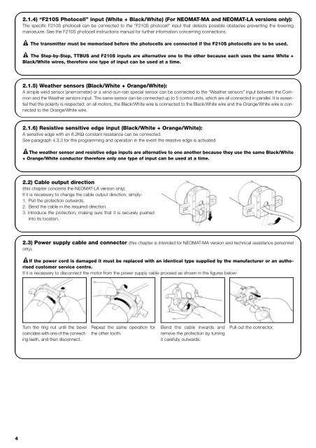
2.1.4) “F210S Photocell” input (White + Black/White) (For NEOMAT-MA and NEOMAT-LA versions only):The specific F210S photocell can be connected to the “F210S photocell” input that detects possible obstacles preventing the loweringmanoeuvre. See the F210S photocell instructions manual for further information concerning connections.The transmitter must be memorised before the photocells are connected if the F210S photocells are to be used.The Step-by-Step, TTBUS and F210S inputs are alternative one to the other because each uses the same White +Black/White wires, therefore one type of input can be used at a time.2.1.5) Weather sensors (Black/White + Orange/White):A simple wind sensor (anemometer) or a wind-sun-rain special sensor can be connected to the “Weather sensors” input between the Commonand the Weather sensors input. The same sensor can be connected up to 5 control units, which are all connected in parallel. It is essentialthat the polarity is respected: on all motors, the Black/White wire is connected to the Black/White wire and the Orange/White wire is connectedto the Orange/White wire.2.1.6) Resistive sensitive edge input (Black/White + Orange/White):A sensitive edge with an 8.2KΩ constant resistance can be connected.See paragraph 4.3.3 for the programming and operation in the event the resistive edge is activatedThe weather sensor and resistive edge inputs are alternative to one another because they use the same Black/White+ Orange/White conductor therefore only one type of input can be used at a time.2.2) Cable output direction(this chapter concerns the NEOMAT-LA version only).If it is necessary to change the cable output direction, simply:1. Pull the protection outwards.2. Bend the cable in the required direction.3. Introduce the protection, making sure that it is securely pushedinto its location.2.3) Power supply cable and connector (this chapter is intended for NEOMAT-MA version and technical assistance personnelonly).If the power cord is damaged it must be replaced with an identical type supplied by the manufacturer or an authorisedcustomer <strong>service</strong> centre.If it is necessary to disconnect the motor from the power supply cable proceed as shown in the figures below:Turn the ring nut until the bevelcoincides with one of the connectingteeth, and then disconnect.Repeat the same operation forthe other tooth.Bend the cable inwards andremove the protection by turningit carefully outwards.Pull out the connector.4