6.1 <strong>Joints</strong> toriques OR pour étanchéité radiale statique, cotes métriques ID 17,86 – 37,1 mm CS L R L R ID d 1 D d D 1 Logement extérieur Logement intérieur <strong>SKF</strong> recommande la fabrication de paliers de joints toriques conformes à la norme ISO 3601. Ce tableau indique les dimensions de joint torique pour des dimensions de paliers courantes Dimensions Logement extérieur Logement intérieur Codification Désignation ID CS L R D d 1 d D 1 +0,2 max. H9 h11 f8 H11 mm – – 17,86 2,62 3,6 0,8 23,02 18,83 18,20 22,39 – OR 17.86x2.62-N70 18,1 1,6 2,3 0,5 21 18,8 – – – OR 18.1x1.6-N70 18,64 3,53 4,8 1 25,43 19,71 19,00 24,72 210 OR 18.64x3.53-N70 18,72 2,62 3,6 0,8 23,81 19,62 19,00 23,19 116 OR 18.72x2.62-N70 18,77 1,78 2,4 0,5 22,23 19,61 19,05 21,67 018 OR 18.77x1.78-N70 19,1 1,6 2,3 0,5 22 19,8 – – – OR 19.1x1.6-N70 19,2 3 4 1 25 20,2 20,00 25 – OR 19.2x3.0-N70 20,22 3,53 4,8 1 27 21,28 20,55 26,27 211 OR 20.22x3.53-N70 20,35 1,78 2,4 0,5 23,8 21,18 20,63 23,25 019 OR 20.35x1.78-N70 20,63 2,62 3,6 0,8 25,8 21,61 21,03 25,22 – OR 20.63x2.62-N70 21,82 3,53 4,8 1 28,6 22,88 22,15 27,87 212 OR 21.82x3.53-N70 21,95 1,78 2,4 0,5 25,4 22,78 22,23 24,85 020 OR 21.95x1.78-N70 22,1 1,6 2,3 0,5 25 22,8 – – – OR 22.1x1.6-N70 22,2 3 4 1 28 23,2 23,00 28 – OR 22.2x3.0-N70 22,22 2,62 3,6 0,8 27,38 23,19 22,62 26,81 – OR 22.22x2.62-N70 23,4 3,53 4,8 1 30,18 24,46 23,72 29,44 213 OR 23.4x3.53-N70 23,47 2,62 3,6 0,8 28,58 24,39 23,80 27,99 119 OR 23.47x2.62-N70 23,52 1,78 2,4 0,5 26,98 24,36 23,81 26,42 021 OR 23.52x1.78-N70 23,81 2,62 3,6 0,8 28,97 24,78 24,21 28,4 – OR 23.81x2.62-N70 24,2 3 4 1 30 25,2 25,00 30 – OR 24.2x3.0-N70 24,99 3,53 4,8 1 31,78 26,06 25,32 31,04 214 OR 24.99x3.53-N70 302
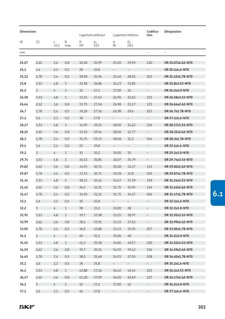
Dimensions Logement extérieur Logement intérieur Codification Désignation ID CS L R D d 1 d D 1 +0,2 max. H9 h11 f8 H11 mm – – 25,07 2,62 3,6 0,8 30,18 25,99 25,40 29,59 120 OR 25.07x2.62-N70 25,1 1,6 2,3 0,5 28 25,8 – – – OR 25.1x1.6-N70 25,12 1,78 2,4 0,5 28,58 25,96 25,40 28,02 022 OR 25.12x1.78-N70 25,8 3,53 4,8 1 32,58 26,86 26,13 31,85 – OR 25.8x3.53-N70 26,2 3 4 1 32 27,2 27,00 32 – OR 26.2x3.0-N70 26,58 3,53 4,8 1 33,35 27,63 26,90 32,62 215 OR 26.58x3.53-N70 26,64 2,62 3,6 0,8 31,75 27,56 26,98 31,17 121 OR 26.64x2.62-N70 26,7 1,78 2,4 0,5 30,18 27,56 26,98 29,6 023 OR 26.7x1.78-N70 27,1 1,6 2,3 0,5 30 27,8 – – – OR 27.1x1.6-N70 28,17 3,53 4,8 1 34,95 29,23 28,50 34,22 216 OR 28.17x3.53-N70 28,25 2,62 3,6 0,8 33,33 29,14 28,58 32,77 – OR 28.25x2.62-N70 28,3 1,78 2,4 0,5 31,75 29,13 28,58 31,2 024 OR 28.3x1.78-N70 29,1 1,6 2,3 0,5 32 29,8 – – – OR 29.1x1.6-N70 29,2 3 4 1 35 30,2 30,00 35 – OR 29.2x3.0-N70 29,74 3,53 4,8 1 36,53 30,81 30,07 35,79 – OR 29.74x3.53-N70 29,82 2,62 3,6 0,8 34,93 30,74 30,18 34,37 123 OR 29.82x2.62-N70 29,87 1,78 2,4 0,5 33,33 30,71 30,18 32,8 025 OR 29.87x1.78-N70 31,34 3,53 4,8 1 38,13 32,41 31,67 37,39 218 OR 31.34x3.53-N70 31,42 2,62 3,6 0,8 36,5 32,31 31,75 35,94 124 OR 31.42x2.62-N70 31,47 1,78 2,4 0,5 34,93 32,31 31,75 34,37 026 OR 31.47x1.78-N70 32,1 1,6 2,3 0,5 35 32,8 – – – OR 32.1x1.6-N70 6.1 32,2 3 4 1 38 33,2 33,00 38 – OR 32.2x3.0-N70 32,92 3,53 4,8 1 39,7 33,98 33,25 38,97 – OR 32.92x3.53-N70 32,99 2,62 3,6 0,8 38,1 33,91 33,33 37,52 – OR 32.99x2.62-N70 33,05 1,78 2,4 0,5 36,5 33,88 33,33 35,95 027 OR 33.05x1.78-N70 34,2 3 4 1 40 35,2 35,00 40 – OR 34.2x3.0-N70 34,52 3,53 4,8 1 41,3 35,58 34,85 40,57 220 OR 34.52x3.53-N70 34,59 2,62 3,6 0,8 39,7 35,51 34,93 39,12 126 OR 34.59x2.62-N70 34,65 1,78 2,4 0,5 38,1 35,48 34,93 37,55 028 OR 34.65x1.78-N70 35,1 1,6 2,3 0,5 38 35,8 – – – OR 35.1x1.6-N70 36,1 3,53 4,8 1 42,88 37,16 36,42 42,14 221 OR 36.1x3.53-N70 36,17 2,62 3,6 0,8 41,28 37,09 36,50 40,69 127 OR 36.17x2.62-N70 36,2 3 4 1 42 37,2 37,00 42 – OR 36.2x3.0-N70 37,1 1,6 2,3 0,5 40 37,8 – – – OR 37.1x1.6-N70 303
- Page 1 and 2:
Joints hydrauliques
- Page 3 and 4:
Joints hydrauliques SKF - informati
- Page 5 and 6:
3 Joints de tige et joints tampons
- Page 7 and 8:
Avant-propos Ce catalogue répertor
- Page 9 and 10:
Codage couleur pour les matériaux
- Page 11 and 12:
Répondre aux défis technologiques
- Page 13 and 14:
Roulements et ensembles-roulements
- Page 15 and 16:
Vérins hydrauliques Un vérin hydr
- Page 17 and 18:
Fonctions du joint de tige • il a
- Page 19 and 20:
Système SKF SEALJET Le système de
- Page 21:
19
- Page 24 and 25:
Informations techniques générales
- Page 26 and 27:
Informations techniques générales
- Page 28 and 29:
Informations techniques générales
- Page 30 and 31:
Informations techniques générales
- Page 32 and 33:
Informations techniques générales
- Page 34 and 35:
Informations techniques générales
- Page 36 and 37:
Informations techniques générales
- Page 38 and 39:
Informations techniques générales
- Page 40 and 41:
Informations techniques générales
- Page 42 and 43:
Informations techniques générales
- Page 44 and 45:
Informations techniques générales
- Page 47 and 48:
Joints de piston 2 Vue d’ensemble
- Page 49 and 50:
Vue d’ensemble des profils Profil
- Page 51 and 52:
Principes de base Déviation du pis
- Page 53 and 54:
Profil DPV Le profil DPV († fig.
- Page 55 and 56:
Joints de piston avec bagues anti-e
- Page 57 and 58:
Joints de piston et bagues de guida
- Page 59 and 60:
Joints de piston simple effet préc
- Page 61 and 62:
2.1 Joints de piston de profil MPV,
- Page 63 and 64:
2.2 Joints de piston de profil MPV,
- Page 65 and 66:
2.3 Joints de piston de profil LPV,
- Page 67 and 68:
2.4 Joints de piston de profil CPV,
- Page 69 and 70:
2.5 Joints de piston de profil GH,
- Page 71 and 72:
Dimensions Désignation D d L S R C
- Page 73 and 74:
Dimensions Désignation D d L S R C
- Page 75 and 76:
Dimensions Désignation D d L S R C
- Page 77 and 78:
Dimensions Désignation D d L S R C
- Page 79 and 80:
2.6 Joints de piston de profil APR,
- Page 81 and 82:
2.6 Joints de piston de profil APR,
- Page 83 and 84:
81 2.6
- Page 85 and 86:
2.7 Joints de piston de profil LCP,
- Page 87 and 88:
2.7 Joints de piston de profil LCP,
- Page 89 and 90:
2.8 Joints de piston de profil LTP,
- Page 91 and 92:
Dimensions Désignation D d L S R C
- Page 93 and 94:
2.9 Joints de piston de profil CUT,
- Page 95 and 96:
93 2.1 2.9
- Page 97 and 98:
2.10 Joints de piston de profil SCP
- Page 99 and 100:
97 2.10
- Page 101 and 102:
2.11 Joints de piston de profil MD-
- Page 103 and 104:
Dimensions Désignation D d L 1 L 2
- Page 105 and 106:
2.12 Joints de piston de profil UNP
- Page 107 and 108:
2.12 Joints de piston de profil UNP
- Page 109 and 110:
107 2.12
- Page 111:
Autres joints de piston Fig. 20 Exe
- Page 114 and 115:
Joints de tige et joints tampons Vu
- Page 116 and 117:
Joints de tige et joints tampons Pr
- Page 118 and 119:
Joints de tige et joints tampons Jo
- Page 120 and 121:
Joints de tige et joints tampons Pr
- Page 122 and 123:
Joints de tige et joints tampons Jo
- Page 124 and 125:
3.1 Profil S1S Données du profil S
- Page 126 and 127:
3.1 Joints de tige de profil S1S, c
- Page 128 and 129:
3.2 Profil ZBR Données du profil Z
- Page 130 and 131:
3.2 Joints de tige de profil ZBR, c
- Page 132 and 133:
3.2 Joints de tige de profil ZBR, c
- Page 134 and 135:
3.2 Joints de tige de profil ZBR, c
- Page 136 and 137:
3.3 Profil SIL Données du profil S
- Page 138 and 139:
3.3 Joints de tige de profil SIL, c
- Page 140 and 141:
3.4 Profil PTB Données du profil P
- Page 142 and 143:
3.4 Joints de tige de profil PTB, c
- Page 144 and 145:
3.4 Joints de tige de profil PTB, c
- Page 146 and 147:
3.4 Joints de tige de profil PTB, c
- Page 148 and 149:
3.4 Joints de tige de profil PTB, c
- Page 150 and 151:
3.4 Joints de tige de profil PTB, c
- Page 152 and 153:
3.4 Joints de tige de profil PTB, c
- Page 154 and 155:
3.4 Joints de tige de profil PTB, c
- Page 156 and 157:
3.4 Joints de tige de profil PTB, c
- Page 158 and 159:
3.4 Joints de tige de profil PTB, c
- Page 160 and 161:
3.4 Joints de tige de profil PTB, c
- Page 162 and 163:
3.4 Joints de tige de profil PTB, c
- Page 164 and 165:
3.4 Joints de tige de profil PTB, c
- Page 166 and 167:
3.5 Profil STD Données du profil S
- Page 168 and 169:
3.5 Joints de tige de profil STD, c
- Page 170 and 171:
3.5 Joints de tige de profil STD, c
- Page 172 and 173:
3.5 Joints de tige de profil STD, c
- Page 174 and 175:
3.5 Joints de tige de profil STD, c
- Page 176 and 177:
3.5 Joints de tige de profil STD, c
- Page 178 and 179:
3.5 Joints de tige de profil STD, c
- Page 180 and 181:
3.6 Profil DZ Données du profil DZ
- Page 182 and 183:
3.6 Joints de tige de profil DZ, co
- Page 184 and 185:
3.6 Joints de tige de profil DZ, co
- Page 186 and 187:
3.7 Profil DZR Données du profil D
- Page 188 and 189:
3.7 Joints de tige de profil DZR, c
- Page 190 and 191:
3.8 Profil RBB Données du profil R
- Page 192 and 193:
3.8 Joints tampons de profil RBB, c
- Page 194 and 195:
3.9 Profil S9B Données du profil S
- Page 196 and 197:
3.9 Joints tampons de profil S9B, c
- Page 198 and 199:
3.9 Joints tampons de profil S9B, c
- Page 200 and 201:
3.10 Profil RSB Données du profil
- Page 202 and 203:
3.10 Joints tampons de profil RSB,
- Page 204 and 205:
Joints de tige et joints tampons Au
- Page 206 and 207:
Joints de tige et joints tampons Pr
- Page 209 and 210:
Joints racleurs Vue d’ensemble de
- Page 211 and 212:
Vue d’ensemble des profils 4 209
- Page 213 and 214:
Fig. 2 Joints racleurs insérables
- Page 215 and 216:
Joints racleurs encliquetables Fig.
- Page 217 and 218:
Profil HW Le profil HW († fig. 11
- Page 219 and 220:
4.1 Joints racleurs de profil PA, c
- Page 221 and 222:
219 4.1
- Page 223 and 224:
4.2 Joints racleurs de profil MCW,
- Page 225 and 226:
4.2 Joints racleurs de profil MCW,
- Page 227 and 228:
Dimensions Désignation d 1) D L S
- Page 229 and 230:
4.3 Joints racleurs de profil PAD e
- Page 231 and 232:
4.4 Joints racleurs de profil DTW,
- Page 233 and 234:
Dimensions Désignation d 1) D L D
- Page 235 and 236:
Dimensions Désignation d 1) D L D
- Page 237 and 238:
235 4.4
- Page 239 and 240:
4.5 Joints racleurs de profil DX, c
- Page 241 and 242:
239 4.5
- Page 243 and 244:
4.6 Joints racleurs de profil HW, c
- Page 245 and 246:
4.6 Joints racleurs de profil HW, c
- Page 247 and 248:
245 4.6
- Page 249:
Autres joints racleurs Fig. 14 Exem
- Page 252 and 253:
Bagues de guidage et bandes de guid
- Page 254 and 255: Bagues de guidage et bandes de guid
- Page 256 and 257: Bagues de guidage et bandes de guid
- Page 258 and 259: 5.1 Bagues de guidage de tige ou pi
- Page 260 and 261: 5.1 Bagues de guidage de tige ou pi
- Page 262 and 263: 5.1 Bagues de guidage de tige ou pi
- Page 264 and 265: 5.2 Bagues de guidage de tige ou pi
- Page 266 and 267: 5.2 Bagues de guidage de tige ou pi
- Page 268 and 269: 5.2 Bagues de guidage de tige ou pi
- Page 270 and 271: 5.2 Bagues de guidage de tige ou pi
- Page 272 and 273: 5.2 Bagues de guidage de tige ou pi
- Page 274 and 275: 5.2 Bagues de guidage de tige ou pi
- Page 276 and 277: 5.2 Bagues de guidage de tige ou pi
- Page 278 and 279: 5.3 Bagues de guidage de tige RGR,
- Page 280 and 281: 5.3 Bagues de guidage de tige RGR,
- Page 282 and 283: 5.4 Bagues de guidage de piston PGR
- Page 284 and 285: 5.4 Bagues de guidage de piston PGR
- Page 286 and 287: Bagues de guidage et bandes de guid
- Page 288 and 289: Bagues de guidage et bandes de guid
- Page 290 and 291: Bagues de guidage et bandes de guid
- Page 293 and 294: Joints toriques et bagues anti-extr
- Page 295 and 296: Principes de base Tableau 1 Systèm
- Page 297 and 298: Normes de surface SKF fournit des j
- Page 299 and 300: Types de logements et dimensions Ty
- Page 301 and 302: par rapport à la pression de fonct
- Page 303: Dimensions Logement extérieur Loge
- Page 307 and 308: Dimensions Logement extérieur Loge
- Page 309 and 310: Dimensions Logement extérieur Loge
- Page 311 and 312: Dimensions Logement extérieur Loge
- Page 313 and 314: Dimensions Logement extérieur Loge
- Page 315 and 316: Dimensions Logement extérieur Loge
- Page 317 and 318: Dimensions Logement extérieur Loge
- Page 319 and 320: Codification Dimensions Logement ex
- Page 321 and 322: Codification Dimensions Logement ex
- Page 323 and 324: Codification Dimensions Logement ex
- Page 325 and 326: Codification Dimensions Logement ex
- Page 327 and 328: Dimensions Désignation ID CS w L 1
- Page 329 and 330: Dimensions Désignation ID CS w L 1
- Page 331 and 332: Codification Dimensions Désignatio
- Page 333 and 334: Codification Dimensions Désignatio
- Page 335 and 336: Codification Dimensions Désignatio
- Page 337 and 338: Codification Dimensions Désignatio
- Page 339 and 340: 337 6.4
- Page 341 and 342: Codification Dimensions Désignatio
- Page 343 and 344: Codification Dimensions Désignatio
- Page 345 and 346: Codification Dimensions Désignatio
- Page 347: Joints toriques encapsulés en PTFE
- Page 350 and 351: Autres applications de transmission
- Page 352 and 353: Autres applications de transmission
- Page 354 and 355:
Index des produits Profil/désignat
- Page 356:
skf.com