Cover CB124.qxp - Chamberlain
Cover CB124.qxp - Chamberlain
Cover CB124.qxp - Chamberlain

Create successful ePaper yourself
Turn your PDF publications into a flip-book with our unique Google optimized e-Paper software.
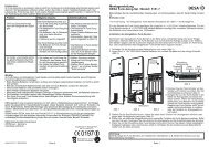
TECHNICAL DATA<br />
Voltage:<br />
230V~ ±10% 50Hz<br />
Transformer:<br />
230V/24V, 150VA<br />
Output Motor:<br />
24V/DC<br />
Consumption max.: max. 400W (in operation)<br />
Consumption Standby: max. 4 Watt (without accessories)<br />
Supply accessories: 24VDc / 600mA max.<br />
Operating temperature: -25ºC ÷ 55ºC<br />
Modes:<br />
Standard, Automatic<br />
Measurements:<br />
250x75mm (without box)<br />
Measurements Box: ca. 300mm x 220mm x 120mm<br />
Protection class Box: IP45<br />
Fuse:<br />
2 x 2A<br />
Remote control:<br />
max. 180 x Rolling Code<br />
feasible frequencies: 433MHz, 868MHz<br />
en-2<br />
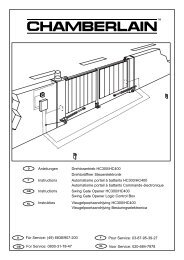
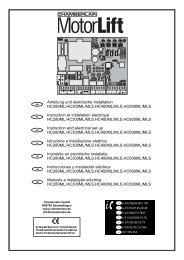
TYPICAL CONFIGURATION OF A UNIT:<br />
1. Motor (LYN/SCS)<br />
2. Control board<br />
3. Photocell (active for closing), max. height 200 mm<br />
First photocell.<br />
4. Photocell (active for opening and closing), max. height 200 mm<br />
Second photocell (optional).<br />
5. Flashing light (optional)<br />
Important visual information on the movement of the gate.<br />
6. Key-operated switch or wireless keypad (optional)<br />
Is mounted on the outside. The gate is opened by key or by<br />
entering a number.<br />
7. Contact strip (optional)<br />
Safeguards the gate on being touched. Contact strips can be<br />
mounted on the gate or on the pillars. If required, contact strips<br />
must be mounted at a height of up to 2.5m.<br />
+<br />
4<br />
CONTROL BOX<br />
The control consists of several components.<br />
- exterior installation box 1<br />
- cover for box 1<br />
- control 1<br />
- transformer 1<br />
- baseplate (pre-assembled) 1<br />
- cable bushing large 1<br />
- cable bushing small 3<br />
- fastening clips 6<br />
- screws 3,5 x 9,5 mm 4<br />
- large washer 1<br />
- screw large 1<br />
- spring lock washer 1<br />
- cable lug 1<br />
- nut M8 2<br />
- washer M8 1<br />
- large closure screws 5<br />
- small bag containing jumpers 1<br />
PREPARATION<br />
Open the 4 pre-cut holes at the bottom of the casing<br />
with a screwdriver or a similar device. Attach large<br />
cable bushing on the left then the rest as shown in<br />
picture. Humidity and water destroy the control. All<br />
openings and cable bushings must be sealed<br />
against water (waterproof). The control box with the<br />
motor control is to be mounted with the cable<br />
bushings facing down.