Cover CB124.qxp - Chamberlain
Cover CB124.qxp - Chamberlain
Cover CB124.qxp - Chamberlain

Create successful ePaper yourself
Turn your PDF publications into a flip-book with our unique Google optimized e-Paper software.
+<br />
+<br />
+<br />
+<br />
+<br />
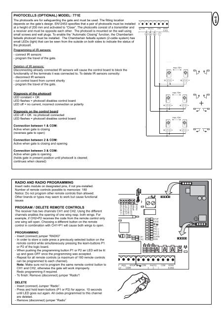
PHOTOCELLS (OPTIONAL) MODEL: 771E<br />
The photocells are for safeguarding the gate and must be used. The fitting location<br />
depends on the gate’s design. EN12453 specifies that a pair of photocells must be installed<br />
at a height of 200 mm and activated to “Close”. The photocells consist of a transmitter and<br />
a receiver and must be opposite each other. The photocell is mounted on the wall using<br />
small screws and wall plugs. To enable the “Automatic Closing” function, the <strong>Chamberlain</strong><br />
failsafe photocell must be installed. The <strong>Chamberlain</strong> failsafe system (2-cable system) has<br />
small LEDs (light) that can be seen from the outside on both sides to indicate the status of<br />
the photocell.<br />
Programming of IR sensors:<br />
- connect IR sensors<br />
- program the travel of the gate.<br />
COM<br />
PHOTO<br />
3 2 1<br />
+<br />
+<br />
+<br />
COM<br />
EDGE<br />
8.2KΩ<br />
en-8<br />
8.2 Ω<br />
Deletion of IR sensors:<br />
Disconnecting already connected IR sensors will cause the control board to block the<br />
functionality of the terminals it was connected to. To delete IR sensors correctly:<br />
- disconnect IR sensors<br />
- cut control board from current shortly<br />
- program the travel of the gate.<br />
+<br />
Diagnosis of the photocell<br />
LED constant = OK<br />
LED flashes = photocell disables control board<br />
LED off = no current, incorrect connection or polarity<br />
+<br />
Diagnosis on the control board<br />
LED off = OK no photocell connected<br />
LED flashes = photocell disables control board<br />
Connection between 1 & COM:<br />
Active when gate is closing<br />
(reverses gate to open)<br />
Connection between 2 & COM:<br />
Active when gate is closing and opening<br />
Connection between 3 & COM:<br />
Active when gate is opening<br />
(holds gate in present position until photocell is cleared;<br />
continues when cleared)<br />
RADIO AND RADIO PROGRAMMING<br />
Insert radio module on designated pins, if not pre-installed.<br />
Number of remote controls possible to memorize: 180<br />
Notice: Do not program other remote controls than allowed.<br />
Other brands or types may seem to work but cause functional<br />
issues<br />
PROGRAM / DELETE REMOTE CONTROLS<br />
The receiver has two channels CH1 and CH2. Using the different<br />
channels enables the opening of one wing resp. both wings. For<br />
example, if CH2=P2 receives the code from the remote control only<br />
one wing will open. Choosing a different button on the remote<br />
control in combination with CH1=P1 will cause both wings to open.<br />
PROGRAMMING<br />
- Insert (connect) jumper “RADIO”<br />
- In order to store a code press a previously selected button on the<br />
remote control while simultaneously pressing the learn-buttons P1<br />
or P2 of the logic board.<br />
- When pushing the programming button P1 or P2 an LED will be lit<br />
up and goes OFF once the programming was accepted.<br />
- Repeat for all remote controls (a maximum of 180 remote controls<br />
can be programmed to each channel).<br />
Note: Make sure not to program the same remote control button to<br />
CH1 and CH2, otherwise the gate will work improperly.<br />
Redo programming if required.<br />
- To finish: Remove (disconnect) jumper “Radio”!<br />
DELETE<br />
- Insert (connect) Jumper “Radio”.<br />
- Press and hold learn-buttons (P1 or P2) for approx. 10 seconds<br />
until LED goes out again. All codes programmed to this channel<br />
are deleted.<br />
- Remove (disconnect) jumper “Radio”<br />
1/2 MOTOR<br />
OPEN/STEP<br />
LIGHT/SPY<br />
OBSTACLE<br />
LOOP/EDGE<br />
SPEED<br />
RADIO<br />
T PED STOP<br />
ACT COM<br />
CH1<br />
CH2<br />
COM<br />
STOP<br />
EDGE<br />
PED<br />
PHO 1<br />
PHO 2<br />
PHO 3<br />
LEARN<br />
DGN<br />
PHOTO<br />
3 2 1<br />
COM<br />
EDGE<br />
8.2KΩ