catalogo vlm 2013 new
catalogo vlm 2013 new
catalogo vlm 2013 new

You also want an ePaper? Increase the reach of your titles
YUMPU automatically turns print PDFs into web optimized ePapers that Google loves.
DIMMERABILE<br />
since 1945<br />
DMXPWM RGB<br />
DMX<br />
DIMMABLE<br />
19<br />
115<br />
26<br />
34<br />
107<br />
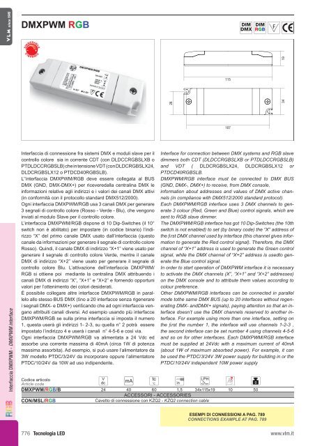
Interfaccia DMXPWM - DMXPWM interface<br />
Interfaccia di connessione fra sistemi DMX e moduli slave per il<br />
controllo colore sia in corrente CDT (con DLDCCRGBSLXB o<br />
PTDLDCCRGBSLB) che in tensione VDT (con DLDCRGBSLX24,<br />
DLDCRGBSLX12 o PTDCD40RGBSLB).<br />
L’’interfaccia DMXPWM/RGB deve essere collegata al BUS<br />
DMX (GND, DMX-DMX+) per riceveredalla centralina DMX le<br />
informazioni relative agli indirizzi e i valori dei canali DMX attivi<br />
(in conformità con il protocollo standard DMX512/2000).<br />
Ogni interfaccia DMXPWM/RGB usa 3 canali DMX per generare<br />
3 segnali di controllo colore (Rosso - Verde - Blu), che vengono<br />
inviati al modulo Slave per il controllo colore.<br />
L’interfaccia DMXPWM/RGB dispone di 10 Dip-Switches (il 10°<br />
switch non è abilitato) per impostare (in codice binario) l’indirizzo<br />
“X” del primo canale DMX usato dall’interfaccia (questo<br />
canale da informazioni per generare il segnale di controllo colore<br />
Rosso). Quindi, il canale DMX di indirizzo “X+1” viene usato per<br />
generare il segnale di controllo colore Verde, mentre il canale<br />
DMX di indirizzo “X+2” viene usato per generare il segnale di<br />
controllo colore Blu. L’attivazione dell’interfaccia DMXPWM/<br />
RGB si ottiene poi mediante la centralina DMX attribuendo i<br />
canali DMX di indirizzi “X”, “X+1” e “X+2” e fornendo opportuni<br />
valori per l’ottenimento dei colori desiderati.<br />
É possibile collegare altre interfacce DMXPWM/RGB in parallelo<br />
allo stesso BUS DMX (fino a 20 interfacce senza rigenerare<br />
i segnali DMX- e DMX+) verificando che ad ogni interfaccia vengano<br />
attribuiti canali diversi. Ad esempio usando più interfacce<br />
DMXPWM/RGB se sulla prima interfaccia si imposta il numero<br />
1, questa userà gli indirizzi 1- 2-3, su quella n° 2 potrà essere<br />
impostato l’indirizzo 4 e userà i canali n° 4-5-6 e così via.<br />
Ogni interfaccia DMXPWM/RGB va alimentata a 24 Vdc ed<br />
assorbe una corrente massima di 40mA (circa 1W di potenza<br />
massima assorbita). Ad esempio, si può usare l’alimentatore da<br />
3W modello PTDC/3/24V da incorporare oppure l’alimentatore<br />
PTDC/10/24V da 10W ad uso indipendente.<br />
Interface for connection between DMX systems and RGB slave<br />
dimmers both CDT (DLDCCRGBSLXB or PTDLDCCRGBSLB)<br />
and VDT ( DLDCRGBSLX24, DLDCRGBSLX12 or<br />
PTDCD40RGBSLB.<br />
DMXPWM/RGB interface must be connected to DMX BUS<br />
(GND, DMX-, DMX+) to receive, from DMX console,<br />
information about addresses and values of DMX active channels<br />
(in compliance with DMX512/2000 standard protocol).<br />
Each DMXPWM/RGB interface uses 3 DMX channels to generate<br />
3 colour (Red, Green and Blue) control signals, which are<br />
sent to RGB slave dimmer.<br />
The DMXPWM/RGB interface has got 10 Dip-Switches (the 10th<br />
switch is not enabled) to set (by binary code) the “X” address of<br />
the first DMX channel used by interface (this channel gives information<br />
to generate the Red control signal). Therefore, the DMX<br />
channel of “X+1” address is used to generate the Green control<br />
signal, while the DMX channel of “X+2” address is usedto generate<br />
the Blue control signal.<br />
In order to start operation of DMXPWM interface it is necessary<br />
to activate the DMX channels (X”, “X+1” and “X+2” addresses)<br />
on the DMX console and to attribute them values according to<br />
colour preference.<br />
Other DMXPWM/RGB interfaces can be connected in parallel<br />
mode tothe same DMX BUS (up to 20 interfaces without regenerating<br />
DMX- andDMX+ signals), paying attention so that an interface<br />
doesn’t use the DMX channels reserved to another interface.<br />
For example using more than one interface, setting on<br />
the first the number 1, the interface will use channels 1-2-3 ,<br />
the second interface can be set number 4 using channels 4-5-6<br />
and so on for other interfaces. Each DMXPWM/RGB interface<br />
must be supplied at 24Vdc with a maximum current of 40mA<br />
(about 1W of maximum absorbed power). For example, it can<br />
be used the PTDC/3/24V 3W power supply for building in or the<br />
PTDC/10/24V independent 10W power supply<br />
Codice articolo<br />
Article code<br />
DMXPWM/RGB/B 24 40 60 1,5 34x115x19 10 50<br />
ACCESSORI - ACCESSORIES<br />
CON/MSL/RGB<br />
Cavetto di connessione con KZQ2 - KZQ2 connection cable<br />
ESEMPI DI CONNESSIONI A PAG. 789<br />
CONNECTIONS EXAMPLE AT PAG. 789<br />
776<br />
Tecnologia LED<br />
www.<strong>vlm</strong>.it