F7000 - F7001
F7000 - F7001
F7000 - F7001

Create successful ePaper yourself
Turn your PDF publications into a flip-book with our unique Google optimized e-Paper software.
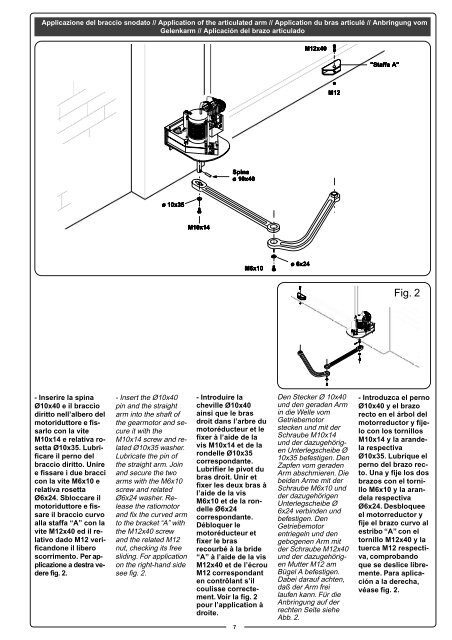
Applicazione del braccio snodato // Application of the articulated arm // Application du bras articulé // Anbringung vom<br />
Gelenkarm // Aplicación del brazo articulado<br />
M12x40<br />
"Staffa A"<br />
M12<br />
Spina<br />
ø 10x40<br />
ø 10x35<br />
M10x14<br />
M6x10<br />
ø 6x24<br />
Fig. 2<br />
- Inserire la spina<br />
Ø10x40 e il braccio<br />
diritto nell’albero del<br />
motoriduttore e fissarlo<br />
con la vite<br />
M10x14 e relativa rosetta<br />
Ø10x35. Lubrificare<br />
il perno del<br />
braccio diritto. Unire<br />
e fissare i due bracci<br />
con la vite M6x10 e<br />
relativa rosetta<br />
Ø6x24. Sbloccare il<br />
motoriduttore e fissare<br />
il braccio curvo<br />
alla staffa “A” con la<br />
vite M12x40 ed il relativo<br />
dado M12 verificandone<br />
il libero<br />
scorrimento. Per applicazione<br />
a destra vedere<br />
fig. 2.<br />
- Insert the Ø10x40<br />
pin and the straight<br />
arm into the shaft of<br />
the gearmotor and secure<br />
it with the<br />
M10x14 screw and related<br />
Ø10x35 washer.<br />
Lubricate the pin of<br />
the straight arm. Join<br />
and secure the two<br />
arms with the M6x10<br />
screw and related<br />
Ø6x24 washer. Release<br />
the ratiomotor<br />
and fix the curved arm<br />
to the bracket “A” with<br />
the M12x40 screw<br />
and the related M12<br />
nut, checking its free<br />
sliding. For application<br />
on the right-hand side<br />
see fig. 2.<br />
- Introduire la<br />
cheville Ø10x40<br />
ainsi que le bras<br />
droit dans l’arbre du<br />
motoréducteur et le<br />
fixer à l’aide de la<br />
vis M10x14 et de la<br />
rondelle Ø10x35<br />
correspondante.<br />
Lubrifier le pivot du<br />
bras droit. Unir et<br />
fixer les deux bras à<br />
l’aide de la vis<br />
M6x10 et de la rondelle<br />
Ø6x24<br />
correspondante.<br />
Débloquer le<br />
motoréducteur et<br />
fixer le bras<br />
recourbé à la bride<br />
“A” à l’aide de la vis<br />
M12x40 et de l’écrou<br />
M12 correspondant<br />
en contrôlant s’il<br />
coulisse correctement.<br />
Voir la fig. 2<br />
pour l’application à<br />
droite.<br />
7<br />
Den Stecker Ø 10x40<br />
und den geraden Arm<br />
in die Welle vom<br />
Getriebemotor<br />
stecken und mit der<br />
Schraube M10x14<br />
und der dazugehörigen<br />
Unterlegscheibe Ø<br />
10x35 befestigen. Den<br />
Zapfen vom geraden<br />
Arm abschmieren. Die<br />
beiden Arme mit der<br />
Schraube M6x10 und<br />
der dazugehörigen<br />
Unterlegscheibe Ø<br />
6x24 verbinden und<br />
befestigen. Den<br />
Getriebemotor<br />
entriegeln und den<br />
gebogenen Arm mit<br />
der Schraube M12x40<br />
und der dazugehörigen<br />
Mutter M12 am<br />
Bügel A befestigen.<br />
Dabei darauf achten,<br />
daß der Arm frei<br />
laufen kann. Für die<br />
Anbringung auf der<br />
rechten Seite siehe<br />
Abb. 2.<br />
- Introduzca el perno<br />
Ø10x40 y el brazo<br />
recto en el árbol del<br />
motorreductor y fíjelo<br />
con los tornillos<br />
M10x14 y la arandela<br />
respectiva<br />
Ø10x35. Lubrique el<br />
perno del brazo recto.<br />
Una y fije los dos<br />
brazos con el tornillo<br />
M6x10 y la arandela<br />
respectiva<br />
Ø6x24. Desbloquee<br />
el motorreductor y<br />
fije el brazo curvo al<br />
estribo “A” con el<br />
tornillo M12x40 y la<br />
tuerca M12 respectiva,<br />
comprobando<br />
que se deslice libremente.<br />
Para aplicación<br />
a la derecha,<br />
véase fig. 2.