ACM 400 S
ACM 400 S
ACM 400 S
- No tags were found...

Create successful ePaper yourself
Turn your PDF publications into a flip-book with our unique Google optimized e-Paper software.
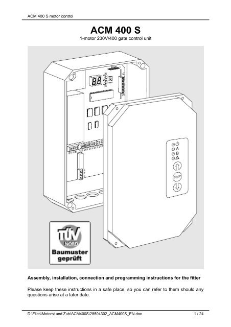
<strong>ACM</strong> <strong>400</strong> S motor control<strong>ACM</strong> <strong>400</strong> S1-motor 230V/<strong>400</strong> gate control unitAssembly, installation, connection and programming instructions for the fitterPlease keep these instructions in a safe place, so you can refer to them should anyquestions arise at a later date.D:\Files\Motorst und Zub\<strong>ACM</strong><strong>400</strong>S\28504302_<strong>ACM</strong><strong>400</strong>S_EN.doc 1 / 24
MIAMI 21AS ADOPTED – JANUARY 2011ARTICLE 9. LANDSCAPE REQUIREMENTSb. All other development:The landscape plan for development other than provided for in 9.4.2.1 above, shall beprepared by, and bear the seal of, a landscape architect licensed to practice in the Stateof Florida, or by persons authorized by Chapter 481, Florida Statutes, to preparelandscape plans or drawings. Preliminary landscape plans shall be provided as part ofthe submission for approval and shall:1. Be drawn to scale and include property boundaries, north arrow, graphic scale, anddate.2. Include a vegetation survey, including an aerial photograph which outlines thesubject site, provided at the same scale as the landscape plan.3. Delineate existing and proposed structures, parking spaces, driveways and othervehicular use areas, sidewalks, utilities, easements, height and voltage of powerlines on the property or adjacent property.4. Indicate the common and scientific name and quantity of plants to be installed usingthe "Landscape Legend" code format as prescribed by the Director of the PlanningDepartment.5. Identify all landscape features and non-living landscape materials.6. Show all areas of vegetation required to be preserved by law, including but notlimited to trees, specimen trees, native plant species, Natural Forest Communities,native habitats and wetlands.7. Illustrate geologic, historic and archeological features to be preserved.8. Depict stormwater retention/detention areas and areas excluded from maximumpermitted lawn area.9. Document Transect Zone, Net Lot area, maximum Lot coverage, required OpenSpace, and maximum permitted lawn area.10. Complete Preparer's Statement of Landscape Compliance form.c. Final landscape plans submitted for permit shall include all of the above, as well asthe following:1. A fully completed, permanently affixed "Landscape Legend" as prescribed by theDirector of the Planning Department.2. Critical layout dimensions for trees, plant beds and landscape features.IX.5
<strong>ACM</strong> <strong>400</strong> S motor control unita) Cables• The length of signal cables for sensors and control devices must not exceedmax 30m, in order to avoid EMC effects.• Avoid parallel layout of signal cables with power or antenna cables, to avoidcoupling interference.b) System (mains)[X17], [X18]• The control unit power supply unit must be protected on site with an all-pole shortcircuitproof motor protection switch with maximum permissible tripping range of2.5...4.0A! Dimension the supply lead according to the power input ...• for the drive unit (max. 2000W)• for the control unit ( approx 8VA)• and all external devices connected to it (e.g. sensors, control stations, lightingand signalling devices, etc.).[X18] Connect a 230V system to terminals "L1 / N / PE”.The terminals "L3" and "N" (terminals 7 and 8) must be jumpered![X17] Connect a <strong>400</strong>V system to terminals "L1...3 / N / PE".c) <strong>400</strong>V motor (3~)[X14]The load tap of the motor control unit and 3-phase operation is designed for a maxmotor output of 2000W / <strong>400</strong>V. However, a max operating time of 25% must not beexceeded.Connect the motor to terminals 12...15 [X14].The running direction switchover is determined by the motor terminals "V" and "U".d) 230V motor (1~)[X15]The load tap of the motor control unit and 1-phase mode is designed for max motoroutput of 1000W / 230V.Connect a 230V supply to terminals "L1 / N / PE" [X18].The terminals "L3" and "N" must be jumpered!Connect the motor to terminals 12...14 [X15], as shown in the diagram. The runningdirection switchover is determined by the motor terminals "V" and "U".e) Limit switch[X16]Limit switch operation is absolutely necessary to detect the respective end position.These can be e.g. roller or inductive limit switches, which are executed as breakcontactelements.Connect the limit switch to terminals 40...42 [X16].7 / 24
<strong>ACM</strong> <strong>400</strong> S motor control unitWarning!Do not connect the gate drive unit to the motor, until you are convinced the motorruns in the correct rotational direction – e.g. after electrical startup. Otherwisethere is a risk of accidents if the motor turns in an unexpected direction!Gates without a mechanical end stop must be secured via a second "safetylimit switch" downstream of the normal limit switch, if the gate causes a hazard ifthe end position is exceeded, e.g. due to a defective limit switch. The "safety limitswitch" must be connected to the "Emergency stop”, which then stops the gatemovement. slack cable switches or wicket safety devices must also be connected inthe "Emergency stop" safety circuit.f) Open/Closed/Stop input [X9]These control stations can be designed as pushbuttons, key-operated switches,coded locks or external radio buttons – and each as a make contact element.[X9.1] Connect the "Open" and "Closed" buttons to terminals 26...28.[X9.2] Connect the "Stop" button to terminals 29 / 30."Stop" is a purely function input without safety function!Gate status “Open” pressed “Closed” pressed “Stop” pressedstanding in limit position “Open“ - closes -standing in limit position “Closed“ opens - -standing in “Partly open” position opens closes -Stands somewhere along theopens closes -pathopens menu “D“ value: 00 Stop Stop Stop01 - Stop02 Stop closes03 - closescloses menu “D“ value: 00 Stop Stop Stop01 opens Stop02 Stop -03 opens -“Emergency stop“ is actuated - - -Automatic closing modeAs long as it ispressed the gateremainspermanently opencloses, keep opentime is ignoredStop, keep opentimerestartsThe "Open" and "Closed" functions can also be actuated via channels 2 / 3 of theoptional radio receiver, as described on page 13.g) Emergency stop [X19]This can be realised as a mushroom button or wicket safety device, etc., and is afloating break contact element.Connect the emergency stop button to terminals 38 / 39.If you do not want to connect an emergency stop button, these terminals must bejumpered!The "Emergency stop" function directly blocks the relay for the motor control. It is notpossible to start the motor via the dead-man’s mode or by other inputs, as long asterminals 38 / 39 are interrupted.8 / 24
<strong>ACM</strong> <strong>400</strong> S motor control unitGate statusReaction if “emergency stop” pressedAt a standstill, light is onLight goes out (specific light shut-down)opens / closesStopin limit position “open“ or “closed“ -Automatic closing mode Menu 9“ – value: 00Factory value: 01keep open time completely restartsAutomatic closing mode disabled up to thenext commandNote:This "emergency stop" function is merely a command function – it does not act as adisconnecting device according to DIN VDE 0100 Part 537. If necessary you mustimplement this facility on site!h) Membrane keyboard [X3.3], [X1], [X5]If you use the version with the membrane keyboard integrated in the cover [X1], [X5],connect it at the "Keyboard” slot on the printed circuit board [X3.3].When connecting, ensure that the ribbon cable is not twisted. The gate can also becontrolled from this, as via the separate buttons at terminals 26...30. Emergencyoperation (page Fehler! Textmarke nicht definiert.) is also possible via themembrane keyboard.i) Universal input [X8.1]With this you can realise both optional "partial opening mode" and "Automaticclosing"."Partial opening mode” enables only partial opening, e.g. as man lock. This isachieved by limiting the opening time.To do this connect a button (make contact element) to terminals 23 / 24 [X8.1].In "automatic closing mode”, automatic closing can be set via a time allowance.To do this, connect a switch, e.g. a time switch, to terminals 23 / 24 [X8.1].If menu "A" is set to 00, then automatic closing is only active when the switch isclosed!Menu Value Function“A” 00 Automatic closing mode01 Partial opening function: opening time…60 Limit of 01…60 sec.Menu Value Keep open time (automatic closing)“5” 00 Automatic closing off01…82In 2-second steps per digitFrom 2…164 seconds83…95In minute steps per digit from3…15min, with 5 s warning timeIf you have used a radio receiver (optional) (page 13), you can also use it to connectthe universal input (channel 4). This of course only makes sense if you have selectthe partial opening function in menu "A”.9 / 24
<strong>ACM</strong> <strong>400</strong> S motor control unitl) Power supply for sensors [X7]0.2 A max are available for the sensors power supply as• 24V~ at terminal 21• 12V= at terminal 22each applied against the 0V connection at terminal 20.m) Method of connection for "self-test"The receiver side of the photoelectric barrier or the 8K2 safety strips are testedduring self-test by short interruption of the 0V connections (earthing).You can also include the transmitter side in the self-test – by supply it with powervia the universal output (see page 13).n) Speed sensor [X7]• The speed sensor monitors running of the motor. If a sensor signal remains offalthough the motor has been started, the control unit stops the motor running withthe error message E2, as either the sensor is defective or a motor/transmissionbreak exists.• Obstruction / limit position detection via the speed sensors is not possible.• The type of speed sensor is set via menu “0”.[X7.1] Connect the signal output to terminals 19 / 20.Gate statusReactionStanding -running Menu “0“ – value: 00 no sensor connected -01 Type "Castalia" connected02 Type "DSLTA-51" connected03 Type "FACT" connectedIf signal cannot be measured 0.5safter motor starts: “Stop“ until nextcommand inputo) Photoelectric barrier [X7]You can connect photoelectric barriers, DWG strips, ground loops, etc. as floatingbreak contact elements to monitor the space within which the gate moves.[X7.2] Connect a photoelectric barrier to terminals 30 / 31.If you do not want to connect any photoelectric barrier, the terminals must bejumpered or disabled.p) Closing edge safety device [X7]4 safety strips can be connect to the control unit as closing edge safety devices, e.g.Type "8K2" or "-OSE".[X7.3] Connect the safety strips 1...4 to terminals 32...37.If using "8K2" strips, the outer surround of the safety strip must be connected toterminal 33 and/or 36 (0V).Any unused inputs must be jumpered with 8.2 kohl or disabled.OSE connection: +12V terminal 22 (brown cable),0V terminal 20 (white cable)Signal terminal 32, 34, 35, 37 (green cable)11 / 24
<strong>ACM</strong> <strong>400</strong> S motor control unitFunctionPhotoelectric LightbarrierMenu “8“Safety stripsMenu “1…4”8K2 OSESensor triggeringwhile openingSensor triggeringwhole closinggate at a standstill - - - No effect No effectDisable sensor 00 00 16 No effect No effectStop01 01 17 No effect Stop04 04 20 Stop No effect05 05 21 Stop StopRelease *)02 02 18 No effect Release *)08 08 24 Release *) No effect10 10 26 Release *) Release *)Reversing03 03 19 No effect opens12 12 28 closes No effect16 -- -- No effect opens17 -- No effect opens18 -- No effect opens-- -- -- No effect opensAutomatic closing afterquitting LS16 -- -- No effect Closes 0.5s aftercommand17 -- -- No effect Closes 3s aftercommand18 -- -- No effect Closes 7s aftercommandCombined functions06 06 22 Stop Release *)07 07 23 Stop opens09 09 25 Release *) Stop11 11 27 Release *) opens13 13 29 closes Stop14 14 30 closes Release *)15 15 31 closes opens*) Release = if an obstruction is detected the gate moves a short distance in the opposite direction (released)Release time(in 0.25s steps)Menu “B“ value 00….150.25s4.00sq) Light outputs [X10]Two lamps for signal and lighting purposes can be connected for 230V AC, namely...[X10.1] at terminals 9 / 10 with a load of max. 200 W,[X10.2] at terminals 10 / 11 with a load of max. 200 W.Gate status Menu “7”value Light output terminals 9 / 1000 No lightGate started 01…60Lit time from 0 600sin10s stepsin limit position “Closed“ 61 Light offin limit position “Open“Light onStopped along the pathLight flashes slowly (0.5Hz)opens / closedLight flashes quickly (4Hz)When motor starts 62 Short pulse (1.5s)Gate status Menu “6“ - value Warning light output terminals 10 / 11opens / closes00 Only while motor running01 4s before motor starts + while motorrunning02 10s before motor starts + while motorrunningCloses03 4s before motor starts + while motorrunning04 10s before motor starts + while motorrunning12 / 24
<strong>ACM</strong> <strong>400</strong> S motor control unitr) Universal output [X12]This universal output consists of a floating changeover contact, which can bestarted with different functions, for example...• for the self-test of the transmitter side of photoelectric barriers: During the selftest(page 17) the changeover contact briefly picks up and can therefore interrupta power supply passed via the break contact element (terminals 16 / 18) –which must be recognised as a command at the photoelectric barrier input aftermax 0.5s.• for connecting a traffic signal light: To do this, connect the “red” signal light tothe break content element and “green” to the make contact element. Thechangeover contact does not pick up until the limit position "Open", along thegate’s path and in the "Closed" limit position the signal light remains "red".• for special functions to be switched on by radio button, e.g. bell, time switch orpulse for garage gates. The changeover contact picks up if a radio signal iscorrectly received on channel 4.Menu “F” value Universal output terminals 16…1800 Self-test function01 Traffic light function02 Radio button (channel 4)s) Radio receiver (optional) [X4]If an optional radio receiver is installed, as described in the radio receiverinstructions, the following functions are available:Channel Function1 “Pulse“ (page 10f)2 “Open“ (see table)3 “Closed“ (see table)4 Partial opening function (page 11), or Universal output (menu “F” = 02)Radio commandcauses“Open“ (channel 2)“Closed“ (channel 3)Menu “C” value While opening While closing00 Stop Stop01 - closes02 Stop Stop03 - closes00 Stop Stop01 Stop Stop02 opens -03 opens -13 / 24
<strong>ACM</strong> <strong>400</strong> S motor control unit7) Putting into Service [X2]If the control unit has been installed and connected as described, it can now be putinto service:• First, check whether all non-connected inputs are closed, as far as necessary,e.g. at the inputs for ...• Emergency stop (page Fehler! Textmarke nicht definiert.)• Photoelectric barrier (page Fehler! Textmarke nicht definiert.)• Closing edge safety device (page Fehler! Textmarke nicht definiert.)• Ensure safety, regarding the remaining part of the whole system, in particular ...• ensure that when the motor is started up nobody can be injured and thesystem cannot be damaged.It makes sense, when switching the gate on for the first time, for the gate to be in themiddle of the gate path, to allow sufficient reaction time if unexpected movementsoccur.If you now switch on the system voltage, a complete self-test (see page 17) is nowcarried out.[X2.1] The display first displays "88" and then "CH" as an indication that the selftestis running.a) The LEDs on the printed circuit boardsignal the switched condition of the respective inputs / outputs:[X6.1] At terminals 23...39, lit LEDs mean that the respective inputs have beentriggered or are not closed off.[X6.2] At terminals 40...42, lit LEDs mean that the respective limit switch hastriggered, i.e. the gate is in this limit position.[X2.5] The lit LEDs under the display mean that the outputs for light and warninglight conduct voltage at terminals 9...11.[X2.1] The left-hand display point lights up if a signal from the speed sensor isreceived at terminals 19...20.[X2.1] The right-hand display point lights up, if automatic closing is activated.b) The LEDs on the membrane keyboard [X5]signal the gate status and indicate error statuses:[X5.1] The "Running" LED lights up...• continuously during normal operation• flashes if errors occur according to the "error messages" table.[X5.2] The LED "A" (gate) lights up...• continuously, if the gate is in the limit position "Open",• does not (= off), if the gate is in the limit position "Closed",• flashes slowly (0.5Hz), if the gate is stopped along the gate’s path,• flashes quickly (4 Hz), if the gate is moving open or closed.[X5.3] The LED "B" (radio) lights up if a valid radio command has been analysed.[X5.4] The LED "S" lights up if an error has been detected (e.g. a sensor triggered orEmergency Stop or undervoltage).14 / 24
c) Displayed errors [X2.1], [X5.4]Possible cause RemedyCode inthedisplay[X2.1]LED "S"flashes[X5.4]E1 1x control unit:Watchdog testnegativeE2 2x Speed sensor:No signaldetected 0.5safter motor startE3 3x photoelectricbarrier:Self-test negativeE4 4x safety strips: SelftestnegativeE55xMotor control: thegate has not leftthe limit switchwithin 2s ofstarting<strong>ACM</strong> <strong>400</strong> S motor control unitSwitch off voltage, wait 10sec, switch voltage back on.If error message remains, a hardware error exists in the control unit.The control unit must be replaced.Renewed motor start. If the error message remains:a) check connectionsb) check sensor type (menu “0“)c) switch off sensor (menu “0“ set to 00)d) Replace sensor/control unitSwitch off voltage, wait 10sec, switch voltage back on.If error message remains:a) Check setting menu “8“ and “F“ (external LS test) with respect toconnected photoelectric barrier.b) Check connection of the photoelectric barrier (power supply andsignal output)c) if a) and b) correct, there is possibly a hardware error in the controlunit. The control unit must be replaced.Switch off voltage, wait 10sec, switch voltage back on.If error message remains:a) Check setting menu “1“...“4“ with respect to connected safety strip.b) Check connection of the safety strip (resistance/function)c) if a) and b) correct, there is possibly a hardware error in the controlunit. The control unit must be replaced.Restart motor. If error remains.Gate won’t move: Check mechanics (motor, transmission, emergencyunlocking, gate frozen)Gate moves: Check limit switch, contact, wiring.or speed signal inidle mode.E6 6x control unit: ROMtestnegativeE7 7x control unit: RAMtestnegativeE8 8x control unit:EEPROM testnegativeE9 9x The gate wasmoved from thelimit position“Closed“ in idlemodeLP -- undervoltage,possible overloadUnauthorised speed signal at terminal 19 and 20. Check sensorpossibly switch off (Menu “0“ set to 00) or replace.Switch off voltage, wait 10sec, switch voltage back on.If error message remains, there is a hardware error in the controller.The control unit must be replaced.Switch off voltage, wait 10sec, switch voltage back on.If error message remains, there is a hardware error in the controller.The control unit must be replaced.Switch off voltage, wait 10sec, switch voltage back on.If the error message remains, the stored value of the control unit isinvalid. The control unit must be reset (see page Fehler! Textmarkenicht definiert.)a) A break-in attempt exists.b) The emergency release has been actuated.c) Limit switch in the limit position no longer actuatedThe power supply voltage to the control unit is temporarily orcontinuously too low.a) Check mains connection. (measure 230V)b) Low voltage output overloaded (too many loads connected atterminals 20-22? Disconnect to check)c) External control stations not floatingIf the cause of the error has been removed, you can quit the error message byentering the next command (not by radio!).15 / 24
<strong>ACM</strong> <strong>400</strong> S motor control unit8) Programming [X2]This chapter describes how you can change the preset default values in the controlunit. Which values are available and what effect they have is described in chapter 5,next to the respective possible connections.a) Functions of the pushbuttons[X2.2] Key "" value + / Menu + / Test and pulse function Open-Stop-Closed-Stop-...[X2.4] Key "" value - / Menu -[X2.3] Key "Menu" menu management with 7 segment displayb) Start programming mode• For safety reasons the motor is locked in programming mode, as if Emergencystop has been actuated.• Keep the "Menu" key pressed for longer than 1s, ...• until in the left-hand display segment the digit for the Menu "0...L" appears.• If you do not press any key for longer than 15s or press the "Menu" key forlonger than 1s, the programming mode is switched off again.c) Select menu / change value• You can use the arrow keys "" to now select the menu "0...L".• If you now briefly press the "Menu" key, the value just set for this menu itemappears in the display.• You can now use the "" keys to change the value, as described on pages8...16.• The value is immediately adopted, as soon as you set it.d) ResetYou can reset the values to the factory default settings, by pressing both ""keys in “Function” mode (approx 5s) until the two points in the display stopflashing.e) Change blockYou can block the control panel on the printed circuit board so that the menu valuescan only be read, however, it is not possible to change the values.• To do this, go to Menu "L", as described under a) and b).• Then simultaneously press both "" keys and the "Emergency stop" button.• You can now use the "Menu" key to switch the value in Menu "L" between...• 00 = free, changes possible• 01 = blocked, page through menu onlyThis block feature is useful, e.g. during a phone diagnosis, in order to enable you toread off the menus and notify the person at the other end without accidentallychanging anything.f) Quit programming modeIf you do not press any key for longer than 15s or press the "Menu" key for longerthan 1s, programming mode is terminated. The values are already accepted, as soonas you set them.The factory default settings are given in the table from page 20.16 / 24
<strong>ACM</strong> <strong>400</strong> S motor control unit9) OperationThis chapter is intended for the fitter and further processing industry – however it isnot for issuing to the owner/operator of the gate system.The end product manufacturer is responsible for preparing instructions for the gatesystem suitable for issuing to the owner/operator.You can find information on this e.g. in the following standards and regulations:• ZH 1/494: Guidelines for power operated doors and gates• DIN EN 60335-2-95: Requirements for vertically moved garage gates inresidential facilities• EN 12445 + EN 12453: Safe use of power-operated gates• DIN EN 62079: InstructionsThere are also legal requirements for regular checking of the safety devices.You must point out to the owner/operator that if drive units are remotely controlled,they must always have direct eye contact with the moving gate in order to avoidaccidents.a) Self-testThe control unit constantly performs various self-tests. If an error occurs the controlunit is locked and an error message is displayed (see table on page 15).Faulty self-tests are automatically repeated after around 1 min. If an error thenoccurs again, the next self-test is carried out by an external command (e.g. Pulse,but not via radio).Self-tests are carried out...• immediately after the control unit is switched on,• around 1s after reaching the limit position "Closed",• after a motor has been running for 20 min,• around every 4 h in idle mode.If an error message occurs continuously please contact our service department.b) Normal operation [X2.1], [X5.1]After a successful self-test, the control unit is ready to use.This is indicated at the LEDs in the optional membrane keyboard [X5.1] if ...• the green LED "running" is lit,• the red LED "S" however, is not lit.Or by a transverse bar in the left-hand display segment [X2.1].Bar in left-hang display segmentAt topIn the middleAt bottommoves upwardsMoves downwardsGate statuslimit position "Open"gate at standstill along the pathlimit position "Closed"OpeningClosing17 / 24
<strong>ACM</strong> <strong>400</strong> S motor control unitYou can now operate the gate system, either...• via the external control station, as connected in chapter 6)• or via die membrane keyboard (optional) [X5.5]..[X5.7]In this case the gate moves...• open when you press [X5.5]• closed when you press the Key [X5.7].The "Stop" key [X5.6] on the membrane keyboard has the same function, as Stop asexternal control station.LED "A" on the front membrane [X5.2]Continuously onContinuously offFlashes slowly (0.5Hz)Flashes quickly (4Hz)Gate statuslimit position "Open"limit position "Closed"gate stopped along the pathOpening or closingBefore each motor start the warning light indicates the motor will be starting soon asan advance warning. Both the time and running direction for this can be set (Menu"6", page Fehler! Textmarke nicht definiert.).c) Emergency operationIn order to enable controlled movement of the gate when safety equipment (closingedge safety device, photoelectric barrier) is continuously actuated (e.g. in case of adefect in a safety device)• keep one of the external "Open" / "Closed" buttons pressed for longer than 15s,• until the warning light goes on.• When you release the button the named waiting times are reset and the gate’smovement is interrupted. Simply repeat these steps for another 2s movement.Note: It must be an external button or a membrane keyboard key.Emergency operation is not possible via radio!d) Read out trip counterThe "H" menu is a pure display menu – it shows the number of "Open" movements ofthe gate system to date.• Go to Menu "H", as described on page 16.• The position of the number to be displayed is shown in the left-hand displaysegment, the corresponding value of the position is displayed in the right-handdisplay segmentExample: The consecutive display of the numbers 00 14 25 33 48 52 6- 7- thereforemeans 045382-- movements, this is the number displayed one after the other in theright-hand display segment.18 / 24
<strong>ACM</strong> <strong>400</strong> S motor control unit10) DisposalThe control unit does not contain any materials for which known disposal regulationsexist at the time these instructions were written (November 2005). The control unitdoes not contain any built-in energy sources.11) Extensions/Add-Ons[X3]On the printed circuit board there are three slots for optional extensions/add-ons,which have already been partly covered in these instructions:[X3.1] For the "Open", "Closed", "Pulse" and "Partial opening" functions or theuniversal-output, a radio receiver can be installed in the "Radio" slot (see page 13)[X4]. This is described in greater detail in the installation instructions for the radioreceiver.[X3.2] At "Slot A" the optional available multi-functional card MMZ442-50 can beinserted with the following functions:• One way road (red/green traffic signal lights)• Display motor run via traffic signal lights• Limit position display (gate open or closed)• Diverse service functionsThe MMZ442-50 card works correctly from software version V1.2 for the motorcontrol unit.[X3.3] An optional membrane keyboard can be connected to the control unit (seepages Fehler! Textmarke nicht definiert., 14, 17). For space reasons, its use is notrecommended together with the plug-in card MMZ442-50.19 / 24
<strong>ACM</strong> <strong>400</strong> S motor control unit12) Menu TableMenu Possible range Function / values Basic value Setting0 00...03 Connection of a SPEED SENSOR00 No sensor connected01 speed sensor type “Casali” available02 speed sensor “DSLTA-51” available03 speed sensor type “FAAC“ available1 00...31 Function of the CLOSING EDGE SAFETY DEVICE SE1Strip Opening Closing00 8K2 No effect No effect (test purposes)01 8K2 No effect Stop02 8K2 No effect Release03 8K2 No effect Reversing04 8K2 Stop No effect05 8K2 Stop Stop06 8K2 Stop Release07 8K2 Stop Reversing08 8K2 Release No effect09 8K2 Release Stop10 8K2 Release Release11 8K2 Release Reversing12 8K2 Reversing No effect13 8K2 Reversing Stop14 8K2 Reversing Release15 8K2 Reversing Reversing16 OSE No effect No effect (test purposes)17 OSE No effect Stop18 OSE No effect Release19 OSE No effect Reversing20 OSE Stop No effect21 OSE Stop Stop22 OSE Stop Release23 OSE Stop Reversing24 OSE Release No effect25 OSE Release Stop26 OSE Release Release27 OSE Release Reversing28 OSE Reversing No effect29 OSE Reversing Stop30 OSE Reversing Release31 OSE Reversing Reversing2 00...31 Function of the CLOSING EDGE SAFETY DEVICE SE2Settings as Menu 13 00...31 Function of the CLOSING EDGE SAFETY DEVICE SE3Settings as Menu 14 00...31 Function of the CLOSING EDGE SAFETY DEVICE SE4Settings as Menu 15 00...95 AUTOMATIC CLOSING / KEEP OPEN TIME00 Switched off01...82 2...164s in 2s steps83 3min, 84 4min, 85 5min, 86 6min, ... , 95 15minAdditionally 5 seconds warning time each6 00...04 WARNING LIGHT function00 Only while motor running01 4s before motor starts Open + Closed, while motor running02 10s before motor starts Open + Closed, while motor running03 4s before motor starts Closed, while motor running04 10s before motor starts Closed, while motor running7 00...62 LIGHT function00...60 Lit time of 0...600s in 10s steps61 Light output has gate status display62 Short pulse when motor started00(without sensor)0606090900(Off)00(while motorrunning)18(3.0min)20 / 24
<strong>ACM</strong> <strong>400</strong> S motor control unit8 00...18 Function of the PHOTOELECTRIC BARRIEROpeningClosing00 No effect No effect (test purposes)01 No effect Stop02 No effect Release03 No effect Reversing04 Stop No effect05 Stop Stop06 Stop Release07 Stop Reversing08 Release No effect09 Release Stop10 Release Release11 Release Reversing12 Reversing No effect13 Reversing Stop14 Reversing Release15 Reversing Reversing16 No effect Reversing Closure 0.5s after LSwarning time 0,5s17 No effect Reversing Closure 3.0s after LSwarning time 1.5s18 No effect Reversing Closure 7.0s after LSwarning time 4.0s9 00 / 01 EMERGENCY STOP00 keep open time (automatic closing) starts again from beginning afterEmergency stop.01 After Emergency stop Automatic closing is blocked until next command.A 00...60 UNIVERSAL INPUT function:00 Time switch: Automatic closing only when closed contact01...60 Partial opening function with 1...60s partial opening timeB 00...15 RELEASE TIMERelease after photoelectric barriers or safety strips command00...15 0.25s...4,00s in 0.25s stepsC 00...03 RADIO OPEN / CLOSED while motor running00 FUNK-OPEN: Stop during opening, Stop while closing (panic function)RADIO CLOSED: Stop while opening, Stop while closing (panic function)01 RADIO OPEN: No effect while opening, Reversing while closingRADIO CLOSED: Stop while opening, Stop while closing (panic function)02 RADIO OPEN: Stop while opening, Stop while closing (panic function)RADIO CLOSED: Reversing while opening, no effect while closing03 RADIO OPEN: No effect while opening, Reversing while closingRADIO CLOSED: Reversing while opening, no effect while closingD 00...03 inputs OPEN / CLOSED while motor running00 OPEN: Stop while opening, Stop while closing (panic function)CLOSED: Stop while opening, Stop while closing (panic function)01 OPEN: No effect while opening, Reversing while closingCLOSED: Stop while opening, Stop while closing (panic function)02 OPEN: Stop while opening, Stop while closing (panic function)CLOSED: Reversing while opening, no effect while closing03 OPEN: No effect while opening, Reversing while closingCLOSED: Reversing while opening, no effect while closingE 00...03 PULSE / DEAD MAN’s mode with OPEN / CLOSED input00 OPEN: Pulse CLOSED: Pulse01 OPEN: Pulse CLOSED: dead man’s02 OPEN: dead man’s CLOSED: Pulse03 OPEN: dead man’s CLOSED: dead man’sF 00 / 01 UNIVERSAL OUTPUT 200 Photoelectric barrier test (interruption in transmitter voltage)01 Traffic signal lights (idle position in limit position “Open“, otherwise alwaysconnected)H Display only! READ OUT TRIPS COUNTERLeft position: “0“...“5“, right position corresponds to 100,000s... 1sL 00 / 01 SERVICE MODE00 Control panel unblocked, normal setting possibilities01 Control panel locked, no changes possible.Change from Menu “F“:Emergency stop, Key + and Key - actuated, Switch over with menu key!0501(Block AZ)05(5s partialopening)07(2.00s)00(Panic function)00(Panic function)00(Pulse)01(Traffic signallight)-00(unblocked/released)21 / 24
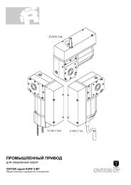
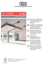
<strong>ACM</strong> <strong>400</strong> S motor control unit13) Figures/DiagramsX1X2X3X4X5X6X7 X8 X922 / 24
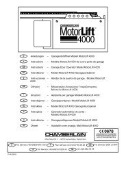
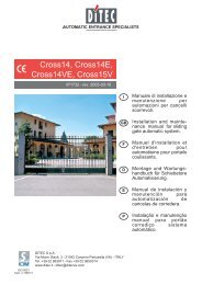
<strong>ACM</strong> <strong>400</strong> S motor control unitX10X11X12X13X14X15X16X17X18X1923 / 24
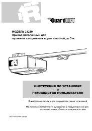
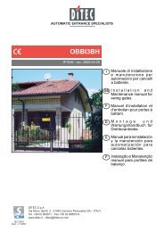
<strong>ACM</strong> <strong>400</strong> S motor control unit14) Block CIRCUIT DIAGRAM24 / 24