Anleitungen â Garagentorantriebe Modell 5580, 3780 Instructions ...
Anleitungen â Garagentorantriebe Modell 5580, 3780 Instructions ...
Anleitungen â Garagentorantriebe Modell 5580, 3780 Instructions ...

You also want an ePaper? Increase the reach of your titles
YUMPU automatically turns print PDFs into web optimized ePapers that Google loves.
CH<br />
A<br />
D<br />
<strong>Anleitungen</strong> – <strong>Garagentorantriebe</strong> <strong>Modell</strong> <strong>5580</strong>, <strong>3780</strong><br />
CH<br />
B<br />
F<br />
<strong>Instructions</strong><br />
– Modèle <strong>5580</strong>, <strong>3780</strong> de ouvre-porte de garage<br />
GB<br />
<strong>Instructions</strong> – Garage Door Operator Model <strong>5580</strong>, <strong>3780</strong><br />
DK<br />
Instruktioner<br />
– Model <strong>5580</strong>, <strong>3780</strong> Garageportsåbner<br />
E<br />
Instrucciones – Abridor de la puerta de garage,<br />
Modelo <strong>5580</strong>, <strong>3780</strong><br />
GR<br />
O‰ËÁ›Â˜<br />
– M˯·ÓÈÛÌfi˜ AÓÔ›ÁÌ·ÙÔ˜ °Î·Ú·˙fiappleÔÚÙ·˜,<br />
MÔÓÙ¤ÏÔ <strong>5580</strong>, <strong>3780</strong><br />
I<br />
Istruzioni – Apriporta per garage <strong>Modell</strong>o <strong>5580</strong>, <strong>3780</strong><br />
N<br />
Instruksjonene– Garasjeportåpner, <strong>Modell</strong> <strong>5580</strong>, <strong>3780</strong><br />
B<br />
NL<br />
Instrukties<br />
– Model <strong>5580</strong>, <strong>3780</strong> Garagedeuropener<br />
P<br />
Instruções<br />
– Operador automático de porta,<br />
Modelo <strong>5580</strong>, <strong>3780</strong><br />
S<br />
Instruktioner – Garageportöppnare <strong>Modell</strong> <strong>5580</strong>, <strong>3780</strong><br />
SF<br />
Ohjeet – Autotallin oven avaaja, Malli <strong>5580</strong>, <strong>3780</strong><br />
114A2788C<br />
i<br />
D<br />
F<br />
GB<br />
NL<br />
(+49) 06838-907-250<br />
(+33) 03.87.98.15.84<br />
(+44) 01935 848526<br />
(+31) 020.673.3626
Start by reading These Import Safety <strong>Instructions</strong><br />
Failure to comply with the following instructions may result in serious personal injury or property damage.<br />
• Read these instructions carefully<br />
• The garage door opener is designed and tested to offer reasonable safe service provided it is installed and<br />
operated in strict accordance with the instructions in this manual.<br />
These safety alert symbols mean Warning – a personal safety or property damage instruction. Read these<br />
instructions carefully.<br />
WARNING: If your garage has no service entrance door, Model 1702E Outside Quick Release must be installed. This accessory<br />
allows manual operation of the garage door from outside in case of power failure.<br />
Keep garage door balanced. Sticking or binding doors<br />
must be repaired. Garage doors, door springs, cables,<br />
pulleys, brackets and their hardware are under extreme<br />
tension and can cause serious personal injury. Do not<br />
attempt to loose, move or adjust them. Call for garage<br />
door service.<br />
Do not wear rings, watches or loose clothing while<br />
installing or servicing a garage door opener.<br />
To avoid serious personal injury from entanglement,<br />
remove all ropes connected to the garage door<br />
before installing the door opener.<br />
Installation and wiring must be in compliance with your<br />
local building and electrical codes. Connect the power<br />
supply cord only to properly earthed mains.<br />
Lightweight doors of fiberglass, aluminum or steel<br />
must be substantially reinforced to avoid door<br />
damage. (See page 3.) The best solution is to check<br />
with your garage door manufacturer for an opener<br />
installation reinforcement kit.<br />
The safety reverse system test is very important.<br />
Your garage door MUST reverse on contact with a<br />
40mm obstacle placed on the floor. Failure to properly<br />
adjust the opener may result in serious personal injury<br />
from a closing garage door. Repeat the test once a<br />
month and make any needed adjustments.<br />
This unit should not be installed in a damp or wet<br />
space.<br />
Door must not extend over public byway during<br />
operation.<br />
Contents Page Illustration<br />
Safety Rules . . . . . . . . . . . . . . . . . . . . . . . 1<br />
Before you Begin . . . . . . . . . . . . . . . . . . . 1<br />
Door Types . . . . . . . . . . . . . . . . . . . . . . . . 1 . . . . . . . . . . . . . . . . 1<br />
Tools Required . . . . . . . . . . . . . . . . . . . . . 2 . . . . . . . . . . . . . . . . 2<br />
Hardware Provided . . . . . . . . . . . . . . . . . 2 . . . . . . . . . . . . . . . . 3<br />
Completed Installation . . . . . . . . . . . . . . 2 . . . . . . . . . . . . . . . . 4<br />
Assembly . . . . . . . . . . . . . . . . . . . . . . . . . . 2 . . . . . . . . . . . . . 5-11<br />
Installation . . . . . . . . . . . . . . . . . . . . . . . 2-4 . . . . . . . . . . . . 12-21<br />
Programming your Opener & Remote . . 4 . . . . . . . . . . . . . . . 22<br />
Program your Keyless Entry . . . . . . . . . .5 . . . . . . . . . . . . . . .23<br />
The force, as measured on the closing edge of the<br />
door, should not exceed 400 N (40kg). If the closing<br />
force is more than 400 N, the Protector System must<br />
be installed. Do not use the force setting procedure<br />
to compensate for a binding or sticking garage door.<br />
Excessive force will interfere with the proper operation of<br />
the Safety Reverse System or damage the garage door.<br />
Permanently fasten the caution label adjacent to the<br />
lighted door control button as a reminder of safe<br />
operating procedures.<br />
Disengage all existing garage door locks to avoid<br />
damage to garage door.<br />
Install the lighted door control button (or any additional<br />
push buttons) in a location where the garage door is<br />
visible, at a height of at least 1,5m and out of the<br />
reach of children. Do not allow children to operate<br />
push button(s) or remote control(s). Serious personal<br />
injury from a closing garage door may result from misuse<br />
of the opener.<br />
Activate opener only when the door is in full view,<br />
free of obstructions and opener is properly adjusted.<br />
No one should enter or leave the garage while the<br />
door is in motion. Do not allow children to play near<br />
the door.<br />
Use manual release only to disengage the trolley and, if<br />
possible, only when the door is closed. Do not use the<br />
red handle to pull the door open or closed.<br />
Disconnect electric power to the garage door opener<br />
before making repairs or removing covers.<br />
This product is provided with a power supply cord of<br />
special design which, if damaged, must be replaced by<br />
a power supply cord of the same type; such a power<br />
supply cord may be obtained from your local LiftMaster<br />
distributor and must be fitted by a specialist.<br />
Adjustment . . . . . . . . . . . . . . . . . . . . . . . . 5 . . . . . . . . . . . . 24-26<br />
Install the Protector System <br />
(Optional) . . . . . . . . . . . . . . . . . . . . . . . . . 5 . . . . . . . . . . . . 27<br />
Special Features of the<br />
<strong>5580</strong>/<strong>3780</strong> . . . . . . . . . . . . . . . . . . . . . . . . .6 . . . . . . . . . . . . 28<br />
Accessories . . . . . . . . . . . . . . . . . . . . . . . 6 . . . . . . . . . . . . 29<br />
Replacement Parts . . . . . . . . . . . . . . . . . . 6 . . . . . . . . . . 30-31<br />
Having a Problem . . . . . . . . . . . . . . . 6-7<br />
Care of your Opener . . . . . . . . . . . . . . . . 7<br />
Maintenance of your Operator . . . . . . . . 7<br />
Operation of your Opener . . . . . . . . . . . . 8<br />
Specifications . . . . . . . . . . . . . . . . . . . . . . 8<br />
Before You Begin<br />
1. Look at the wall or ceiling above the garage door. The header bracket must be securely fastened to structural supports.<br />
2. Do you have a finished ceiling in your garage If so, a support bracket and additional fastening hardware (not supplied) may be required.<br />
3. Depending on your door's construction, you might need a special door arm. See your dealer.<br />
4. Do you have an access door in addition to the garage door If not, Model 1702E Outside Quick Release Accessory is required.<br />
5. Determine the type of door and whether the Chamberlain Arm or Protector System is required.<br />
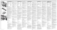
1 Door Types<br />
A. One-Piece Door with Horizontal Track Only<br />
B. One-Piece Door with Horizontal and Vertical Track – Special door arm (E, The Chamberlain Arm) and The Protector System (29 (9))<br />
are required. See your dealer.<br />
C. Sectional Door with Curved Track – See 20B – connect door arm. The Protector System (29 (9) is required for doors that are over 2.5m in<br />
height.<br />
D. Canopy door – Special door arm (E, The Chamberlain Arm) and The Protector System (29 (9)) are required. See your dealer.<br />
E. The Chamberlain Arm for use on door types B and D.<br />
1-GB
2<br />
3<br />
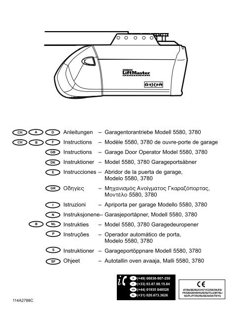
Hardware Provided<br />
(1) Clevis Pin (1)<br />
(2) Wood Screws (8)<br />
(3) Screws (2)<br />
(4) Clevis Pins (2)<br />
(5) Hex Screws (4)<br />
(6) Rope<br />
(7) Handle<br />
(8) Insulated Staples<br />
4<br />
Completed Installation<br />
(9) Anchors (2)<br />
(10) Lock Washer (7)<br />
(11) Nuts (7)<br />
(12) Ring Fastener (3)<br />
(13) 8mm Anchors (6)<br />
(14) Sheet Metal Screws (4)<br />
(15) Carriage Bolts (2)<br />
(16) Stop Bolt<br />
As you proceed with the assembly, installation and adjustment<br />
procedures in this manual, you may find it helpful to refer back to<br />
this illustration of a completed installation.<br />
(1) Header Sleeve<br />
(9) Light Lens<br />
(2) Chain Pulley Bracket<br />
(10) Manual Release<br />
(3) Trolley<br />
Rope & Handle<br />
(4) Rail<br />
(11) Curved Door Arm<br />
(5) Chain<br />
(12) Straight Door Arm<br />
(6) Hanging Bracket<br />
(13) Door Bracket & Plate<br />
(7) Power Cord<br />
(14) Header Bracket<br />
(8) Opener<br />
(15) Trolley Release Arm<br />
ASSEMBLY SECTION<br />
IMPORTANT: If you have a canopy or dual track one-piece door,<br />
you need to use the instructions packed with The Chamberlain<br />
Arm Accessory in conjunction with this Owner's Manual when<br />
assembling the rail.<br />
5 Assemble the Rail<br />
NOTE: If your opener came with a one piece rail, proceed to step 8.<br />
Grease inside edges of rail sections using grease (1). Place rail<br />
pieces (2) on flat surface for assembly. All four rail sections are<br />
interchangeable. Slide rail braces (3) onto rail section. Connect rail by<br />
sliding rail brace onto next rail section. Tap rail assembly (4) on piece<br />
of wood (5) until rail sections are flush. Repeat with remaining rail<br />
sections.<br />
Install the Chain<br />
6<br />
Remove chain from carton and lay chain out on floor (do not allow<br />
chain to twist). Push pins of master link bar (3) through chain link (4)<br />
and hole in back end of trolley (5). Push cap (2) over pins and onto<br />
notches. Slide clip-on spring (1) over cap and onto pin notches until<br />
both pins are securely locked in place.<br />
7 Insert Chain into Rail & Assemble Header<br />
Sleeve<br />
Slide pulley bracket (1) and inner trolley (2) into back (opener end) of<br />
rail assembly (3), be sure to insert pulley bracket as shown with arrow<br />
(4) pointing toward front (header end) of rail (5). Push bracket toward<br />
front (header end ) of rail (5). Insert carriage bolt (6) through header<br />
sleeve bracket (7). Loosely thread spring nut (8) onto carriage bolt.<br />
Insert carriage bolt (6) of header sleeve assembly (7) into bold cut out<br />
in pulley bracket (1). Slide header sleeve assembly (7) on to front<br />
(header end) of rail (4).<br />
Attach Trolley to Rail<br />
8<br />
Slide outer trolley (1) into rail assembly (2), be sure arrow on trolley<br />
(3) is heading in direction of door is heading in direction of door (4).<br />
Slide outer trolley down rail until it engages with inner trolley.<br />
Attach Chain Spreader<br />
9<br />
Tools Required<br />
Attach chain spreader (1) to opener (2) with phillips pan head<br />
screws (3).<br />
114A2788C-GB<br />
10 Fasten Rail to Opener & Install Chain<br />
Remove four washered bolts (1) from top of opener. Place rail (2) on<br />
opener, flush with stops (3) on top of opener. Wrap chain (4) around<br />
slot in spreader (5) and over sprocket (6). Push idler pulley bracket<br />
assembly toward front of the rail to eliminate excess slack in chain.<br />
Align bolt holes on brackets (7) with bolt holes on opener. Secure<br />
brackets to opener with previously removed bolts . Tighten bolts<br />
securely. The opener sprocket teeth must engage the chain.<br />
Insert bolt (8) into trolley stop bolt hole (9) secure with lock washer<br />
(10) and nut (11).<br />
CAUTION: Use only those bolts mounted in the top of opener.<br />
Use of any other bolts will cause serious damage to opener.<br />
Assemble Header Sleeve<br />
11<br />
Thread spring nut on carriage bolt unit finger tight. Insert a<br />
screwdriver tip (1) into one of the slots of the nut ring (2) and brace it<br />
firmly against the header sleeve. Place an open end wrench (3) on<br />
the square end of the spring nut (4), slightly rotate nut about 1/4 turn<br />
clockwise until nut ring (2) is released against header sleeve (5). This<br />
sets spring to optimum chain tension. chain may slip off sprocket if<br />
chain is too loose. If chain does slip re-tighten spring nut by turing nut<br />
clockwise 1/2 turn. Do NOT overtighten chain.<br />
INSTALLATION SECTION<br />
Wear protective goggles when working overhead to protect your<br />
eyes from injury.<br />
Disengage all existing garage door locks to avoid damage to the<br />
garage door.<br />
To avoid serious personal injury from entanglement, remove all<br />
ropes connected to the garage door before installing the opener.<br />
It is recommended that the opener be installed 2,1m (7 feet) or more<br />
above the floor where space permits.<br />
12 Position the Header Bracket<br />
The header bracket must be rigidly fastened to a structural<br />
support of the garage. Reinforce the wall or ceiling with a 40mm<br />
(1-1/2") board if necessary. Failure to comply may result in<br />
improper operation of safety reverse system.<br />
You can attach the header bracket either to the header wall (1) or to<br />
the ceiling (3). Follow the instructions which will work best for your<br />
particular requirements.<br />
With the door closed, mark the vertical centerline (2) of the garage<br />
door. Extend line onto header wall above the door.<br />
Open door to highest point of travel. Draw an intersecting horizontal<br />
line (4) on header wall 5cm (2") above high point to provide travel<br />
clearance for top edge of door.<br />
Install the Header Bracket<br />
13<br />
NOTE: Refer to vertical center and horizontal lines created in<br />
step 12 for proper placement or header bracket.<br />
A. Wall Mount: Center the bracket (1) on the vertical guideline (2)<br />
with the bottom edge of the bracket on the horizontal line (4)<br />
(with the arrow pointing toward the ceiling). Mark all of the bracket<br />
holes (5). Drill 4,5mm (3/16") pilot holes and fasten the bracket<br />
with wood screws (3). For concrete mount, use concrete anchors<br />
provided.<br />
B. Ceiling Mount: Extend vertical guideline (2) onto the ceiling.<br />
Center the bracket (1) on the vertical mark no more than 150mm<br />
(6") from the wall. Make sure the arrow is pointing toward the wall.<br />
Mark all of the bracket holes (5). Drill 4,5mm (3/16") pilot holes and<br />
fasten the bracket with wood screws (3). For concrete ceiling<br />
mount, use concrete anchors (6) provided.<br />
Attach Rail to Header Bracket<br />
14<br />
Position opener on garage floor below the header bracket. Use<br />
packing material to protect the cover. Raise rail until holes in the<br />
header sleeve and holes in the header bracket align. Join with clevis<br />
pin (1). Insert ring fastener (2) to secure.<br />
NOTE: To enable the rail to clear sectional door springs, it may be<br />
necessary to lift opener onto a temporary support. The opener must<br />
either be secured to a support or held firmly in place by another<br />
person.<br />
2-GB
15 Position the Opener<br />
NOTE: A 25mm (1") board (1) is convenient for setting an ideal doorto-rail<br />
distance (unless headroom is not sufficient).<br />
Raise the opener onto a stepladder. Open garage door. Place a<br />
25mm (1") board (1) laid flat on the top section of door near the<br />
centerline as shown. Rest the rail on the board.<br />
If the raised door hits the trolley, pull down on the trolley release arm<br />
to disconnect the inner and outer trolley sections. The trolley can<br />
remain disconnected until connecting door arm to trolley is<br />
completed.<br />
16 Hang the Opener<br />
The opener must be securely fastened to a structural support of<br />
the garage.<br />
Three representative installations are shown. Yours may be different.<br />
Hanging brackets (1) should be angled (Figure A) to provide rigid<br />
support. On finished ceilings, (Figure B) attach a sturdy metal bracket<br />
(not supplied) (4) to a structural support before installing the opener.<br />
For concrete ceiling mount, (Figure C), use concrete anchors (5)<br />
provided.<br />
On each side of opener measure the distance from the opener to the<br />
structural support (or ceiling).<br />
Cut both pieces of the hanging bracket to required lengths. Flatten<br />
one end of each bracket and bend or twist to fit the fastening angles.<br />
Do not bend at the bracket holes. Drill 4,5mm (3/16") pilot holes in<br />
the structural supports (or ceiling). Attach flattened ends of brackets<br />
to supports with wood screws (2).<br />
Lift opener and fasten to hanging brackets with screw, lock washer<br />
and nut (3). Check to make sure rail is centered over the door.<br />
Remove 25mm (1") board. Operate door manually. If door hits the<br />
rail, raise header bracket. Use rail grease and lubricate bottom<br />
surface of rail (6).<br />
17 Attach Emergency Release Rope &<br />
Handle<br />
Thread one end of rope (1) through hole in top of red handle so<br />
"NOTICE" reads right side up as shown (3). Secure with an overhand<br />
knot (2). Knot should be at least 25mm (1") from end of the rope to<br />
prevent slipping.<br />
Thread other end of rope through hole in release arm of the outer<br />
trolley (4). Adjust rope length so that handle is 1,8m (6 feet) above<br />
the floor. Secure with an overhand knot.<br />
NOTE: If it is necessary to cut rope, heat seal cut end with a match or<br />
lighter to prevent fraying.<br />
18 Install Light<br />
Press the release tabs on both sides of lens (2). Gently rotate lens<br />
back and downward until the lens hinge is in the fully open position.<br />
Do not remove the lens. Install a 40 watt (socket size E27), maximum<br />
light bulb (1) in the socket (3) as shown. The light will turn on and<br />
remain lit for 2-1/2 minutes when power is connected. After 2-1/2<br />
minutes it will turn off. Reverse the procedure to close the lens.<br />
Replace burned out bulbs with rough service light bulbs.<br />
19 Install Lighted Door Control Button<br />
Locate push buttons where the garage door is visible (at a<br />
height of at least of 1,5m), away from door and door hardware<br />
and out of the reach of children.<br />
Serious personal injury from a moving garage door may result<br />
from misuse of opener. Do not allow children to operate the<br />
lighted door control button or remote control transmitter.<br />
Permanently fasten the caution label on the wall near the lighted<br />
door control button as a reminder of safe operating procedures.<br />
There are 2 screw terminals (1) on the back of the lighted door<br />
control button (2). Strip about 6mm (1/4") of insulation from bell wire<br />
(4). Separate wires enough to connect the white/red wire to terminal<br />
screw 1 and the white wire to terminal screw 2.<br />
Fasten the lighted door control button to an inside garage wall with<br />
sheet metal screws (3) provided. Drill 4mm (5/32") holes and use<br />
anchors (6) if installing into drywall. A convenient place is beside the<br />
service door and out of reach of children.<br />
Run the bell wire up the wall and across the ceiling to the garage<br />
door opener. Use insulated staples (5) to secure wire. The receiver<br />
quick connect terminals are located on the back panel of the opener.<br />
Connect the bell wire to the terminals as follows: white/red to red (7)<br />
and white to white (8).<br />
Operation of the Lighted Door Control Button<br />
Press to open or close the door. Press again to reverse the door<br />
during the closing or opening cycle.<br />
20 Fasten Door Bracket<br />
If yours is a canopy or dual-track one-piece style garage door, a door<br />
arm conversion kit is required. Follow the installation instructions<br />
included with the replacement door arm. Exercise care in removing and<br />
assembling arm conversion kit. Keep fingers away from the sliding<br />
parts.<br />
NOTE: Horizontal and vertical reinforcement is needed for lightweight<br />
garage doors.<br />
Sectional and One-Piece Door Installation Procedure:<br />
Door bracket (1) has left and right side fastening holes. Assemble<br />
and install the bracket and plate (2) if your installation requires top<br />
and bottom fastening holes.<br />
1. Center bracket (with or without plate, as required) at the top of<br />
inside face of door as shown. Mark holes.<br />
2. A. Wooden doors<br />
Drill 8mm holes (5/16") and fasten the door bracket with nut,<br />
lock washer, and carriage bolt (3) or use wood screws.<br />
B. Sheet metal doors<br />
Fasten with sheet metal screws (4).<br />
C. One-piece door optional<br />
Fasten with sheet metal screws (4).<br />
3-GB<br />
Connect Electric Power<br />
TO AVOID INSTALLATION DIFFICULTIES, DO NOT RUN THE<br />
GARAGE DOOR OPENER UNTIL INSTRUCTED TO DO SO.<br />
Connect the opener to a mains which is properly EARTHED<br />
according to the wiring instruction tag attached to power supply<br />
cord (and as specified by local code).<br />
114A2788C-GB
21 Assemble Door Arm and Set Limits<br />
NOTE: For one-piece doors, do not connect door arm to trolley<br />
before adjusting limits. Failure to follow instructions may result in<br />
damage to door. See below.<br />
A. ONE-PIECE DOOR INSTALLATION:<br />
Connect straight door arm (1) and curved door arm sections (2) to<br />
obtain the longest possible length with hardware (3, 4 & 5). With door<br />
closed, connect straight door arm section to door bracket with a<br />
clevis pin (6). Secure with a ring fastener (7).<br />
Before connecting door arm to trolley, adjust travel limits. Limit<br />
adjustment screws are located on left side panel.<br />
Open Door Adjustment: Decrease up limit. Turn up limit adjustment<br />
screw counterclockwise 4-1/2 turns.<br />
Press door control button. Trolley will travel to full open position (8).<br />
Manually raise door to open position (parallel to floor) and lift door<br />
arm (9) to trolley. The arm should touch trolley just in back of door<br />
arm connector hole (10) as shown in solid line drawing. Increase up<br />
limit if necessary. One full turn equals 7,5cm (3") of door travel.<br />
Closed Door Adjustment: Decrease down limit. Turn down limit<br />
adjustment screw clockwise 4 complete turns.<br />
Press door control button. Trolley will travel to full closed position<br />
(11). Manually close door and lift door arm (12) to trolley. The arm<br />
should touch trolley just ahead of door arm connector hole (10) as<br />
shown in dotted line drawing. Decrease down limit if necessary. One<br />
full turn equals 7,5cm (3") of door travel.<br />
Connect Door Arm to Trolley: With door closed, connect curved arm<br />
to trolley with remaining clevis pin. Secure with ring fastener. NOTE:<br />
Lift door slightly to make connection if necessary.<br />
Run opener through a complete travel cycle. If door has a slight<br />
"backward" slant in full open position, decrease up limits until door<br />
is parallel to floor.<br />
B. SECTIONAL DOOR INSTALLATION:<br />
Connect according to Figure B, then proceed to Step 23.<br />
22 Program your Opener & Remote<br />
Activate the opener only when door is in full view, free of<br />
obstruction and properly adjusted. No one should enter or leave<br />
garage while door is in motion. Do not allow children to operate<br />
push button(s) or remote(s). Do not allow children to play near<br />
the door.<br />
Your garage door opener receiver and remote control transmitter are<br />
set to a matching code. If you purchase additional remote controls,<br />
the garage door opener must be programmed to accept the new<br />
remote code.<br />
Program the Receiver to Match Additional Remote Control<br />
Codes:<br />
Using the “LEARN” Button<br />
1. Press and release the “learn” button on the motor unit. The learn<br />
indicator light will glow steadily for 30 seconds (1).<br />
2. Within 30 seconds, press and hold the button on the hand-held<br />
remote that you wish to operate your garage door (2).<br />
3. Release the button when the motor unit light blinks. It has learned<br />
the code. If light bulb is not installed, two clicks will be heard (3).<br />
Using the Multi-Function Door Control (optional):<br />
1. Press and hold the button on the hand-held remote that you wish<br />
to operate your garage door (4).<br />
2. While holding the remote button, press and hold the LIGHT button<br />
on the Multi-Function Door Control (5).<br />
3. Continue holding both buttons while you press the push bar on the<br />
Multi-Function Door Control (all three buttons are held) (6).<br />
4. Release buttons when the motor unit light blinks. It has learned the<br />
code. If light bulb is not installed, two clicks will be heard (7).<br />
Now the opener will operate when the remote control push button is<br />
pressed. If you release the remote control push button before the<br />
opener lights flash, the opener has not learned the code.<br />
To Erase all Remote Control Codes<br />
To deactivate any unwanted remote, first erase all codes:<br />
Press and hold the “learn” button on motor unit until the learn<br />
indicator light goes out (approximately 6 seconds). All previous codes<br />
are now erased. Reprogram each remote or keyless entry you wish to<br />
use.<br />
3-Channel Remote:<br />
If provided with your garage door opener, the large button is factory<br />
programmed to operate it. Additional buttons on any rolling code<br />
3-channel remote or mini-remote can be programmed to operate<br />
other rolling code garage door openers or gates.<br />
4-GB<br />
114A2788C-GB
23 Program your Keyless Entry (optional)<br />
Activate the opener only when door is in full view, free of<br />
obstruction and properly adjusted. No one should enter or leave<br />
garage while door is in motion. Do not allow children to operate<br />
push button(s) or remote(s). Do not allow children to play near<br />
the door.<br />
NOTE: Your new Keyless Entry must be programmed to operate your<br />
garage door opener.<br />
Program the Receiver to Match Additional Remote Control Code<br />
Using the “LEARN” Button:<br />
1. Press and release the “learn” button (1) on opener. The learn<br />
indicator light will glow steadily for 30 seconds.<br />
2. Within 30 seconds, enter a four digit personal identification number<br />
(PIN) of your choice on the keypad (2), then press and hold the<br />
ENTER button.<br />
3. Release the button when the opener light blinks (3). It has learned<br />
the code. If light bulb is not installed, two clicks will be heard.<br />
NOTE: This method requires two people if the Keyless Entry is<br />
already mounted outside the garage.<br />
Using the Multi-Function Door Control (optional):<br />
1. Enter a four digit personal identification number (PIN) of your<br />
choice on the keypad, then press and hold ENTER (4).<br />
2. While holding the ENTER button, press and hold the LIGHT button<br />
on the Multi-Function Door Control (5).<br />
3. Continue holding the ENTER and LIGHT buttons while you press<br />
the push bar on the Multi-Function Door Control (all three buttons<br />
are held) (6).<br />
4. Release buttons when the opener light blinks. It has learned the<br />
code. If light bulb is not installed, two clicks will be heard (7).<br />
24 Limit Adjustment<br />
Run the opener through a complete travel cycle. Limit adjustments<br />
are not necessary when the door opens and closes completely and<br />
doesn't reverse unintentionally in the fully closed position.<br />
Locate the button (1) on the back panel of motor unit. Push the button<br />
twice to enter into Force Setting Mode.<br />
NOTE: Repeated operation of the opener during adjustment<br />
procedures may cause motor to overheat and shut off. Allow a 15<br />
minute cooling period after 5 continuous operations of the opener.<br />
Read the following carefully before proceeding to Force Adjustment.<br />
Use a screwdriver to make limit adjustments.<br />
If Door Doesn't Open Completely but Opens at Least 1,5m (5<br />
feet): Increase up travel. Turn the up limit adjustment screw (3)<br />
clockwise. One turn equals 5cm (2") of travel.<br />
If door does not open at least 1,5m (5 feet). Adjust force, see<br />
Force Adjustment: Place the opener into the Force Adjustment<br />
Mode, see Force Adjustment.<br />
If Door Doesn't Close Completely: If door arm is at maximum<br />
length, increase down travel. Turn down limit adjustment screw (2)<br />
counterclockwise. One turn equals 5cm (2") of travel. If the door still<br />
will not close completely, the header bracket is positioned too high.<br />
If Opener Reverses in Fully Closed Position: Decrease down<br />
travel. Turn down limit adjustment screw (2) clockwise. One turn<br />
equals 5cm (2") of travel.<br />
If Door Reverses when Closing and there is no Interference to<br />
Travel Cycle: Test door for binding. Pull manual release handle.<br />
Manually open and close door. If door is binding, call a door<br />
serviceman. If door is not binding or unbalanced, place the opener<br />
into the Force Setting Mode, see Force Settings.<br />
PROCEED TO STEP 25 “FORCE SETTINGS” TO COMPLETE<br />
STEP 24 “LIMIT ADJUSTMENT”. Forces must be learned in order<br />
for limit adjustments to operate properly.<br />
25 Force Settings<br />
The force, as measured on the closing edge of the door, should not<br />
exceed 400N (40kg). If the closing force is measured to more than<br />
400N, the Protector System must be installed See step 27.<br />
The force setting button is located on the back panel of the motor<br />
unit. The force setting regulates the amount of power required to<br />
open and close the door. If the forces are too light, door travel may be<br />
interrupted by nuisance reversals.<br />
Locate the button (1) on the back panel of motor unit. Push the button<br />
twice to enter into Force Setting Mode. The LED (Indicator Light) will<br />
flash. Push the wall control or the programmed remote control that<br />
was shipped with your opener. The door will travel to either the OPEN<br />
or CLOSE position. Push the button again, the door will travel to the<br />
opposite position. Push the button again if the LED is stilling blinking.<br />
The door must travel through a complete cycle UP and DOWN in<br />
order for the force to be set properly. If the unit reverses before it<br />
reaches the Open or Close Limit repeat the process. The LED<br />
(indicator light) will stop flashing when the force has been learned.<br />
Note: If unable to set limits return to section 24.<br />
26 Test the Safety Reverse System<br />
The safety reverse system test is important. Garage door must<br />
reverse on contact with a 40mm obstacle laid flat on the floor.<br />
Failure to properly adjust opener may result in serious personal<br />
injury from a closing garage door. Repeat test once a month and<br />
adjust as needed.<br />
Procedure: Place a 40mm obstacle (1) laid flat on the floor under the<br />
garage door. Operate the door in the down direction. The door must<br />
reverse on the obstruction. If the door stops on the obstruction, it is<br />
not traveling far enough in the down direction. Increase the down<br />
limit by turning down limit adjustment screw counterclockwise 1/4<br />
turn. Repeat test.<br />
When the door reverses on the 40mm obstacle, remove the<br />
obstruction and run the opener through a complete travel cycle. Door<br />
must not reverse in closed position. If it does, adjust Limits and<br />
Force and repeat safety reverse test.<br />
Test that the door will not fully open when a 20kg weight is added to<br />
the bottom of the door.<br />
27 Install the Protector System<br />
(See accessories)<br />
Install this accessory for all installations on Canopy doors,<br />
1 piece dual track doors, doors over 2.5m and when the closing<br />
force as measured on the bottom of the door is over 400N<br />
(40kg).<br />
After opener has been installed and adjusted, The Protector<br />
System accessory can be installed. <strong>Instructions</strong> are included with<br />
this accessory.<br />
The Protector System provides an additional measure of<br />
safety against a small child being caught under a garage door.<br />
It uses an invisible beam which, when broken by an obstruction,<br />
causes a closing door to open and prevents an open door from<br />
closing and is strongly recommended for homeowners with young<br />
children.<br />
Note: The opener will automatically detect the protector system when<br />
it is installed. The opener will not close unless the sensors are<br />
aligned.<br />
5-GB<br />
114A2788C-GB
28 Special Features<br />
A. Door within a door connection<br />
Disconnect opener from power!<br />
Remove cover. Locate auxiliary terminal block (TB1) on the<br />
control board. Remove jumper from terminal leads 1 and 2 (not<br />
shown). Replace with contact switch leads as shown.<br />
B. Flashing light connection<br />
The flashing light can be installed anywhere. Connect light leads<br />
to terminals 3 and 4 on the terminal block.<br />
C. Coaxial antenna adapter<br />
A coaxial antenna connection can be used if the transmitter<br />
range is too short. Cut off the existing antenna. Use standard<br />
coax cable and connector. Strip off end of insulation to “X”<br />
dimension.<br />
433 MHz: X = 250mm. Reposition antenna.<br />
Accessories<br />
29<br />
(1) Model 94330E Single-Function Remote Control<br />
(2) Model 4332E 2-Function Remote Control<br />
(3) Model 94333E 3-Function Remote Control<br />
(4) Model 94335E 3-Function Mini Remote Control<br />
(5) Model 9747E Keyless Entry System<br />
(6) Model 78LM Multi-Function Door Control Panel<br />
(7) Model 760E Outside Keylock<br />
(8) Model 1702E Outside Quick Release<br />
(9) Model 770E The Protector System<br />
(10) Model 1703E The Chamberlain Arm<br />
(11) Model FLA230 Flashing Light Kit<br />
(12) Model 16200LM Pedestrian Door Switch<br />
(13) Model MDL100LM Mechanical Door Latch Kit<br />
(14) Model EQL01 Door Handle Quick Release<br />
(15) Model 100027 1-Position Key Switch (Flush Mount -<br />
100010)<br />
Model 100041 2-Position Key Switch (Flush Mount -<br />
100034)<br />
WIRING INSTRUCTIONS FOR ACCESSORIES<br />
Keyless Entry System – To opener terminals: Red-1 and White-2<br />
Outside Keylock – To opener terminals: Red-1 and White-2<br />
Protector System – To opener terminals: White-2 and Black-3<br />
Door Control Panel – To opener terminals: Red-1 and White-2<br />
30 31 Replacement Parts<br />
HAVING A PROBLEM<br />
1. Opener doesn't operate from either door control or remote:<br />
• Does the opener have electric power Plug lamp into outlet. If it<br />
doesn't light, check the fuse box or the circuit breaker. (Some<br />
outlets are controlled by a wall switch.)<br />
• Have you disengaged all door locks Review installation instruction<br />
warnings on page 1.<br />
• Is there a build-up of ice or snow under door The door may be<br />
frozen to ground. Remove any obstruction.<br />
• The garage door spring may be broken. Have it replaced.<br />
• Repeated operation may have tripped the overload protector in the<br />
motor. Wait 15 minutes. Try again.<br />
2. Opener operates from remote but not from door control:<br />
• Is door control button lit If not, remove the bell wire from the<br />
opener terminals. Short the red and white terminals by touching<br />
both terminals at the same time with a piece of wire. If the opener<br />
runs, check for a faulty wire connection at the door control, a short<br />
under the staples, or a broken wire.<br />
• Are wiring connections correct Review page 3.<br />
3. Door operates from door control but not from remote:<br />
• Check battery. Replace battery if necessary.<br />
• Is the light at the wall control flashing Press button with key-symbol<br />
to unlock the opener against remote controls.<br />
• Is the receiver LED flashing at the back-side of the opener when the<br />
transmitter is pressed The opener receiver must re-learn the<br />
remote control code. Follow the instructions on page 4.<br />
• If you purchased a new remote control then check at carton of<br />
remote control for compatibility or call the Service Hotline.<br />
4. Remote has short range:<br />
• Is battery installed If needed, change the battery.<br />
• Change the location of the remote control on the car.<br />
• A metal garage door, foil-backed insulation or metal siding will<br />
reduce the transmission range.<br />
• Use outside coaxial antenna adapter to move antenna.<br />
5. Door reverses for no apparent reason and opener light doesn't<br />
blink:<br />
• Is something obstructing the door Pull manual release handle.<br />
Operate door manually. If it is unbalanced or binding, call for<br />
professional garage door service.<br />
• Clear any ice or snow from garage floor area where garage<br />
door closes.<br />
• Review Force Settings. Open and close the door in learn mode for<br />
several (3-5) consecutive cycles to allow the operator to adjust to<br />
inconsistent doors.<br />
• If door reverses in FULLY CLOSED position, re-learn travel limits.<br />
Repeat safety reverse test after adjustment is complete.<br />
The need for occasional adjustment of the force and limit settings is<br />
normal. Weather conditions in particular can affect door travel.<br />
6. Door reverses for no apparent reason and opener light blinks<br />
for 5 seconds after reversing:<br />
Check The Protector System (if you have installed this accessory).<br />
If the light is blinking, correct alignment.<br />
Note: Continuously holding down the door control button will allow<br />
the door to close if the protector system is not properly aligned. The<br />
transmitter will not close the door. The opener lights will blink.<br />
7. Opener noise is disturbing in living quarters of home:<br />
If operational noise is a problem because of proximity of the opener<br />
to the living quarters, Vibration Isolator Kit 41A3263 can be installed.<br />
This kit was designed to reduce the "sounding board effect" and is<br />
easy to install.<br />
8. The garage door opens and closes by itself:<br />
• Delete all remote controls and reprogram.<br />
• Make sure remote push button is not stuck "on".<br />
• Disconnect all push buttons or key switches attached and wait one<br />
day.<br />
6-GB<br />
114A2788C-GB
9. Door stops but doesn't close completely:<br />
Review Limit Adjustment section.<br />
Repeat safety reverse test after any adjustment of door arm length,<br />
close force or down limit.<br />
10. Door opens but won't close:<br />
• Check The Protector System (if you have installed this<br />
accessory). If the light is blinking, correct alignment.<br />
• If opener light does not blink and it is a new installation, check the<br />
down force.<br />
Repeat the safety reverse test after the adjustment is complete.<br />
11. Opener light does not turn on:<br />
Replace light bulb (40 Watts maximum). Replace burned out bulbs<br />
with rough service light bulbs.<br />
12. Opener light does not turn off:<br />
There may be a defective earth at the ceiling or wall receptacle.<br />
The unit must be earthed.<br />
13. Opener strains or reversed during opening:<br />
Door may be unbalanced or springs are broken. Close door and use<br />
manual release rope and handle to disconnect trolley. Open and<br />
close door manually. A properly balanced door will stay in any point<br />
of travel while being supported entirely by its springs. If it does not,<br />
call for professional garage door service to correct the problem. Do<br />
not change force settings.<br />
14. Opener motor hums briefly, then won't work:<br />
• Garage door springs are broken. SEE ABOVE.<br />
• If problem occurs on first operation of opener, door is locked.<br />
Disable door lock. If chain was removed and reinstalled, the motor<br />
may be out of phase. Remove chain; cycle motor to down position.<br />
Observe drive sprocket. When it turns in clockwise direction and<br />
stops in down position, re-install chain.<br />
Repeat safety reverse test after adjustment is complete.<br />
15. Opener won't activate due to power failure:<br />
• Pull manual release rope and handle down and back to disconnect<br />
trolley. Door can be opened and closed manually. When the power<br />
is restored, pull the manual release handle straight down. The next<br />
time the opener is activated, the trolley will reconnect.<br />
• The Outside Quick Release accessory (if fitted) disconnects the<br />
trolley from outside the garage in case of power failure.<br />
CARE OF YOUR OPENER<br />
When properly installed, opener will provide high performance with<br />
a minimum of maintenance. The opener does not require additional<br />
lubrication.<br />
Limit Adjustments: These adjustments must be checked and<br />
properly set when opener is installed. Only a screwdriver is<br />
required. Weather conditions may cause some minor changes in the<br />
door operation, requiring some re-adjustments, particularly during the<br />
first year of operation.<br />
Refer to the limit adjustments and force settings on page 5. Follow<br />
the instructions carefully and repeat the safety reverse test after<br />
any adjustment.<br />
Remote Control Transmitter: The portable remote control may be<br />
secured to a car sun visor with the clip provided. Additional remotes<br />
can be purchased at any time for use in all vehicles using garage.<br />
Refer to Accessories. Any new remotes must be set to the same<br />
code as the original remote.<br />
Remote Control Battery: The lithium batteries should produce<br />
power for up to 5 years. If transmission range lessens, check the<br />
battery.<br />
To Change Battery: To replace batteries, use the visor clip or<br />
screwdriver blade to pry open the case. Insert batteries positive side<br />
up. To replace cover, snap shut along both sides. Do not dispose of<br />
the old battery with household waste. Take batteries to a proper<br />
disposal center.<br />
MAINTENANCE OF YOUR OPENER<br />
Once a Month:<br />
• Repeat safety reverse test. Make any necessary adjustments.<br />
• Manually operate door. If it is unbalanced or binding, call for<br />
professional garage door service.<br />
• Check to be sure door opens and closes fully. Adjust Limits and/or<br />
Force settings if necessary.<br />
Once a Year:<br />
• Oil door rollers, bearings and hinges. The opener does not require<br />
additional lubrication. Do not grease the door tracks.<br />
• GREASE THE RAIL AND THE TROLLEY.<br />
7-GB<br />
114A2788C-GB
OPERATION OF YOUR OPENER<br />
Your opener can be activated by any of the following devices:<br />
• The Lighted Door Control Button. Hold the button down until door<br />
starts to move.<br />
• The Outside Keylock or Keyless Entry System (if you have<br />
installed either of these accessories).<br />
• The Remote Control Transmitter. Hold the push button down until<br />
the door starts to move.<br />
Opening the Door Manually:<br />
Door should be fully closed if possible. Weak or broken springs<br />
could allow an open door to fall rapidly. Property damage or<br />
serious personal injury could result.<br />
The door can be opened manually by pulling the release handle down<br />
and back (toward the opener). To reconnect the door, pull the release<br />
handle straight down.<br />
Do not use the manual release handle to pull the door opener<br />
or closed.<br />
When the Opener is Activated by Remote Control or Lighted<br />
Door Control Button:<br />
1. If open, the door will close. If closed, the door will open.<br />
2. If closing, the door will stop.<br />
3. If opening, the door will stop.<br />
4. If the door has been stopped in a partially open or closed position,<br />
it reverse direction.<br />
5. If an obstruction is encountered while closing, the door will reverse.<br />
6. If an obstruction is encountered while opening, the door will<br />
reverse briefly.<br />
7. The optional Protector System is automatically detected and an<br />
invisible beam which, when broken by an obstruction, causes a<br />
closing door to open and prevents an open door from closing. It<br />
can be overridden only by the outside key lock, keyless entry<br />
system or door control button. It is STRONGLY RECOMMENDED<br />
for homeowners with young children.<br />
Allow a 15 minute cooling period after 5 continuous operations<br />
of the opener.<br />
The opener light will turn on: 1. when opener is initially plugged in;<br />
2. when the power is interrupted; 3. when the opener is activated.<br />
The light turns off automatically after 2-1/2 minutes. Bulb size is<br />
40 Watts maximum.<br />
SPECIFICATIONS<br />
Max. Pull Force...............800N<br />
Rated Power...................400 W<br />
Motor<br />
Type................................Permanent split capacitor<br />
Speed .............................1500 rpm<br />
Volts................................230-240 Volts AC-50Hz Only<br />
Drive Mechanism<br />
Gears..............................16:1 worm gear reduction<br />
Drive ...............................Chain with two-piece trolley on<br />
steel rail.<br />
Length of Travel..............Adjustable to 2,3m (7-1/2 feet)<br />
Travel Rate .....................96-135mm (3,8"-5,3") per second<br />
Lamp...............................On when door starts, off 2-1/2 minutes<br />
after stop.<br />
Door Linkage ..................Adjustable door arm. Pull cord trolley<br />
release.<br />
Safety<br />
Personal .........................Push button stop in UP and DOWN<br />
direction. Automatic force reversal in UP<br />
and DOWN direction.<br />
Electronic........................Automatic force adjustments.<br />
Electrical .........................Motor overload protector and low voltage<br />
push button wiring.<br />
Limit Device ....................Circuit actuated by limit nut.<br />
Limit Adjustment .............Screwdriver adjustment on side panel.<br />
Start Circuit.....................Low voltage push button circuit.<br />
Dimensions<br />
Length (Overall)..............3,1m (122-1/2")<br />
Headroom Required .......30mm<br />
Hanging Weight ..............14,5 kg (32 lb)<br />
Receiver<br />
Memory Registers...........12<br />
Keypad Code Memory....1<br />
SPECIAL NOTE: Chamberlain strongly recommends that the<br />
protector system be installed on all garage door openers.<br />
8-GB<br />
GARAGE DOOR OPENER WARRANTY<br />
Chamberlain GmbH warrants to the first retail purchaser of this product (<strong>3780</strong> or<br />
<strong>5580</strong>) that the product shall be free from any defect in materials and/or<br />
workmanship for a period of 24 full months (2 years) from the date of purchase.<br />
Upon receipt of the product, the first retail purchaser is under obligation to check<br />
the product for any visible defects.<br />
Conditions: The warranty is strictly limited to the reparation or replacement of<br />
the parts of this product which are found to be defective and does not cover the<br />
costs or risks of transportation of the defective parts or product.<br />
This warranty does not cover non-defect damage caused by unreasonable use<br />
(including use not in complete accordance with Chamberlain’s instructions for<br />
installation, operation and care; failure to provide necessary maintenance and<br />
adjustment; or any adaptations of or alterations to the products), labor charges<br />
for dismantling or reinstalling of a repaired or replaced unit or replacement<br />
batteries.<br />
A product under warranty which is determined to be defective in materials<br />
and/or workmanship will be repaired or replaced (at Chamberlain's option) at no<br />
cost to the owner for the repair and/or replacement parts and/or product.<br />
Defective parts will be repaired or replaced with new or factory rebuilt parts at<br />
Chamberlain's option.<br />
If, during the warranty period, the product appears as though it may be<br />
defective, contact your original place of purchase.<br />
This warranty does not affect the purchaser’s statutory rights under applicable<br />
national legislation in force nor the purchaser’s rights against the retailer arising<br />
from their sales/purchase contract. In the absence of applicable national or EU<br />
legislation, this warranty will be the purchaser’s sole and exclusive remedy, and<br />
neither Chamberlain nor its affiliates or distributors shall be liable for any<br />
incidental or consequential damages for any express or implied warranty<br />
relating to this product.<br />
No representative or person is authorized to assume for Chamberlain any other<br />
liability in connection with the sale of this product.<br />
Declaration of Conformity<br />
The undersigned, hereby declare that the equipment specified, and all<br />
accessories, conforms to the Directives and Standards stated.<br />
Model: <strong>5580</strong>, <strong>3780</strong><br />
✓ 89/336/EEC<br />
✓ 73/23/EEC<br />
✓ 1999/5/EC<br />
EN55014-1 (2000), EN55014-2 (1997), EN61000-3-2 (2000), EN61000-3-3<br />
(1995), EN 301 489-3 (V1.3.1), EN 300 220-3 (V1.1.1), EN60335-1 (1994), and<br />
EN60335-2-95 (2000)<br />
Declaration of Incorporation<br />
A power door operator, in combination with a Garage Door must be installed and<br />
maintained according to all the Manufacturer’s instructions, to meet the<br />
provisions of Machinery Directive, 89/392/EEC.<br />
B. P. Kelkhoff<br />
Manager, Regulatory Affairs<br />
THE CHAMBERLAIN GROUP, INC.<br />
845 Larch Ave.<br />
Elmhurst, IL 60126<br />
USA<br />
March, 2004<br />
114A2788C-GB<br />
© 2004, Chamberlain GmbH<br />
All rights reserved
CH<br />
A<br />
D<br />
Abbildungen – <strong>Garagentorantriebe</strong> <strong>Modell</strong> <strong>5580</strong>, <strong>3780</strong><br />
CH<br />
B<br />
F<br />
Figures<br />
– Modèle <strong>5580</strong>, <strong>3780</strong> de ouvre-porte de garage<br />
GB<br />
Illustrations – Garage Door Operator Model <strong>5580</strong>, <strong>3780</strong><br />
DK<br />
Illustration<br />
– Model <strong>5580</strong>, <strong>3780</strong> Garageportsåbner<br />
E<br />
Ilustraciones – Abridor de la puerta de garage,<br />
Modelo <strong>5580</strong>, <strong>3780</strong><br />
GR<br />
¯‹Ì·Ù·<br />
– M˯·ÓÈÛÌfi˜ AÓÔ›ÁÌ·ÙÔ˜ °Î·Ú·˙fiappleÔÚÙ·˜,<br />
MÔÓÙ¤ÏÔ <strong>5580</strong>, <strong>3780</strong><br />
I<br />
Illustrazioni – Apriporta per garage <strong>Modell</strong>o <strong>5580</strong>, <strong>3780</strong><br />
N<br />
Illustrasjon – Garasjeportåpner, <strong>Modell</strong> <strong>5580</strong>, <strong>3780</strong><br />
B<br />
NL<br />
Afbeeldingen – Model <strong>5580</strong>, <strong>3780</strong> Garagedeuropener<br />
P<br />
Figuras<br />
– Operador automático de porta,<br />
Modelo <strong>5580</strong>, <strong>3780</strong><br />
S<br />
Bild. – Garageportöppnare <strong>Modell</strong> <strong>5580</strong>, <strong>3780</strong><br />
SF<br />
Kuvat – Autotallin oven avaaja, Malli <strong>5580</strong>, <strong>3780</strong><br />
114A2789C<br />
i<br />
D<br />
F<br />
GB<br />
NL<br />
(+49) 06838-907-250<br />
(+33) 03.87.98.15.84<br />
(+44) 01935 848526<br />
(+31) 020.673.3626
1<br />
1<br />
A<br />
B<br />
C<br />
D<br />
E<br />
2<br />
2<br />
10mm, 8mm,<br />
4,5mm, 4mm<br />
11mm, 13mm<br />
114A2789C<br />
2
3<br />
1<br />
2<br />
3<br />
4 5<br />
6<br />
NOTICE<br />
7<br />
8<br />
9<br />
10<br />
11<br />
12<br />
13<br />
14<br />
15<br />
16<br />
4<br />
7<br />
1 2 3<br />
4 5<br />
6<br />
14<br />
11<br />
9<br />
13<br />
12<br />
10<br />
15<br />
8<br />
10<br />
114A2789C<br />
3
5<br />
2<br />
4<br />
3<br />
2<br />
5<br />
1<br />
6<br />
7<br />
5<br />
4<br />
6<br />
3<br />
5<br />
8<br />
7<br />
3<br />
4<br />
6<br />
4<br />
1<br />
7<br />
2<br />
2<br />
1<br />
1<br />
6 8<br />
114A2789C<br />
4
8<br />
3<br />
2<br />
1<br />
3<br />
4<br />
9<br />
3<br />
10<br />
6<br />
1<br />
3<br />
5<br />
6<br />
3<br />
5<br />
1<br />
8<br />
2<br />
2<br />
9<br />
4<br />
10<br />
11<br />
8<br />
10<br />
11<br />
11<br />
1<br />
2<br />
3<br />
4<br />
5<br />
114A2789C<br />
5
12<br />
1<br />
4<br />
2<br />
3<br />
13<br />
2<br />
5<br />
4<br />
5<br />
1<br />
5<br />
3<br />
50mm<br />
(2")<br />
5<br />
A<br />
5<br />
1<br />
2<br />
5<br />
150mm<br />
3<br />
(6")<br />
5<br />
3<br />
6<br />
B<br />
114A2789C<br />
6
14<br />
2<br />
15<br />
1<br />
1<br />
2<br />
1<br />
16<br />
A<br />
2<br />
1<br />
B<br />
3<br />
4<br />
2<br />
1<br />
3<br />
2<br />
1<br />
3<br />
6<br />
6<br />
2<br />
C<br />
5<br />
3<br />
1<br />
2 2<br />
5<br />
3<br />
6<br />
114A2789C<br />
7
17<br />
2<br />
18<br />
1<br />
1<br />
4<br />
40W<br />
E27<br />
2<br />
2<br />
NOTICE<br />
3<br />
3<br />
19<br />
WHT<br />
-2<br />
1<br />
4<br />
6mm<br />
RED<br />
-1<br />
2<br />
3<br />
7 8<br />
5<br />
4<br />
3<br />
6<br />
20<br />
3<br />
4<br />
1<br />
2<br />
A<br />
3<br />
1<br />
B<br />
1<br />
C<br />
4<br />
2<br />
2<br />
1<br />
3<br />
4<br />
114A2789C<br />
8
9<br />
114A2789C<br />
1 3<br />
2<br />
LiftMaster<br />
7<br />
6<br />
LOCK<br />
LIGHT<br />
5<br />
LOCK<br />
LIGHT<br />
4<br />
LiftMaster<br />
KG<br />
1<br />
3<br />
9<br />
7<br />
5<br />
KG<br />
1<br />
3<br />
9<br />
7<br />
5<br />
22<br />
1 2 4<br />
3 7<br />
LOCK<br />
LIGHT<br />
5<br />
LOCK<br />
LIGHT<br />
6<br />
LOCK<br />
LIGHT<br />
KG<br />
1<br />
3<br />
9<br />
7<br />
5<br />
KG<br />
1<br />
3<br />
9<br />
7<br />
5<br />
23<br />
7<br />
6<br />
2<br />
9<br />
1<br />
12<br />
10<br />
10<br />
11 8<br />
4<br />
5<br />
3<br />
A<br />
4<br />
3<br />
5<br />
B<br />
7<br />
6<br />
6<br />
1<br />
2<br />
6<br />
4<br />
5<br />
7<br />
3<br />
21
24<br />
25<br />
1 1<br />
(2x)<br />
2<br />
1<br />
3<br />
1<br />
(2x)<br />
26 27<br />
1<br />
28<br />
B<br />
A<br />
TB1<br />
TB1<br />
C<br />
X = 433 MHz = 250mm<br />
114A2789C<br />
10
11<br />
114A2789C<br />
41B4494-1<br />
NOTICE<br />
41A2828<br />
12B374<br />
178B34<br />
178B35<br />
78B69<br />
41A4166<br />
41B4103-1<br />
41A5801 (2.3m)<br />
41A5801-1 (1.7m)<br />
41A5801-2 (2.5m)<br />
41A5803-3 (3.0m)<br />
4A1008<br />
83A11<br />
41A3475<br />
12VDC<br />
Pb Cd Hg<br />
12B380<br />
12C778<br />
41A5817<br />
41A5639-7<br />
10A20<br />
41A5800<br />
2<br />
12C788<br />
12C772<br />
171A28<br />
183D177<br />
183D178<br />
7423CR3<br />
30<br />
10<br />
7<br />
9<br />
8<br />
4332E<br />
2<br />
6<br />
78LM<br />
1703E<br />
770E<br />
1702E<br />
760E<br />
5<br />
9747E<br />
94335E<br />
4<br />
FLA230<br />
11<br />
16200LM<br />
12<br />
14<br />
EQL01<br />
15<br />
100027/100010<br />
100041/100034<br />
MDL100LM<br />
13<br />
94333E<br />
3<br />
94330E<br />
1<br />
LOCK<br />
LIGHT<br />
29
31<br />
41A5833<br />
41A5811<br />
175B174<br />
41B4375<br />
41A5813<br />
108D68-1<br />
41A5831<br />
30B415<br />
41A5809<br />
81C253<br />
41C4398A<br />
41A5640<br />
41A5525-27<br />
114A2789C<br />
© 2004, Chamberlain GmbH<br />
All rights reserved