Anleitungen â Garagentorantriebe Modell 5580, 3780 Instructions ...
Anleitungen â Garagentorantriebe Modell 5580, 3780 Instructions ...
Anleitungen â Garagentorantriebe Modell 5580, 3780 Instructions ...

Create successful ePaper yourself
Turn your PDF publications into a flip-book with our unique Google optimized e-Paper software.
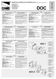
15 Position the Opener<br />
NOTE: A 25mm (1") board (1) is convenient for setting an ideal doorto-rail<br />
distance (unless headroom is not sufficient).<br />
Raise the opener onto a stepladder. Open garage door. Place a<br />
25mm (1") board (1) laid flat on the top section of door near the<br />
centerline as shown. Rest the rail on the board.<br />
If the raised door hits the trolley, pull down on the trolley release arm<br />
to disconnect the inner and outer trolley sections. The trolley can<br />
remain disconnected until connecting door arm to trolley is<br />
completed.<br />
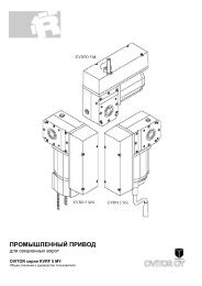
16 Hang the Opener<br />
The opener must be securely fastened to a structural support of<br />
the garage.<br />
Three representative installations are shown. Yours may be different.<br />
Hanging brackets (1) should be angled (Figure A) to provide rigid<br />
support. On finished ceilings, (Figure B) attach a sturdy metal bracket<br />
(not supplied) (4) to a structural support before installing the opener.<br />
For concrete ceiling mount, (Figure C), use concrete anchors (5)<br />
provided.<br />
On each side of opener measure the distance from the opener to the<br />
structural support (or ceiling).<br />
Cut both pieces of the hanging bracket to required lengths. Flatten<br />
one end of each bracket and bend or twist to fit the fastening angles.<br />
Do not bend at the bracket holes. Drill 4,5mm (3/16") pilot holes in<br />
the structural supports (or ceiling). Attach flattened ends of brackets<br />
to supports with wood screws (2).<br />
Lift opener and fasten to hanging brackets with screw, lock washer<br />
and nut (3). Check to make sure rail is centered over the door.<br />
Remove 25mm (1") board. Operate door manually. If door hits the<br />
rail, raise header bracket. Use rail grease and lubricate bottom<br />
surface of rail (6).<br />
17 Attach Emergency Release Rope &<br />
Handle<br />
Thread one end of rope (1) through hole in top of red handle so<br />
"NOTICE" reads right side up as shown (3). Secure with an overhand<br />
knot (2). Knot should be at least 25mm (1") from end of the rope to<br />
prevent slipping.<br />
Thread other end of rope through hole in release arm of the outer<br />
trolley (4). Adjust rope length so that handle is 1,8m (6 feet) above<br />
the floor. Secure with an overhand knot.<br />
NOTE: If it is necessary to cut rope, heat seal cut end with a match or<br />
lighter to prevent fraying.<br />
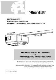
18 Install Light<br />
Press the release tabs on both sides of lens (2). Gently rotate lens<br />
back and downward until the lens hinge is in the fully open position.<br />
Do not remove the lens. Install a 40 watt (socket size E27), maximum<br />
light bulb (1) in the socket (3) as shown. The light will turn on and<br />
remain lit for 2-1/2 minutes when power is connected. After 2-1/2<br />
minutes it will turn off. Reverse the procedure to close the lens.<br />
Replace burned out bulbs with rough service light bulbs.<br />
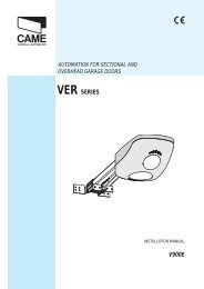
19 Install Lighted Door Control Button<br />
Locate push buttons where the garage door is visible (at a<br />
height of at least of 1,5m), away from door and door hardware<br />
and out of the reach of children.<br />
Serious personal injury from a moving garage door may result<br />
from misuse of opener. Do not allow children to operate the<br />
lighted door control button or remote control transmitter.<br />
Permanently fasten the caution label on the wall near the lighted<br />
door control button as a reminder of safe operating procedures.<br />
There are 2 screw terminals (1) on the back of the lighted door<br />
control button (2). Strip about 6mm (1/4") of insulation from bell wire<br />
(4). Separate wires enough to connect the white/red wire to terminal<br />
screw 1 and the white wire to terminal screw 2.<br />
Fasten the lighted door control button to an inside garage wall with<br />
sheet metal screws (3) provided. Drill 4mm (5/32") holes and use<br />
anchors (6) if installing into drywall. A convenient place is beside the<br />
service door and out of reach of children.<br />
Run the bell wire up the wall and across the ceiling to the garage<br />
door opener. Use insulated staples (5) to secure wire. The receiver<br />
quick connect terminals are located on the back panel of the opener.<br />
Connect the bell wire to the terminals as follows: white/red to red (7)<br />
and white to white (8).<br />
Operation of the Lighted Door Control Button<br />
Press to open or close the door. Press again to reverse the door<br />
during the closing or opening cycle.<br />
20 Fasten Door Bracket<br />
If yours is a canopy or dual-track one-piece style garage door, a door<br />
arm conversion kit is required. Follow the installation instructions<br />
included with the replacement door arm. Exercise care in removing and<br />
assembling arm conversion kit. Keep fingers away from the sliding<br />
parts.<br />
NOTE: Horizontal and vertical reinforcement is needed for lightweight<br />
garage doors.<br />
Sectional and One-Piece Door Installation Procedure:<br />
Door bracket (1) has left and right side fastening holes. Assemble<br />
and install the bracket and plate (2) if your installation requires top<br />
and bottom fastening holes.<br />
1. Center bracket (with or without plate, as required) at the top of<br />
inside face of door as shown. Mark holes.<br />
2. A. Wooden doors<br />
Drill 8mm holes (5/16") and fasten the door bracket with nut,<br />
lock washer, and carriage bolt (3) or use wood screws.<br />
B. Sheet metal doors<br />
Fasten with sheet metal screws (4).<br />
C. One-piece door optional<br />
Fasten with sheet metal screws (4).<br />
3-GB<br />
Connect Electric Power<br />
TO AVOID INSTALLATION DIFFICULTIES, DO NOT RUN THE<br />
GARAGE DOOR OPENER UNTIL INSTRUCTED TO DO SO.<br />
Connect the opener to a mains which is properly EARTHED<br />
according to the wiring instruction tag attached to power supply<br />
cord (and as specified by local code).<br />
114A2788C-GB