OBBI3BH
OBBI3BH
OBBI3BH

Create successful ePaper yourself
Turn your PDF publications into a flip-book with our unique Google optimized e-Paper software.
<strong>OBBI3BH</strong>IP1639 - rev. 2005-05-20IGBFDEPManuale di installazionee manutenzione perautomazioni per cancellia battente.Installation andMaintenance manual forswing gates.Manuel d’installation etd’entretien pour portes àbattant.Montage undWartungshandbuch fürDrehtorantriebe.Manual para la instalaciòny la manutenciòn paraautomatización paracancelas batientes.Instalação e Manutençãomanual para portões debalanço.DITEC S.p.A.Via Mons. Banfi , 3 - 21042 Caronno Pertusella (VA) - ITALYTel. +39 02 963911 - Fax +39 02 9650314www.ditec.it - ditec@ditecva.com
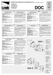
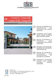
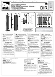
AEsempio nr. 1 - Example nr. 1 - Exemplenr. 1 - Beispiel Nr. 1 - Ejemplo nr. 1- Exemplo n. 1ECBB C 65Lmin120A 40DABC max(90°)DmaxELEsempio nr. 2 - Example nr. 2 - Exemplenr. 2 - Beispiel Nr. 2 - Ejemplo nr. 2 -Exemplo n. 1150 150 85 100° 75 910120 160 95 100° 75 910BC100120 180 115 110° 75 910A 25160 120 55 110° 75 910Fig. 3Esempio nr. 3 - Example nr. 3 - Exemplenr. 3 - Beispiel Nr. 3 - Ejemplo nr. 3 -Exemplo n. 110015BC1406850 min120A14Fig. 4 Fig. 53 Obbi 3BH - IP1639
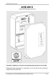
luebrownFig. 6 Fig. 7180°Fig. 8bluebrownFig. 9 Fig. 10Obbi 3BH - IP16394
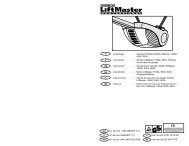
15G11 16 F 14604840Ø16Fig. 1110NH1312MFig. 12M2M1BlueCONTROLPANEL36 3433 31BlueFig. 13M1BlueCONTROLPANELM236 3433 31BlueFig. 145 Obbi 3BH - IP1639
GBGENERAL SAFETY PRECAUTIONSThis installation manual is intended for professionallycompetent personnel only.The installation, the electrical connections and the settings mustbe completed in conformity with good workmanship and with thelaws in force. Read the instructions carefully before beginningto install the product. Incorrect installation may be a source ofdanger. Packaging materials (plastics, polystyrene, etc) mustnot be allowed to litter the environment and must be kept out ofthe reach of children for whom they may be a source of danger.Before beginning the installation check that the product is inperfect condition. Do not install the product in explosive areas andatmospheres: the presence of flammable gas or fumes representsa serious threat to safety.Before installing the motorisation device, make all the structuralmodifications necessary in order to create safety clerance andto guard or isolate all the compression, shearing, trapping andgeneral danger areas. Check that the existing structure hasthe necessary strength and stability. The manufacturer of themotorisation device is not responsible for the non-observanceof workmanship in the costruction of the frames to be motorised, nor for deformations that may be occur during use. The safetydevices (photoelectric cells, mechanical obstruction sensor,emergency stop, etc) must be installed taking into account: theprovisions and the directives in force, good workmanship criteria,the installation area, the funtional logic of the system andthe forces developed by the motorised door or gate. The safetydevices must protect against compression, shearing, trappingand general danger areas of the motorized door or gate. Displaythe signs required by law to identify danger areas. Each installationmust bear a visible indication of the data identifying themotorised door or gate.Before connecting to the mains check that the rating iscorrect for the destination power requirements.A multipolar isolation switch with minimum contact gaps of 3 mmmust be included in the mains supply.Check that upstream of the electrical installation there is anadequate differential switch and a suitable circuit breaker.When requested, connect the motorized door or gate to aneffective earthing system carried out as indicated by currentsafety standards. During installation, maintenance and repairoperations, cut off the power supply before opening the coverto access the electrical parts.The electronic parts must be handled using earthed antistaticconductive arms. The manufacturer of the motorisingdevice declines all responsability in cases where componentswhich are incompatible with the safe and correct operation ofthe product only original spare parts must be used. For repairs orreplacements of products only original spare parts must be used.The fitter must supply all information corcerning the automatic,the manual and emergency operation of the motorised door orgate, and must provide the user the device with the operatinginstructions. It is recommended that antistatic conductive earthedarm bands be worn when manipulating electronic parts.MACHINE DIRECTIVEPursuant to Machine Directive (98/37/EC) the installer who motorisesa door or gate has the same obligations as a machinemanufacturer and shall:- prepare technical documentation containing the documentsindicated on Schedule V of the Machine Directive;(The technical documentation shall be kept and placed at thedisposal of competent national authorities for at least ten yearsstarting on the date of manufacture of the motorised door);- draw up the EC declaration of conformity according to ScheduleII-A of the Machine Directive;- affix the CE mark on the motorised door pursuant to para.1.7.3 of Schedule I of the Machine Directive.For more details, refer to the “Guidelines for producing technicaldocumentation” available on Internet at the following address:www.ditec.itAPPLICATIONS<strong>OBBI3BH</strong>Service life: 3 (minimum 10÷5 years of working life with 30÷60cycles a day)Applications: FREQUENT (For vehicle or pedestrian accessesto town houses or small condominiums with frequent use).- Performance characteristics are to be understood as referringto the recommended weight (approx. 2/3 of maximumpermissible weight). A reduction in performance is to be expectedwhen the access is made to operate at the maximumpermissible weight.- Service class, running times, and the number of consecutivecycles are to be taken as merely indicative having been statisticallydetermined under average operating conditions, and aretherefore not necessarily applicable to specific conditions ofuse. During given time spans product performance characteristicswill be such as not to require any special maintenance.- The actual performance characteristics of each automaticaccess may be affected by independent variables such asfriction, balancing and environmental factors, all of whichmay substantially alter the performance characteristics of theautomatic access or curtail its working life or parts thereof(including the automatic devices themselves). When settingup, specifi c local conditions must be duly borne in mind andthe installation adapted accordingly for ensuring maximumdurability and trouble-free operation.DECLARATION BY THE MANUFACTURER(Directive 98/37/EC, Annex II, sub B)Manufacturer: DITEC S.p.A.Address: via Mons. Banfi, 321042 Caronno Pertusella (VA) - ITALYHerewith declares that the electromechanical automatic systemseries OBBI:- is intended to be incorpored into machinery or to be assembledwith other machinery to constitute machinery converedby Directive 98/37/EC;- is in conformity with the provisions of the following other EECdirectives:Electromagnetic Compatibility Directive 89/336/EEC;Low Voltage Directive 73/23/EEC;and furthermore declares that it is not allowed to put the machineryinto service until the machinery into which it is to be incorporatedor of which it is to be a component has been found and declaredto be in conformity with the provisions of Directive 98/37/EC andwith national implementing legislation.Caronno Pertusella, 12/02/1998Fermo Bressanini(Chairman)OBBI - IP163910
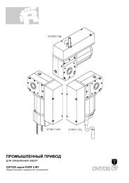
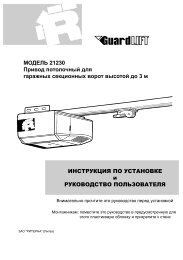
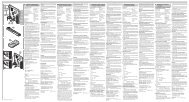
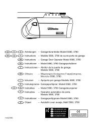
1. TECHNICAL DATA Obbi 3BHPower supply 24 V=AbsorptionMotor powerGeared motor torqueMax. stroke3 A24 W1500 N350 mmStroke time 25 s / 90°Intermittence S2= 30 min / S3= 50%TemperatureDegree of protectionWing dimensionm = door widthkg = door weightReccomendeddimensionsLimitdimensions-15° C / +50° CIP54m5.04.03.02.01.0kg100 300 500GB2. REFERENCE TO ILLUSTRATIONThe given operating and performance features can only be guaranteedwith the use of DITEC accessories and safety devices.2.1 Standard installation references (fig. 1)[1] Radio[2] Flashing light[3] Key selector[4] Connect power supply to a type-approved omnipolarswitchwith a contact opening gap of no less that 3 mm (not suppliedby us) protected against accidental and unauthorizedactivation.[5] Right geared motor[6] Left geared motor[7] Photocells[8] Electric board2.2 Geared motor reference (fig. 2-4)[9] Release[10] Housing[11] Draft tube[12] Tube cover[13] Closing plug[14] Tail bracket[15] Head bracket[16] Cable guide sheat hooking bracket3. INSTALLATION3.1 Preliminary checksCheck that the structure is suffi ciently sturdy and that the hingepivots are properly lubricated. Provide an opening and closingstop.Geared motor installationUnless otherwise specifi ed, all measurements are expressedin millimetres.3.2 Check the mounting dimensions (fi g. 3) as a function ofthe distance between the wing hinge pivot and the edgeof pillar [C] and of the desired opening angle [D].3.3 The geared motor is normally supplied in the right-handedversion. To convert it to the left-handed version, proceedas follows (see from Figs. 6 to 10):- Loosen the motor clamping screws (Fig. 6).- Remove the motor and the reduction gear plug, and slideout the motor cable (Fig. 7).- Rotate the reduction gear by 180 degrees (Fig. 8).- With the reduction gear in this position, fi t in the motorand the plug and route the cable in (Fig. 9).Attention: Take care to mount the motor so that the cablecomes to be on the opposite side of the release.- Fit in and secure the motor clamping screws (Fig. 10).3.4 Secure the tail bracket [14] (Fig. 4) according to dimensions[A] and [B] (shown in Fig. 3) selected as a function of thedesired opening angle [D]. The tail bracket is providedwith holes to facilitate mounting (fi g. 5).Note: The installation measurements given in the table in Figure3 permit to select the values for [A] and [B] according to thedesired opening angle and with reference to existing room andspaces. Compliance with themeasurement given in the table is recommended, modifying thebrackets provided, if so required.In order to ensure smooth gate movement, check that measurements[A] and [B] are the same. Increasing [A] reduces thecoming up speed during opening. Increasing [B] diminishes thecoming up speed during closing and improves burglar-proofi ng.Reducing [B] increases the extent of gate opening. Measurements[A] and [B] must in any case be compatible with the usefultravel of the piston so that; if [A] is increased, [B] must bediminished and vice versa.3.5 Fit the piston onto tail bracket [14] by means of the pin [F]provided (fi g. 11).3.6 Unscrew the piston draft tube [11] out to its full length andretighten it of approx. 20 mm (see dimension [L] of fi g. 3).Attention: The stops must be such as to ensure a drafttube travel margin of 10 mm both with closed and opengate wings.3.7 When the gate is completely closed, position the headbracket [15], check that it and tail bracket are perfectlylevel and secure it to the gate (fi g. 4).11 CUBIC - IP1639
GB 3.8 Fit the piston onto head bracket by means of the pin [G]provided (fig.11). For correct operation, the geared motorsmust be mounted with the motor housing at the top.3.9 Release the geared motor (see RELEASING and LOCK-ING Instructions) and move the gate by hand to check forsmooth movement throughout. Slightly lubricate front andrear joints.3.10 Fit the tube cover [12] with the plug [13] and gasket andsecure it to the geared motor by means of the screw [H]and [M] provided (fi g. 12). Fit properly, making sure thatthe slits on the closing plug [13] are turned downwards soas to favour water drain-off.3.11 Secure the casing [10] into place by means of screw [N]paying attention to the position of the wire (fi g. 12).4. ELECTRICAL CONNECTIONSThe electrical connections and the startup of the Obbi 3BH areillustrated in fi g. 13 and 14 and in the installation manuals of thecontrol panel D2H and Logic C22/C22S.5. MAINTENANCE PROGRAM (each 6months)Power off (230 V~ mains and batteries, if installed):- Lubricate front and rear joints.- Lubricate the gate leaf hinges.- Check the good conditions of the electric connection.- Check that the fi xing screws of the geared motor are fi rmlytightened.Power on 230 V~ mains and batteries:- Check the power adjustment.- Check the good operation of all command and safety functions(photocells).- Check the good operation of the release system.ATTENTION: For spare parts, see the spares price list.All right reservedAll data and specifi cations have been drawn up and checkedwith the greatest care. The manufacturer cannot however takeany responsibility for eventual errors, ommisions or incompletedata due to technical or illustrative purposesOBBI - IP163912
INSTRUCTIONS FOR THE USE OF AUTOMATION FOR OBBI SWING GATESGBAttention: Lock and release operations must be performed withmotor not running.LEFT PISTONRELEASE INSTRUCTIONIn case of faulty operation or power failure, unlock the electriclock, if mounted, insert the key and rotate the key anticlockwise(as indicated by the arrow on the geared motor). Manually slidethe gate open.LOCK INSTRUCTIONTo relock the wings, turn the key clockwise (counterwise to thedirection of the arrow on the geared motor). To facilitate theoperation, slightly move the gate wing.TEAR OFF AND DELIVER TO USERGENERAL SAFETY PRECAUTIONSThe following precautions are an integral and essentialpart of the product and must be supplied to the user. Readthem carefully as they contain important indications for the safeinstallation, use and maintenance. These instruction must bekept and forwarded to all possible future user of the system.This product must be used only for that which it has been expresslydesigned. Any other use is to be considered improperand therefore dangerous. The manufacturer cannot be held responsiblefor possible damage caused by improper, erroneous orunreasonable use. Avoid operating in the proximity of the hingesor moving mechanical parts. Do not enter the fi eld of action ofthe motorised door or gate while in motion.Do not obstruct the motion of the motorised door or gate as thismay cause a situation of danger. Do not allow children to play orstay within the field of action of the motorised door or gate. Keepremote control or any other control devices out of the reach ofchildren, in order to avoid possible involuntary activation of themotorised door or gate.In case of break down or malfunctioning of the product, disconnectfrom mains, do not attempt to repair or intervene directlyand contact only qualifi ed personnel.Failure to comply with the above may create a situation ofdanger.All cleaning, maintenance or repair work must be carried outby qualified personnel.In order to guarantee that the system works effi ciently andcorrectly it is indispensable to comply with the manufacturer’sindications thus having the periodic maintenance of the motoriseddoor or gate carried out by qualifi ed personnel.In particular regular checks are recommended in order to verifythat the safety devices are operating correctly. All installation,maintenance and repair work must be documented and madeavailable to the user.RIGHT PISTONONOFFDITEC S.p.A.Via Mons. Banfi , 321042 Caronno Pertusella (VA) - ITALYTel. +39 02 963911 - Fax +39 02 9650314www.ditec.it - ditec@ditecva.comInstaller:
DITEC S.p.A.Via Mons. Banfi , 321042 Caronno P.lla (VA)ITALYTel. +39 02 963911Fax +39 02 9650314www.ditec.itditec@ditecva.comQuarto d’Altino (VE)Caronno Pertusella (VA)DITEC BELGIUMLOKERENTel. +32 (0)9 356 00 51Fax +32 (0)9 356 00 52www.ditecbelgium.beDITEC DEUTSCHLANDOBERURSELTel. +49 6171914150Fax +49 61719141555www.ditec-germany.deLokerenOberurselDITEC FRANCEPALAISEAUTel. +33 1 64532860Fax +33 1 64532861www.ditec.frDITEC SVIZZERAMENDRISIOTel. +41 91 6463339Fax +41 91 6466127www.ditecswisse.chPalaiseauMendrisioDITEC AMERICAORLANDO - FLORIDA - U.S.A.Tel. +1 407 8880699Fax +1 407 8882237www.ditecamerica.comOrlando
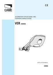
D2HManuale di installazione quadro elettrico per cancelli Obbi3BH a 1 o 2 motori 24 V=Electric board installation handbook for Obbi3BH gate with 1 or 2 motors 24 V=Manuel d'installation armoire électrique pour portails Obbi3BH à 1 our 2 moteurs 24 V=Steuerung Montagehandbuch für Drehtore Obbi3BH mit 1 oder 2 Motoren 24 V=Manual de instalaciòn cuadro electrico para cancelas Obbi3BH 1 o 2 motor 24 V=Q.E. D2HSOL NF1BATONOFFF21234OMPOWERSATM TC TR R136 34 33 31 15 1413 0 0 1 1 5 6 8 9RADIO / OPEN230 V~M2BATTERY KITBATK1M1- +24 V= / 0.3 AFig. 1F1 = F1.6 A linea / line / secteur /Leitung / lineaF2 = F2.5 A accessori / accessories /accessoires / Zubehör /accessoriosOM1 motore / 1 motor36 34 33 31M14.5 A maxFig. 2IP1586 27-09-2002DITEC S.p.A.Via Mons. Banfi, 321042 Caronno P.lla (VA) ItalyTel.+39 02 963911 - Fax +39 02 9650314www.ditec.itISO 9001 - Cert. n° 0957/1
GENERAL SAFETY PRECAUTIONSThis installation manual is intended for professionaly competent personnel only.The installation, the electrical connections and the settings must be completed in conformity with good workmanshipand with the laws in force. Read the instructions carefully before beginning to install the product. Incorrectinstallation may be a source of danger.Packaging materials (plastics, polystyrene, etc) must not be allowed to litter the environment and must be keptout of the reach of children for whom they may be a source of danger. Before beginning the installation check thatthe product is in perfect condition.Do not install the product in explosive areas and atmospheres: the presence of flammable gas or fumes representsa serious threat to safety. The safety devices (photoelectric cells, mechanical obstruction sensor, emergencystop, etc) must be installed taking into account: the provisions and the directives in force, good workmanshipcriteria, the installation area, the funtional logic of the system and the forces developed by the motorised dooror gate.Before connecting to the mains check that the rating is correct for the destination power requirements.A multipolar isolation switch with minimum contact gaps of 3 mm must be included in the mains supply.Check that upstream of the electrical installation there is an adequate differential switch and a suitable circuitbreaker.When requested, connect the motorized door or gate to an effective earthing system carried out as indicated bycurrent safety standards. During installation, maintenance and repair operations, cut off the power supply beforeopening the cover to access the electrical parts.The electronic parts must be handled using earthed antistatic conductive arms. The manufacturer of the motorisingdevice declines all responsability in cases where components which are incompatible with the safe and correctoperation of the product only original spare parts must be used. For repairs or replacements of products only originalspare parts must be used. The fitter must supply all information corcerning the automatic, the manual and emergencyoperation of the motorised door or gate, and must provide the user the device with the operating instructions. It isrecommended that antistatic conductive earthed arm bands be worn when manipulating electronic parts.INSTALLATION WARNINGSecure the electric board permanently. Drill the lower side of the container so as to run the cables through it.Secure the cables, if they are accessible, by means of appropriate gland plates (not provided by us). Keep the lineconductors separate (at least 8 mm.) from the control conductors and motor at the terminal board connectionpoints (for example, by means of clamps). Re-close the container by means of the 4 screws, taking care toproperly position the cover (lower side = Devoid of gasket).ENGLISHTECHNICAL DATAPower supplyMotor outputSafety accessories power supply(nominal)(peak)TemperatureDegree IPDimensionsD2H230 V~ / 50 Hz24 V= / 2 x 4.5 A (max)24 V= / 0.3A24 V= / 0.5A-15 °C / +50 °CIP54180x250x100All right reservedAll data and specifications have been drawn up and checked with the greatest care. The manufacturer cannot however take anyresponsibility for eventual errors, ommisions or incomplete data due to technical or illustrative purposes5 DITEC S.p.A. - IP1586 - D2H
1. ELECTRICAL CONNECTIONWARNING:1.1 ControlsLink up all N.C. contacts (if not used) by means of jumpers.The terminal bearing the same number are equivalent.The given operating and performance features can only be guaranteed with the use of DITECaccessories and safety devices.ENGLISHCONTROL FUNCTION DESCRIPTION1 5 N.O. STEP BY STEP When DIP1 = OFF sequence:“Open-Stop-Close-Open”.Warning: if the automatic closure is enabled, the stop isnot permanent but lasts for the time set by means of TC.When DIP1 = ON and automatic closing is activated, contact1-5 = “Open”.When DIP1 = ON and automatic closing is deactivated,contact 1-5 executes the opposite movement of the onethat was executed prior to stopping when the gate is standingstill. Note: with permanent contact 1-5, the automaticclosing is disabled until the contact reopens.1 6 N.C. STOPPING SAFETY CONTACT It stops or prevents the any operation.1 8 N.C. REVERSAL SAFETY CONTACT Reverses the direction of movement during the closingmaneuver (opens the gate again). When the gate isstanding still and bridge SO is closed, every movement– both opening and closing – is prevented. When thegate is standing still and bridge SO is interrupted, onlythe closing maneuver is prevented.1 9 N.C. STOP With the 1-9 contact, the gate stops or stays stopped andautomatic closing is disabled.RADIO / OPEN STEP BY STEP It has the same function as contact 1-5.1.2 Outputs and accessoriesOutput Value Description1 + 24V = / 0.3 A (nominal) Accessories power supply. Output for power external accessories0 - 0.5 A (peak) including the door-open signal lamp. Electronically-protected exit.0 14 24V = / 30 W max. Flashing light (LAMPH). It is activated during the opening and closingmovements. During an automatic closing procedure the blinking phasebegins 3 s before the time set on TC expires; if TC is set to less than 3 s, thepreliminary blinking phase continues throughout the entire standstill time.Protected exit with fuse F2.0 15 24V = / 1.2 A max. Electric lock. In connection with an electric lock having 12V the resistanceof 8.2 Ohm/5 W is connected in series. It is activated at the beginning ofevery opening movement. When DIP 3 = ON, the release can be activated.Protected exit with fuse F2.1 13 24V = / 3 W max. Light „Gate open“. Activates a light that goes out only when the gate isclosed.MotorconnectionBATWhen there are double-leaf gates, connect the motors according to Fig.1. Note: Depending on the direction of opening of the leaves of the gate,the polarity of the motor may have to be reversed.When there are single-leaf gates, bridge OM has to be interrupted andthe motor should be connected according to Fig. 2. Note: If it is necessaryto lengthen the motor cable, use 2x1.5 mm² up to a length of 15 m;then increase the cross-section proportionally to the distance.This connection is provided for connecting an optional emergency battery(BATK1, equipped with a control circuit and charging device) to ensurethat the opening system functions in the event of a power failure.DITEC S.p.A. - IP1586 - D2H6
1.3 Settings and adjustmentTC Automatic closure time. From 0 to 120 s when TC is set from 0 to 3/4 rotations. The counting beginswhen the gate is closed and continues throughout the entire duration of time set on TC.When DIP2 = OFF and after response of a safety device (1-6/1-8), the counting begins after the safety deviceitself is released (e.g. after passing through the light barrier) and takes half as long as the time set on TC.With DIP2=ON the count begins when the gate is open and lasts for the entire length of time set on TC.When TC is in the maximum position or contact 1-9 is open, the automatic closing procedure is deactivated.When the deactivation is executed via 1-9, the automatic closing procedure will only be activated again aftercontact 1-9 is closed again, if command 1-5 is given.TM Maximum operating time. From 10 to 90 s when TM is set between minimum and maximum setting.TR Setting for the delay time of motor 1 during the closing procedure. From 0 to 30 s when TR is setbetween minimum and maximum. During the opening procedure motor 2 (M2) always starts 3s after M1.During the closing procedure motor 1 (M1) is started after M2, with such delay being set via TR.R1 Obstacle detection adjustment. The control unit must be equipped with a safety device that interrupts the openingor closing procedure when an obstacle is detected. When R1 is set to minimum, the system exhibits minimumpower and maximum sensitivity with respect to obstacles. When R1 is in the maximum setting, the system exhibitsmaximum power and minimum sensitivity with respect to obstacles.DIP1DIP2DIP3Command 1-5 functioning = step by stepOFF / ON /Command 1-5 functioning = opensResetting the automatic closing time = 50% Resetting the automatic closing time = 100%Electric lock release = disabledElectric lock release = abledENGLISHDIP4(*)SOOMCondition of the gate when the motor is switched on Condition of the gate when the motor is switched= gate open: the first command 1-5 executes a closing on = gate closed: the first command 1-5 executesprocedure. (Note: When DIP1 = ON and TC is not set to an opening procedure. (Note: The automatic closingprocedure may not be the first command, even ifthe maximum setting, the first command executes onlythe automatic closing procedure).it is activated).Safety device 1-8 funtioning: opening contact 1-8 Safety device 1-8 functioning: opening contact 1-prevents any kind of maneuver when the gate is 8 permits an opening procedure via command 1-5standing still.when the gate is standing still.Number of leaves: Gate with two leaves. Number of leaves: Gate with one leaf.(*) DIP4 indicates the condition, in which the control unit considers the gate to be when the motor is switched on (orwhen the power supply is restored after a power failure) irrespective of the actual position of the leaves of the gate.LED POWER. When this LED lights up, it means that the control unit is being supplied with power.LED SA. When this LED lights up, it means that at least one of the contacts 1-6, 1-8 (safety devices) or 1-9 (Stop) is open.2. STARTCAUTION:The movements described in 2.4 are executed without any safety devices.The trimmers can only be adjusted when the gate is standing still.2.1 Close the leaves of the gate manually.2.2 In case of a single-leaf gate, interrupt bridge OM.2.3 Set TC and R1 to the maximum settings. Bypass safety devices and stop.2.4 Switch on the power supply. (Note: Depending on the direction of opening of the leaves, the polarity of the motor mayhave to be reversed.). When the opening maneuver is defined by a limit stop, trimmer TM should be set in such a waythat the time of the moving procedure takes 2-3 s longer than the time required for the gate to be opened completely.When the opening maneuver is not defined by a limit stop, trimmer TM should be set in such a way that the desireddistance of opening is reached. Set trimmer TR in such a way that the leaves of the gate close again by folding overone another correctly (also when the direction is reversed). Check that the gate is functioning correctly by means ofconsecutive step commands (Open-Stop-Close).2.5 Interrupt bridges, connect the contacts, safety devices (1-6 and 1-8) as well as the stop (1-9) and checkwhether everything is functioning correctly.2.6 If necessary, set the automatic closing procedure via trimmer TC. Attention: The time for the automaticclosing procedure after the safety device has responded depends on the setting selected for DIP2.2.7 Set the sensitivity of the obstacle recognition by means of R1.2.8 Connect any accessories, if applicable, and check whether they function correctly.2.9 Re-close the container by means of the 4 screws, taking care to properly position the cover (lower side =Devoid of gasket).7 DITEC S.p.A. - IP1586 - D2H