OBBI3BH
OBBI3BH
OBBI3BH

Create successful ePaper yourself
Turn your PDF publications into a flip-book with our unique Google optimized e-Paper software.
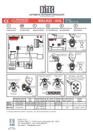
1. ELECTRICAL CONNECTIONWARNING:1.1 ControlsLink up all N.C. contacts (if not used) by means of jumpers.The terminal bearing the same number are equivalent.The given operating and performance features can only be guaranteed with the use of DITECaccessories and safety devices.ENGLISHCONTROL FUNCTION DESCRIPTION1 5 N.O. STEP BY STEP When DIP1 = OFF sequence:“Open-Stop-Close-Open”.Warning: if the automatic closure is enabled, the stop isnot permanent but lasts for the time set by means of TC.When DIP1 = ON and automatic closing is activated, contact1-5 = “Open”.When DIP1 = ON and automatic closing is deactivated,contact 1-5 executes the opposite movement of the onethat was executed prior to stopping when the gate is standingstill. Note: with permanent contact 1-5, the automaticclosing is disabled until the contact reopens.1 6 N.C. STOPPING SAFETY CONTACT It stops or prevents the any operation.1 8 N.C. REVERSAL SAFETY CONTACT Reverses the direction of movement during the closingmaneuver (opens the gate again). When the gate isstanding still and bridge SO is closed, every movement– both opening and closing – is prevented. When thegate is standing still and bridge SO is interrupted, onlythe closing maneuver is prevented.1 9 N.C. STOP With the 1-9 contact, the gate stops or stays stopped andautomatic closing is disabled.RADIO / OPEN STEP BY STEP It has the same function as contact 1-5.1.2 Outputs and accessoriesOutput Value Description1 + 24V = / 0.3 A (nominal) Accessories power supply. Output for power external accessories0 - 0.5 A (peak) including the door-open signal lamp. Electronically-protected exit.0 14 24V = / 30 W max. Flashing light (LAMPH). It is activated during the opening and closingmovements. During an automatic closing procedure the blinking phasebegins 3 s before the time set on TC expires; if TC is set to less than 3 s, thepreliminary blinking phase continues throughout the entire standstill time.Protected exit with fuse F2.0 15 24V = / 1.2 A max. Electric lock. In connection with an electric lock having 12V the resistanceof 8.2 Ohm/5 W is connected in series. It is activated at the beginning ofevery opening movement. When DIP 3 = ON, the release can be activated.Protected exit with fuse F2.1 13 24V = / 3 W max. Light „Gate open“. Activates a light that goes out only when the gate isclosed.MotorconnectionBATWhen there are double-leaf gates, connect the motors according to Fig.1. Note: Depending on the direction of opening of the leaves of the gate,the polarity of the motor may have to be reversed.When there are single-leaf gates, bridge OM has to be interrupted andthe motor should be connected according to Fig. 2. Note: If it is necessaryto lengthen the motor cable, use 2x1.5 mm² up to a length of 15 m;then increase the cross-section proportionally to the distance.This connection is provided for connecting an optional emergency battery(BATK1, equipped with a control circuit and charging device) to ensurethat the opening system functions in the event of a power failure.DITEC S.p.A. - IP1586 - D2H6