Cross14, Cross14E, Cross14VE, Cross15V
Cross14, Cross14E, Cross14VE, Cross15V
Cross14, Cross14E, Cross14VE, Cross15V
- No tags were found...

You also want an ePaper? Increase the reach of your titles
YUMPU automatically turns print PDFs into web optimized ePapers that Google loves.
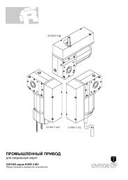
1. TECHNICAL DETAILSPower supply230 V~ / 50 HzCurrent3 AMotor power350 WThrust1200 NSpeed0.2 m/sMax stroke11 mMax wing weight1400 kgService class4 - INTENSIVEMin. num. of consecutive cycles 50IntermittencyS2=30min/S3=50%Temperature-20° C / +55° CDegree of protectionIP54Weight19 kgControl panelE1ALimit switchROTARY(*) Control panel installed on board.2. REFERENCES TO ILLUSTRATIONSThe given operating and performance features can only be guaranteedwith the use of DITEC accessories and safety devices.2.1 Standard installation references (fig. 1)[1] Radio transmitter[2] Flashing light[3] Key selector[4] Connect power supply to an omnipolar switch with acontact opening gap of no less than 3 mm (not suppliedby us).Connection to supply mains must be carried out in anindependent raceway separate from control connections andsafety device connections.[5] Rubber edge / Sensitive edge[6] Gearmotor + Control panel (only <strong>Cross14</strong>E-14VE)[7] Photocells2.2 Geared motor references (fig. 3,11,12)[8] Gearmotor[9] Casing[10] Control panel[11] Manual lock release[12] Rotatory limit-switch group[13] Lever limit-switch group[14] Magnetic limit-switch group[15] Pinion[16] Pinion casing[17] Rack guide bracket[18] Magnetic limit switch bracket[19] Lever limit switch bracket2.3 AccessoriesCross CRI Galvanized steel rackCross TC Chain drive kitCat1 Chain 1/2" (5 m)CatGCoupling for 1/2" chain3. INSTALLATIONUnless otherwise specified, all measurements are expressedin millimetres (mm).3.1 Preliminary checksCheck for gate stability (derailment and sideways falling), thatthe slide wheels are in good condition and that the top guidesdo not cause any friction.The sliding track must be securely anchored to the groundand fully exposed along its full length.<strong>Cross14</strong> <strong>Cross14</strong>E <strong>Cross14</strong>VE <strong>Cross15V</strong>230 V~ / 50 Hz 230 V~ / 50 Hz3 A3 A350 W350 W1200 N1200 N0.2 m/s0.2 m/s16 m16 m1400 kg1400 kg4 - INTENSIVE 4 - INTENSIVE5050S2=30min/S3=50% S2=30min/S3=50%-20° C / +55° C -20° C / +55° CIP54IP5419 kg19 kgE1A*E1A*LEVERMAGNETICIt must be perfectly smooth so as to avoid jamming of the gate.Provide opening and closing stops.N.B.: Make sure that the gate is securely inserted in the slidewayso that it cannot come out of the slideway and fall.In case of slits being present on the gate, cover them to avoidany risk of cutting.To reduce impact force installation of safety devices at gateends is recommended3.2 Base plate prearrangement- Insert the anchoring brackets into the base plate andsecure them by means of the nuts provided.(*) CROSS CRI(*) X+20(**) 70130Ø12.5 x 2min24060 270240270SXØ 50 x 2130400 V~ / 50 Hz1.2 A450 W1500 N0.2 m/s16 m1500 kg4 - INTENSIVE50S2=30min/S3=50%-20° C / +55° CIP5416 kgLogicTMAGNETICØ12.5 x 2X = 40 mm(**) CROSSTC 70 mmØ 50 x 2min150X+20 (*)70 (**)GB11 DITEC S.P.A - IP1732 - <strong>Cross14</strong>-15
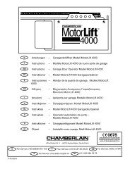
GB- Lay a concrete foundation with buried anchoring bracketsand the base plate, making sure it is perfectly levelledand smooth, complying with the measurements shown infigure.If a concrete foundation is already available, secure thebase plate by means of appropriate dowels (not suppliedby us) so as to allow height adjustment.- Route the cable ducts through one of the two holes in themiddle of the plate.3.3 Geared motor installation- Release the gearmotor and remove the key. Loosen thetwo frontal screws and remove the casing [9].- Position the gearmotor onto the base plate.- Gearmotor adjustmentsHorizontally by making gearmotor slide along theanchoring brackets notches (max 10 mm). Vertically withthe 4 levelling screws [F]N.B.: While adjusting vertically, keep the motor slightlyraised above the base plate so as to allow enough spaceto secure the rack and to make any subsequentadjustments, if necessary.3.4 Rack installation- Release the gearmotor (see OPERATINGINSTRUCTIONS) and set the gate in the open position.Place the rack on the pinion [15] and move the gatemanually to secure the rack along its full length.- Once the rack has been secured, vertically adjust thegearmotor so as to have a gap of 2 - 3 mm between thepinion and the rack and a gap of approximately 3 mm betweenthe rack and the rack guide bracket (only <strong>Cross14</strong>).<strong>Cross14</strong> only2÷3~ 3D EX11010F10F- Firmly secure the gearmotor by means of nuts [D].- Lubricate the rack and pinion lightly after assembly.Manually move gate to check that it slides freely andsmoothly.3.5 Lever limit switch adjustment1026637- Manually position the door wing completely open andfasten the limit switch brackets [19] onto the rack so thatthe lever limit switch exceeds the bracket’s length byapproximately 2/3. Repeat the operation with door wingcompletely closed.- After having performed a certain number of operations,adjust the position of the limit switch bracket [19] so thatthe gate will stop about 20 mm before the opening andclosing stops.D E40191910F10FCrossTC15-20 mm19191026648DITEC S.P.A - IP1732 - <strong>Cross14</strong>-1512
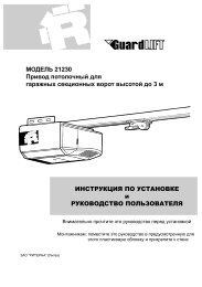
3.6 Magnetic limit switch adjustment- Manually position the door wing completely open andfasten the limit switch brackets [18] onto the rack so thatthe lever limit switch exceeds the bracket’s length byapproximately 2/3. Repeat the operation with door wingcompletely closed.- After having performed a certain number of operations,adjust the position of the limit switch bracket [18] so thatthe gate will stop about 20 mm before the opening andclosing stops.~20GB15-20 mm181818183.7 Rotatory limit switch adjustment- With the gate open, turn screw [A] so that cam [M]activates the opening microswitch. With gate closed, turnscrew [C] so that cam [L] activates the closingmicroswitch.N.B. : For gates that open on the left-hand side (gearmotorside view), the limit stop microswitches are inverted [A]for closing and [C] for opening.- Adjust [A] and [C] so that the limit switches trip cut off themotor about 20 mm before the gate reaches the gate stops.N.B.: Check this is still happening after having performeda certain number of operations.LM13 DITEC S.P.A - IP1732 - <strong>Cross14</strong>-15
GB3.8 CrossTC INSTALLATION for Cross 14 (for Cross 14)Disengage the gearmotor (see OPERATING INSTRUCTIONS).Remove the pinion [15] and the rack guide bracket [17]. Fixthe pinion-holding plate to the gearmotor. Fit the pinions asshown in the figure. Manually route the chain through thepinions. Fix the cover plate.Attention: With chain fitted, the gearmotor direction of rotationis reversed.4. ELECTRICAL CONNECTIONElectrical wiring and starting are shown in the installation manualof Control Panel E1A.Attention: for motor's and limit-swich connection, see figure 4,5, and 6.WARNING: connect the yellow-green ground cable to the clampalready connected to the motor, as it is shown in the figure.5. MAINTENANCE PROGRAM (each 6 month)3.9 Chain installation- Set the gate in the open position and fasten brackets [G]to the wing as shown in figure.40X- Connect the chain previously installed on the gearmotorto the tie rod [H] and fasten it to the bracket [G].- Secure the bracket [G] onto the opposite side of the gate.Connect the chain to the tie rod [H] and secureit to the bracket [G] (cut off excess chain).With the gate in complete opening and closing position,check that the distance between the centre of the pinion[X] and the tie rod [H] shown in figue is respected.HGPower off and geared motor released (see OPERATINGINSTRUCTIONS):- Visually check that the gate, anchoring bracket and existingstructure are sufficiently sturdy and in good condition.- Check gate/gearmotor alignment and the distance (2-3mm) between the mouth of the pinion and the crest of therack and check the distance from the rack to the rackguide bracket (3 mm), if fitted.- Clean the wheel sliding tracks, lightly lubricate the pinion,the rack or the chain. Manually move gate to check that itslides freely and smoothly.Power on and geared motor lock (see OPERATINGINSTRUCTIONS):- Check the functioning of the limit switches (the gate mustcome to a halt about 20 mm before the stops).- Check the power adjustments.- Check the operation of all controls and safety functions.ATTENTION: For spare parts, see the spares price list.min. 60H110X- Finally, firmly secure the gearmotor by means of nuts [D].- Tighten the chain by means of tie rods [H].- Lightly lubricate the chain and pinion after assembly.DITEC S.P.A - IP1732 - <strong>Cross14</strong>-1514
OPERATING INSTRUCTION FOR SLIDING GATESGBRELEASE INSTRUCTIONIn case of fault or power failure, insert and turn the keyanticlockwise, completely open the cover. Manually open thegate. To lock the gate again, shut the cover, turn the keyclockwise and remove the key .Attention: Perform locking and lock release operationswith motor cut off.Attention: With the cover closed and the key in a horizontalposition, the lock release microswitch is open, thus preventingany operation.90˚GENERAL SAFETY PRECAUTIONSThe following precautions are an integral and essentialpart of the product and must be supplied to the user.Read them carefully as they contain important indications forthe safe installation, use and maintenace.These instruction must be kept and forwarded to all possiblefuture user of the system.This product must be used only for that which it has beenexpressely designed.Any other use is to be considered improper and thereforedangerous.The manufacturer cannot be held responsible for possibledamage caused by improper, erroneous or unresonable use.Avoid operating in the proximity of the hinges or movingmechanical parts.Do not enter the field of action of the motorised door or gatewhile in motion.Do not obstruct the motion of the motorised door or gate as thismay cause a situation of danger.Do not lean against or hang on to the barrier when it is moving.Do not allow children to play or stay within the field of action ofthe motorised door or gate.Keep remote control or any other control devices out of thereach of children, in order to avoid possible involuntary activationof the motorised door or gate.In case of breack down or malfunctioning of the product,disconnect from mains, do not attempt to repair or intervenedirectly and contact only qualified personnel.Failure to comply with the above may create a situation ofdanger.All cleaning, maintenance or repair work must be carried out byqualified personnel.In order to guarantee that the system works efficiently andcorrectly it is indispensable to comply with the manufacturer’sindications thus having the periodic maintenance of themotorised door or gate carried out by qualified personnel.In particular regular checks are recommended in order to verifythat the safety devices are operating correctly. All installation,maintenance and repair work must be documented and madeavailable to the user.TEAR OFF AND DELIVER TO USERONOFF90˚OFFONInstaller:DITEC S.p.A.Via Mons. Banfi, 321042 Caronno Pertusella (VA) - ITALYTel. +39 02 963911 - Fax +39 02 9650314www.ditec.it - ditec@ditecva.com
DITEC S.p.A.Via Mons. Banfi, 321042 Caronno P.lla (VA)ITALYTel. +39 02 963911Fax +39 02 9650314www.ditec.itditec@ditecva.comQuarto d’Altino (VE)Caronno Pertusella (VA)DITEC BELGIUMLOKERENTel. +32 (0)9 356 00 51Fax +32 (0)9 356 00 52www.ditecbelgium.beDITEC DEUTSCHLANDOBERURSELTel. +49 6171914150Fax +49 61719141555www.ditec-germany.deLokerenOberurselDITEC FRANCEPALAISEAUTel. +33 1 64532860Fax +33 1 64532861www.ditec.frDITEC SVIZZERAMENDRISIOTel. +41 91 6463339Fax +41 91 6466127www.ditecswisse.chPalaiseauMendrisioDITEC AMERICAORLANDO - FLORIDA - U.S.A.Tel. +1 407 8880699Fax +1 407 8882237www.ditecamerica.comOrlando