ACM 400 S
ACM 400 S
ACM 400 S
- No tags were found...

Create successful ePaper yourself
Turn your PDF publications into a flip-book with our unique Google optimized e-Paper software.
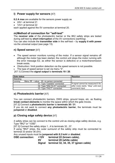
<strong>ACM</strong> <strong>400</strong> S motor control unitl) Power supply for sensors [X7]0.2 A max are available for the sensors power supply as• 24V~ at terminal 21• 12V= at terminal 22each applied against the 0V connection at terminal 20.m) Method of connection for "self-test"The receiver side of the photoelectric barrier or the 8K2 safety strips are testedduring self-test by short interruption of the 0V connections (earthing).You can also include the transmitter side in the self-test – by supply it with powervia the universal output (see page 13).n) Speed sensor [X7]• The speed sensor monitors running of the motor. If a sensor signal remains offalthough the motor has been started, the control unit stops the motor running withthe error message E2, as either the sensor is defective or a motor/transmissionbreak exists.• Obstruction / limit position detection via the speed sensors is not possible.• The type of speed sensor is set via menu “0”.[X7.1] Connect the signal output to terminals 19 / 20.Gate statusReactionStanding -running Menu “0“ – value: 00 no sensor connected -01 Type "Castalia" connected02 Type "DSLTA-51" connected03 Type "FACT" connectedIf signal cannot be measured 0.5safter motor starts: “Stop“ until nextcommand inputo) Photoelectric barrier [X7]You can connect photoelectric barriers, DWG strips, ground loops, etc. as floatingbreak contact elements to monitor the space within which the gate moves.[X7.2] Connect a photoelectric barrier to terminals 30 / 31.If you do not want to connect any photoelectric barrier, the terminals must bejumpered or disabled.p) Closing edge safety device [X7]4 safety strips can be connect to the control unit as closing edge safety devices, e.g.Type "8K2" or "-OSE".[X7.3] Connect the safety strips 1...4 to terminals 32...37.If using "8K2" strips, the outer surround of the safety strip must be connected toterminal 33 and/or 36 (0V).Any unused inputs must be jumpered with 8.2 kohl or disabled.OSE connection: +12V terminal 22 (brown cable),0V terminal 20 (white cable)Signal terminal 32, 34, 35, 37 (green cable)11 / 24