

2.3 Relaxatie-oscillator
2.3 Relaxatie-oscillator
2.3 Relaxatie-oscillator

You also want an ePaper? Increase the reach of your titles
YUMPU automatically turns print PDFs into web optimized ePapers that Google loves.
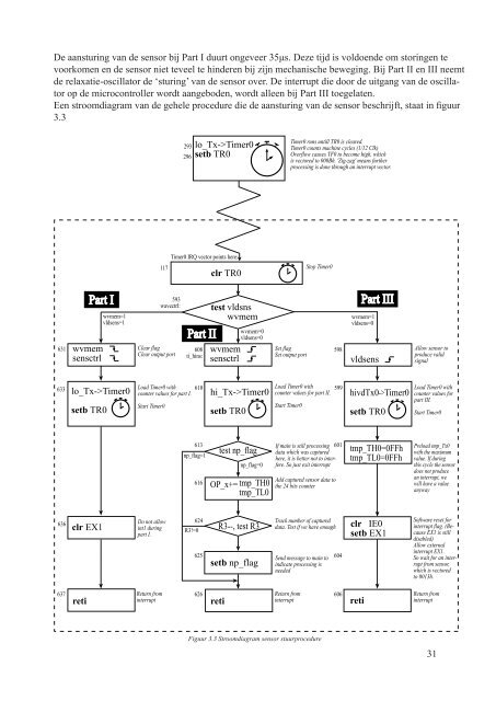
De aansturing van de sensor bij Part I duurt ongeveer 35μs. Deze tijd is voldoende om storingen te<br />
voorkomen en de sensor niet teveel te hinderen bij zijn mechanische beweging. Bij Part II en III neemt<br />
de relaxatie-<strong>oscillator</strong> de ‘sturing’ van de sensor over. De interrupt die door de uitgang van de <strong>oscillator</strong><br />
op de microcontroller wordt aangeboden, wordt alleen bij Part III toegelaten.<br />
Een stroomdiagram van de gehele procedure die de aansturing van de sensor beschrijft, staat in figuur<br />
3.3<br />
631<br />
633<br />
636<br />
637<br />
Part I<br />
clr TR0<br />
test vldsns<br />
wvmem<br />
wvmem<br />
Clear flag<br />
608 wvmem<br />
Set flag<br />
598<br />
Clear output port<br />
sensctrl ti_hins:<br />
Set output port<br />
sensctrl<br />
vldsens<br />
lo_Tx->Timer0<br />
setb TR0<br />
clr EX1<br />
wvmem=1<br />
vldsens=1<br />
117<br />
593<br />
wavectrl:<br />
Load Timer0 with<br />
counter values for part I.<br />
Start Timer0<br />
Do not allow<br />
int1 during<br />
part I.<br />
Return from<br />
293 lo_Tx->Timer0<br />
296 setb TR0<br />
Timer0 IRQ vector points here:<br />
Part II<br />
610<br />
613<br />
np_flag=1<br />
616<br />
624<br />
R3!=0<br />
625<br />
626<br />
hi_Tx->Timer0<br />
setb TR0<br />
wvmem=0<br />
vldsens=0<br />
test np_flag<br />
np_flag=0<br />
OP_x+= tmp_TH0<br />
tmp_TL0<br />
R3--, test R3<br />
setb np_flag<br />
reti interrupt<br />
reti interrupt<br />
reti<br />
Figuur 3.3 Stroomdiagram sensor stuurprocedure<br />
Timer0 runs untill TR0 is cleared.<br />
Timer0 counts machine cycles (1/12 Clk)<br />
Overflow causes TF0 to become high, which<br />
is vectored to 000Bh. 'Zig-zag' means further<br />
processing is done through an interrupt vector.<br />
Stop Timer0<br />
Load Timer0 with<br />
counter values for part II.<br />
Start Timer0<br />
599<br />
If main is still processing 601<br />
data which was captured<br />
here, it is better not to interfere.<br />
So just exit interrupt<br />
Add captured sensor data to<br />
the 24 bits counter<br />
Track number of captured<br />
data. Test if we have enough<br />
Send message to main to<br />
indicate processing is<br />
needed<br />
Return from<br />
604<br />
606<br />
Part III<br />
wvmem=1<br />
vldsens=0<br />
hivdTx0->Timer0<br />
setb TR0<br />
tmp_TH0=0FFh<br />
tmp_TL0=0FFh<br />
clr IE0<br />
setb EX1<br />
Allow sensor to<br />
produce valid<br />
signal<br />
Load Timer0 with<br />
counter values for<br />
part III.<br />
Start Timer0<br />
Preload tmp_Tx0<br />
with the maximum<br />
value. If during<br />
this cycle the sensor<br />
does not produce<br />
an interrupt, we<br />
will have a value<br />
anyway<br />
Software reset for<br />
interrupt flag. (Because<br />
EX1 is still<br />
disabled)<br />
Allow external<br />
interrupt EX1.<br />
So wait for an interrupt<br />
from sensor,<br />
which is vectored<br />
to 0013h.<br />
Return from<br />
interrupt<br />
31