FS1575_2575_5075 Installation Manual E1 6-15-2012 - Furuno USA
FS1575_2575_5075 Installation Manual E1 6-15-2012 - Furuno USA
FS1575_2575_5075 Installation Manual E1 6-15-2012 - Furuno USA

You also want an ePaper? Increase the reach of your titles
YUMPU automatically turns print PDFs into web optimized ePapers that Google loves.
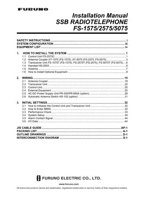
<strong>Installation</strong> <strong>Manual</strong><br />
SSB RADIOTELEPHONE<br />
FS-<strong>15</strong>75/<strong>2575</strong>/<strong>5075</strong><br />
SAFETY INSTRUCTIONS ................................................................................................ i<br />
SYSTEM CONFIGURATION .......................................................................................... iii<br />
EQUIPMENT LIST .......................................................................................................... iv<br />
1. HOW TO INSTALL THE SYSTEM .......................................................................... 1<br />
1.1 Control Unit FS-<strong>2575</strong>C ..................................................................................................1<br />
1.2 Antenna Coupler AT-<strong>15</strong>75 (FS-<strong>15</strong>75), AT-<strong>5075</strong> (FS-<strong>2575</strong>, FS-<strong>5075</strong>)...........................3<br />
1.3 Transceiver Unit FS-<strong>15</strong>75T (FS-<strong>15</strong>75), FS-<strong>2575</strong>T (FS-<strong>2575</strong>), FS-<strong>5075</strong>T (FS-<strong>5075</strong>)....6<br />
1.4 Handset HS-2003..........................................................................................................6<br />
1.5 Antenna .........................................................................................................................7<br />
1.6 How to Install Optional Equipment ................................................................................8<br />
2. WIRING ................................................................................................................... <strong>15</strong><br />
2.1 Antenna Coupler..........................................................................................................18<br />
2.2 Transceiver Unit ..........................................................................................................22<br />
2.3 Control Unit..................................................................................................................25<br />
2.4 External Equipment .....................................................................................................25<br />
2.5 AC-DC Power Supply Unit PR-300/PR-850A (option).................................................28<br />
2.6 Automatic Antenna Switch AS-102 (option) ................................................................31<br />
3. INITIAL SETTINGS................................................................................................. 32<br />
3.1 How to Initialize the Control Unit and Transceiver Unit ...............................................32<br />
3.2 How to Enter MMSI .....................................................................................................32<br />
3.3 Performance Check.....................................................................................................33<br />
3.4 System Setup ..............................................................................................................34<br />
3.5 Alarm Contact Signal...................................................................................................44<br />
3.6 I/O Data .......................................................................................................................44<br />
JIS CABLE GUIDE ....................................................................................................AP-1<br />
PACKING LIST............................................................................................................ A-1<br />
OUTLINE DRAWINGS ................................................................................................ D-1<br />
INTERCONNECTION DIAGRAM ................................................................................ S-1<br />
www.furuno.com<br />
All brand and product names are trademarks, registered trademarks or service marks of their respective holders.
The paper used in this manual<br />
is elemental chlorine free.<br />
・FURUNO Authorized Distributor/Dealer<br />
9-52 Ashihara-cho,<br />
Nishinomiya, 662-8580, JAPAN<br />
All rights reserved. Printed in Japan<br />
Pub. No. IME-56770-<strong>E1</strong><br />
(REFU ) FS-<strong>15</strong>75/<strong>2575</strong>/<strong>5075</strong><br />
A : JUL . 2011<br />
<strong>E1</strong> : JUN . 14, <strong>2012</strong><br />
*00017516914*<br />
*00017516914*<br />
* 0 0 0 1 7 5 1 6 9 1 4 *
SAFETY INSTRUCTIONS<br />
The installer must read the safety instructions before attempting to install the equipment.<br />
DANGER<br />
WARNING<br />
CAUTION<br />
Indicates a potentially hazardous situation which, if not avoided,<br />
will result in death or serious injury.<br />
Indicates a potentially hazardous situation which, if not avoided,<br />
could result in death or serious injury.<br />
Indicates a potentially hazardous situation which, if not avoided,<br />
may result in minor or moderate injury.<br />
Warning, Caution Prohibitive Action Mandatory Action<br />
DANGER<br />
Never touch the SSB antenna,<br />
antenna coupler or lead-in<br />
insulator when the SSB radiotelephone<br />
is transmitting.<br />
High voltage that will cause death<br />
or serious injury is present at the<br />
locations shown in the illustration<br />
below.<br />
Antenna<br />
Coupler<br />
Indoor<br />
Antenna Wire<br />
(High Voltage)<br />
Antenna<br />
Wire<br />
Lead-in<br />
Insulator<br />
(High Voltage)<br />
Do not touch the whip antenna<br />
or wire antenna.<br />
WARNING<br />
Do not work inside the equipment<br />
unless totally familiar with<br />
electrical circuits.<br />
Hazardous voltage which can<br />
shock exists inside the equipment.<br />
Turn off the power at the mains<br />
switchboard before beginning<br />
the installation.<br />
Post a sign near the switchboard<br />
to indicate it should not<br />
be turned on while the equipment<br />
is being installed.<br />
Fire, electrical shock or serious<br />
injury can result if the power is left<br />
on or is applied while the<br />
equipment is being installed.<br />
Electrical shock, serious injury or<br />
death can result if the antenna is<br />
touched during transmission.<br />
i
SAFETY INSTRUCTIONS<br />
CAUTION<br />
Confirm that the power supply<br />
voltage is compatible with the<br />
voltage rating of the equipment.<br />
Connection to the wrong power<br />
supply can cause fire or damage<br />
the equipment.<br />
Ground the equipment.<br />
Ungrounded equipment can give off<br />
or receive electromagnetic<br />
interference or cause electrical<br />
shock.<br />
Handle the copper strap with<br />
care.<br />
The strap has sharp edges that can<br />
cut fingers.<br />
Follow the compass safe distances to prevent<br />
interference to a magnetic compass.<br />
Unit<br />
NOTICE<br />
Standard<br />
Compass<br />
Steering<br />
Compass<br />
FS-<strong>15</strong>75T 2.30 m 1.50 m<br />
FS-<strong>2575</strong>T 2.40 m 1.50 m<br />
FS-<strong>5075</strong>T 2.45 m 1.50 m<br />
FS-<strong>2575</strong>C 0.60 m 0.40 m<br />
HS-2003 1.50 m 0.95 m<br />
AT-<strong>15</strong>75-AES 0.85 m 0.55 m<br />
AT-<strong>15</strong>75-SUS 0.75 m 0.45 m<br />
AT-<strong>5075</strong> 0.80 m 0.50 m<br />
PP-510 1.00 m 0.80 m<br />
IC-350 1.20 m 0.75 m<br />
SEM-21Q 2.20 m 1.50 m<br />
PR-850A 1.00 m 0.70 m<br />
IB-583 0.70 m 0.40 m<br />
IB-585 0.85 m 0.55 m<br />
AS-102 0.65 m 0.40 m<br />
IF-8500 1.05 m 0.70 m<br />
5139U 0.30 m 0.30 m<br />
PR-300 0.90 m 0.70 m<br />
ii
SYSTEM CONFIGURATION<br />
* 3 For DSC routine frequency<br />
watch keeping receiver<br />
AUTOMATIC ANTENNA<br />
* 3 SWITCH AS-102<br />
* 1 * 1 * 4<br />
ANTENNA COUPLER<br />
PREAMP PREAMP ANT. JUNC. BOX AJB1-1A or AT-<strong>15</strong>75 (FS-<strong>15</strong>75) or<br />
FAX-5 FAX-5 MATCHING BOX ARD-1 AT-<strong>5075</strong> (FS-<strong>2575</strong>, FS-<strong>5075</strong>)<br />
* 1 2.6 m whip<br />
antenna<br />
* 4 RX antenna<br />
WR BOARD * 3<br />
EXTERNAL<br />
LOUDSPEAKER<br />
SEM-21Q<br />
BK INTERFACE<br />
BK-300<br />
NAVIGATOR<br />
CONTROL UNIT<br />
FS-<strong>2575</strong>C<br />
HANDSET<br />
HS-2003<br />
ALARM<br />
SYSTEM<br />
EXTERNAL<br />
EQUIPMENT<br />
TRANSCEIVER<br />
UNIT<br />
FS-<strong>15</strong>75T<br />
(FS-<strong>15</strong>75)<br />
or<br />
FS-<strong>2575</strong>T<br />
(FS-<strong>2575</strong>)<br />
or<br />
FS-<strong>5075</strong>T<br />
(FS-<strong>5075</strong>)<br />
For DSC<br />
NBDP TERMINAL UNIT<br />
IB-583 or IB-585<br />
PRINTER<br />
PP-510<br />
PRINTER<br />
INTERFACE<br />
IF-8500* 2<br />
24<br />
VDC<br />
For NBDP<br />
24 VDC * 2 Required for NBDP Terminal<br />
and DSC to share printer.<br />
KEYBOARD<br />
5139U (IB-585)<br />
G84-4100PPAUS (IB-583)<br />
ALARM UNIT<br />
IC-350<br />
No. 2 CONTROL<br />
UNIT FS-<strong>2575</strong>C<br />
EXTERNAL<br />
LOUDSPEAKER<br />
SEM-21Q<br />
HANDSET<br />
HS-2003<br />
AC-DC POWER<br />
SUPPLY UNIT<br />
PR-850A<br />
(for FS-<strong>2575</strong>/<strong>5075</strong>)<br />
or<br />
AC-DC POWER<br />
SUPPLY UNIT<br />
PR-300<br />
(for FS-<strong>15</strong>75)<br />
Unit<br />
Preamp Unit<br />
Antenna Coupler<br />
Other Units<br />
24 VDC<br />
100/110/120/200/220/240 VAC<br />
1ø, 50/60 Hz<br />
Category<br />
Exposed to the weather<br />
Exposed to the weather or<br />
protected from the weather<br />
Protected from the weather<br />
100/110/200/220 VAC<br />
1ø, 50/60 Hz<br />
: STANDARD<br />
: OPTION<br />
: LOCAL SUPPLY<br />
iii
EQUIPMENT LIST<br />
Standard Supply<br />
Name Type Code No. Qty Remarks<br />
Transceiver FS-<strong>15</strong>75T -<br />
For FS-<strong>15</strong>75<br />
Unit<br />
FS-<strong>2575</strong>T - 1 For FS-<strong>2575</strong><br />
FS-<strong>5075</strong>T - For FS-<strong>5075</strong><br />
Control Unit FS-<strong>2575</strong>C - 1<br />
Antenna AT-<strong>15</strong>75 -<br />
For FS-<strong>15</strong>75<br />
Coupler<br />
1<br />
AT-<strong>5075</strong> - For FS-<strong>2575</strong>/<strong>5075</strong><br />
<strong>Installation</strong> CP05-12100 000-019-245<br />
For FS-<strong>2575</strong>C, no cable, with inst. mat.<br />
Materials<br />
CP05-12101<br />
1<br />
CP05-12110 000-019-301 For FS-<strong>2575</strong>C, with DSUB<strong>15</strong>-5P-L5M<br />
cable<br />
CP05-12300 000-019-247<br />
05S0952 *10M* Between transceiver<br />
CP05-12310 000-019-248 05S0952 *20M*<br />
unit & an-<br />
CP05-12320 000-192-490 05S0952 *30M* tenna coupler.<br />
CP05-12330 000-019-250 05S0952 *40M*<br />
CP05-12340 000-019-251 05S0952 *50M*<br />
1<br />
CP05-10800 000-057-435 05S0793 *10M* Between transceiver<br />
CP05-10810 000-057-436 05S0793 *20M*<br />
unit & an-<br />
CP05-10820 000-057-453 05S0793 *30M* tenna coupler.<br />
(w/armor)<br />
CP05-10830 000-057-454 05S0793 *40M*<br />
CP05-10840 000-057-455 05S0793 *50M*<br />
CP05-12400 000-019-216<br />
DSUB<strong>15</strong>-5P-L10M Between transceiver<br />
CP05-12410 000-019-217 DSUB<strong>15</strong>-5P-L20M<br />
unit & con-<br />
CP05-12420 000-019-218 1 DSUB<strong>15</strong>-5P-L30M trol unit.<br />
CP05-12430 000-019-219 DSUB<strong>15</strong>-5P-L40M<br />
CP05-12440 000-019-220 DSUB<strong>15</strong>-5P-L50M<br />
CP05-12001 001-135-560 1 For FS-<strong>15</strong>75T/<strong>2575</strong>T/<strong>5075</strong>T<br />
CP05-12201 001-135-590 1 For AT-<strong>15</strong>75/<strong>5075</strong><br />
CP05-12901 001-175-190 1 For AT-<strong>15</strong>75<br />
Accessories FP05-06600 000-019-246<br />
Handset HS-2003-<strong>15</strong>, FP05-05510,<br />
1<br />
FP05-05511<br />
Spare Parts SP05-06300 000-020-893 1 For FS-<strong>15</strong>75, For HK only<br />
SP05-06000 000-019-214 1 For FS-<strong>2575</strong><br />
SP05-06100 000-019-2<strong>15</strong> 1 For FS-<strong>5075</strong><br />
Optional Equipment<br />
Name Type Code No. Remarks<br />
Printer PP-510 - w/inst. mat. CP16-01200 and<br />
accessories FP16-00100<br />
Control Unit FS-<strong>2575</strong>C - No. 2 Control Unit<br />
Printer Interface IF-8500 000-053-895<br />
External<br />
Loudspeaker<br />
SEM-21Q 001-165-970-10<br />
iv
EQUIPMENT LIST<br />
Name Type Code No. Remarks<br />
Terminal Unit IB-583 000-043-435 For NBDP<br />
IB-585 000-020-894 For NBDP, with bracket<br />
000-021-652 For NBDP, no bracket<br />
Preamp FAX-5 *<strong>15</strong>M* 000-011-702 w/<strong>15</strong> m cable<br />
FAX-5 *1M* 000-011-703 w/1 m cable<br />
AC-DC Power PR-300 000-0<strong>15</strong>-941-10 For FS-<strong>15</strong>75<br />
Supply Unit PR-850A 000-057-233 For FS-<strong>2575</strong>/<strong>5075</strong><br />
Matching Box ARD-1 005-502-230 For matching, w/resistor<br />
Antenna Junction AJB1-1A 000-870-284 For matching, no resistor<br />
Box<br />
Automatic Antenna<br />
AS-102 000-016-464 Automatic antenna switching<br />
Switch<br />
Antenna Switch AS1-1E 000-167-029-10 <strong>Manual</strong> antenna switching<br />
BK Interface BK-300 000-013-305<br />
Flush Mount Kit OP05-122 001-135-600 For Control Unit<br />
Watch Receiver OP05-123 001-135-610<br />
Kit<br />
Connector Set OP05-124 001-135-620 M-P-7, 2 pcs., FMA-1<br />
Full Duplex Kit OP05-125 001-135-630 For FS-<strong>5075</strong><br />
Waterproofing Kit OP05-126 001-148-880 For FS-<strong>2575</strong>C<br />
Key Template OP05-101 004-447-450 For Russian flag vessels (IB-<br />
583)<br />
OP05-135 001-184-560 For Russian flag vessels (IB-<br />
585)<br />
Hose Clamp OP08-11 005-946-960 For Preamp FAX-5<br />
Extension Cable<br />
Kit<br />
OP04-2 *10M* 000-041-174 3D2V assy., w/relay connector<br />
OP04-2 *20M* 000-041-175<br />
OP04-2 *30M* 000-041-176<br />
OP04-2 *40M* 000-041-177<br />
OP04-2 *50M* 000-041-178<br />
Whip Antenna FAW-6R2A 000-107-921 6 m, universal bracket, copper<br />
terminal<br />
FAW-6R2 000-572-108 6 m, no universal bracket, copper<br />
terminal<br />
FAW-6RP2 000-572-109 6 m, universal bracket, M-plug<br />
FAW-6D 000-572-128 6 m, universal bracket, copper<br />
terminal<br />
04S4176 001-073-340-10 2.6 m<br />
WH-027-8M 001-138-110-10 8 m whip antenna<br />
WH-027-8M02 001-138-120-10 8 m whip antenna<br />
WH-027-8M03 001-138-140-10 8 m whip antenna<br />
WH-027-10M 001-139-400-10 10 m whip antenna<br />
<strong>Manual</strong> Tilting<br />
Mechanism<br />
WH-027-KD 001-139-410-10 For WH-027-8M02/10M<br />
WH-027-KD2 001-141-850-10 For WH-027-10M<br />
Accessories FP05-05700 000-010-246 Handset HS-2003-<strong>15</strong>, Bracket<br />
FP-05510, Accessories FP05-<br />
05511<br />
Handset HS-2003-<strong>15</strong> 000-054-223<br />
Bracket for Handset<br />
FP05-05510 005-951-790<br />
v
EQUIPMENT LIST<br />
Name Type Code No. Remarks<br />
Antenna <strong>Installation</strong><br />
CP05-09010 005-954-180 10 m<br />
Materials CP05-09020 005-964-410 25 m<br />
E-22 000-050-632<br />
E-24 000-050-634<br />
E-25 000-050-635<br />
E-26 000-050-636<br />
E-27 000-050-637<br />
Wire Rope Assy. TM-173-D4 L<strong>15</strong>20Y8 000-176-211-10 For FS-<strong>15</strong>75<br />
TM-173-D4 L1670Y8 000-175-179-10 For FS-<strong>2575</strong><br />
TM-173-D4 L1800Y8 000-175-178-10 For FS-<strong>5075</strong><br />
Coaxial Cable RG-10/U-Y 000-<strong>15</strong>9-411-10 10 m<br />
000-<strong>15</strong>9-412-10 20 m<br />
000-<strong>15</strong>9-413-10 30 m<br />
000-<strong>15</strong>9-414-10 40 m<br />
000-<strong>15</strong>9-4<strong>15</strong>-10 50 m<br />
RG-8A/U 000-167-213-10 10 m<br />
000-167-214-10 20 m<br />
000-169-060-10 30 m<br />
000-169-062-10 40 m<br />
000-169-064-10 50 m<br />
Cable Assy. 57FE-17JE-<br />
BC10PL3000<br />
000-174-473-10<br />
Cable Assy<br />
(7-core)<br />
Cable Assy<br />
(5-pair)<br />
05S0952 *10M* 000-758-821-10 Between transceiver unit & antenna<br />
05S0952 *20M* 000-758-822-10<br />
coupler<br />
05S0952 *30M* 000-758-823-10<br />
05S0952 *40M* 000-758-824-10<br />
05S0952 *50M* 000-758-825-10<br />
05S0793 *10M* 000-125-984-10 Between transceiver unit & antenna<br />
05S0793 *20M* 000-125-986-10<br />
coupler<br />
05S0793 *30M* 000-125-987-10 w/armor<br />
05S0793 *40M* 000-125-988-10<br />
05S0793 *50M* 000-125-989-10<br />
Cable Assy. DSUB<strong>15</strong>-5P-L5M 001-146-850-10 Between transceiver unit &<br />
DSUB<strong>15</strong>-5P-L10M 001-146-860-10 control unit<br />
DSUB<strong>15</strong>-5P-L20M 001-146-870-10<br />
DSUB<strong>15</strong>-5P-L30M 001-146-880-10<br />
DSUB<strong>15</strong>-5P-L40M 001-146-890-10<br />
DSUB<strong>15</strong>-5P-L50M 001-146-900-10<br />
vi
1. HOW TO INSTALL THE SYSTEM<br />
1.1 Control Unit FS-<strong>2575</strong>C<br />
1.1.1 <strong>Installation</strong> location<br />
• The location must not be near water, rain and water splash.<br />
• Make sure the location is strong enough to hold the unit under the conditions of continued<br />
vibration and shock normally found on the boat.<br />
• Install the unit where the controls can easily be operated.<br />
• Install the unit where it does not cause the interference to persons or prevent operation of other<br />
equipment, especially the ship’s wheel.<br />
• Follow the compass safe distances shown in the Safety Instructions to prevent the interference<br />
to a magnetic compass.<br />
• Follow the recommended maintenance space shown in the outline drawing to allow the serviceman<br />
to reach the connectors at the rear of the unit.<br />
• Direct sunlight can cause the inside of the unit to become hot. Install the unit away from direct<br />
sunlight.<br />
1.1.2 How to install the unit on a desktop<br />
A bracket is provided to install the unit on a desktop.<br />
1. Fasten the bracket to the installation location with the self-tapping screws.<br />
2. Loosely screw in the knobs at the sides of unit.<br />
3. Set the unit to the bracket and tighten the knobs.<br />
Knob<br />
Knob<br />
Bracket<br />
1
1. HOW TO INSTALL THE SYSTEM<br />
1.1.3 How to install the unit in a console (flush mount)<br />
The flush mount kit is required to install the Control Unit in a console.<br />
Type: OP05-122, Code No.: 001-135-600<br />
Name Type Code No. Qty<br />
Mounting metal 05-089-1171-0 100-299-020 2<br />
Wing bolt M4×40 YBSC2 000-175-263-10 4<br />
Wing nut M4 YBSC2 000-168-239-10 4<br />
Hex. bolt M6×12 SUS304 000-162-897-10 2<br />
Spring washer M6 SUS304 000-<strong>15</strong>8-855-10 2<br />
Protector for screw 26-005-2125-0 100-354-800-10 4<br />
1. Make a cutout in the installation location. See the outline drawing.<br />
2. Set the Control Unit to the cutout.<br />
3. Attach two mounting metals (supplied) to the Control Unit with two hex bolts (M6×12, supplied)<br />
and M6 spring washers (supplied).<br />
Mounting metal<br />
4. Screw the wing bolts and the wing nuts to the mounting metal, then attach the protectors for<br />
screws as below.<br />
Wing nut<br />
Wing bolt<br />
Mounting metal<br />
Protector for<br />
screw<br />
5. Fasten each wing bolt so that the protector for screw touches the back side of the mounting<br />
place.<br />
Protector for<br />
screw<br />
6. Fasten the wing nuts tightly.<br />
2
1. HOW TO INSTALL THE SYSTEM<br />
1.2 Antenna Coupler AT-<strong>15</strong>75 (FS-<strong>15</strong>75), AT-<strong>5075</strong><br />
(FS-<strong>2575</strong>, FS-<strong>5075</strong>)<br />
The Antenna Coupler is installed between the antenna and the Transceiver Unit, and tunes the<br />
antenna to the transmitter. The coupler must have a correct ground to function properly. The radiotelephone<br />
cannot provide its intended performance unless the ground is proper.<br />
DANGER<br />
ELECTRICAL SHOCK HAZARD<br />
Do not touch lead-in wire or<br />
insulator. Electric shock, fire,<br />
serious injury or death can<br />
result if the cables or insulator<br />
are touched while the<br />
radiotelephone is transmitting.<br />
Do not touch.<br />
Pictured: AT-<strong>5075</strong><br />
1.2.1 <strong>Installation</strong> location<br />
The water-jetsproof construction of the antenna coupler permits installation either indoors or outdoors.<br />
Install the unit on a bulkhead or the overhead (indoor installation). Do not install the unit on<br />
a deck.<br />
When selecting a location, keep in mind the following points.<br />
General considerations<br />
• Select a location where the coupler can be easily maintained, but where it will not interfere with<br />
crew or passengers.<br />
• Follow the compass safe distances listed in the Safety Instructions to prevent interference to a<br />
magnetic compass.<br />
• Leave enough space around the sides of the coupler for maintenance and checking. See the<br />
outline drawing for minimum space.<br />
• Install the coupler close to the antenna base and as near to the ground as possible, for optimum<br />
radio energy.<br />
• The lead-in wire should be as near to the coupler as possible.<br />
Indoor installation<br />
• Install the unit away from GNNS equipment, radio equipment, etc. to prevent mutual interference.<br />
3
1. HOW TO INSTALL THE SYSTEM<br />
Outdoor installation<br />
• The coupler is water-jetsproof, but is not designed to take a continual soaking. If necessary,<br />
cover the top and sides with a wooden housing (or similar enclosure) or by sealing any opening<br />
in the top or sides with silicone sealant.<br />
• Keep wires as short as possible and keep the wires away from any grounded conductors such<br />
as lifelines, mast shrouds, or fittings.<br />
• Locate the insulator away from funnels, etc.<br />
1.2.2 Ground<br />
CAUTION<br />
Ground the equipment.<br />
Ungrounded equipment can<br />
give off or receive electromagnetic<br />
interference or<br />
cause electrical shock.<br />
The ground connection must have the lowest possible RF-impedance. Losses in the ground connection<br />
reduce the communication distance.<br />
Make the ground connection to the Antenna Coupler with a copper strap, constructed as shown<br />
below. For vessels with conducting hulls, make the width at least 60 mm and the length not<br />
more than one meter. For FRP vessels, make the width at least 60 mm and the length not more<br />
than five meters.<br />
Connect to the ground termnaml of the<br />
antenna coupler.<br />
Copper strap<br />
Ground plate<br />
(a piece of steel plate)<br />
Solder<br />
For outdoor installation, apply a coat<br />
of marine paint to prevent corrosion.<br />
For outdoor installation, do the following.<br />
Braze<br />
Weld to ship's structure<br />
• Coat the junction where the copper strap connects to the ground terminal of the antenna coupler<br />
with silicone sealant.<br />
• Coat the copper strap between the ground plate and ground terminal of the anntenna coupler<br />
with marine paint to prevent corrosion.<br />
• Add a supplemental ground wire (local supply, more than 14 sq) and fasten it to the ground terminal<br />
of the antenna coupler as shown below.<br />
Ground terminal of the antenna coupler.<br />
Copper strap<br />
Fasten the supplemental<br />
ground wire (more than<br />
14 sq).<br />
4
1. HOW TO INSTALL THE SYSTEM<br />
1.2.3 <strong>Installation</strong> procedure<br />
Outdoor installation<br />
Fasten the Antenna Coupler to a bulkhead of the bridge, mast, handrail, etc., with the M6 bolts<br />
(local supply).<br />
For installation on the mast, see section 1.5 to select a location. Weld suitable mounting fixtures<br />
(local supply) to the mast and bolt the coupler there.<br />
Fix with four<br />
M6 bolts<br />
(local supply).<br />
Mounting fixture<br />
(Local supply)<br />
Indoor installation<br />
Pictured: AT-<strong>5075</strong><br />
DO NOT install<br />
coupler horizontally.<br />
Fasten the Antenna Coupler to a bulkhead on the bridge or the overhead. Select a location where<br />
the distance between the lead-in insulator and the coupler is as short as possible.<br />
Lead-in<br />
insulator<br />
Antenna switch<br />
<strong>Installation</strong> on the overhead<br />
Stand-off<br />
insulator<br />
From antenna selection switch<br />
<strong>Installation</strong> on a bulkhead<br />
5
1. HOW TO INSTALL THE SYSTEM<br />
1.3 Transceiver Unit FS-<strong>15</strong>75T (FS-<strong>15</strong>75),<br />
FS-<strong>2575</strong>T (FS-<strong>2575</strong>), FS-<strong>5075</strong>T (FS-<strong>5075</strong>)<br />
Select a location that meets these conditions:<br />
• Install only on a bulkhead.<br />
• Select a location which provides good ventilation.<br />
• The location must be clean and dry.<br />
• Make sure the location can hold the unit under the conditions of continued vibration and shock<br />
normally found on the boat. If necessary, increase the strength the installation location.<br />
• Follow the compass safety distance shown in the Safety Instructions to prevent the interference<br />
to a magnetic compass.<br />
• Follow the recommended service space shown in the outline drawing to provide space for maintenance<br />
and checking.<br />
• Install the unit away from direct sunlight to prevent overheating.<br />
Fasten the unit with 6×30 self-tapping screws. Refer to the outline drawing for installation dimensions.<br />
1.4 Handset HS-2003<br />
Unfasten six screws to remove the bracket cover. Fasten the bracket to the location with two selftapping<br />
screws 4x16 (supplied).<br />
65<br />
77<br />
57<br />
Handset<br />
bracket cover<br />
Screws<br />
208<br />
φ12 Cable entrance<br />
22<br />
42<br />
2-φ4.5<br />
Fixing hole<br />
6
1. HOW TO INSTALL THE SYSTEM<br />
1.5 Antenna<br />
The antenna plays the most important role in radio communication. If it cannot receive or transmit<br />
due to improper installation, even the most sophisticated transceiver will be useless.<br />
Types of antennas<br />
The most commonly used antenna is a<br />
whip antenna. The recommended minimum<br />
total length is 10 meters. For an 8 m<br />
whip antenna, secure it with a lead-in wire<br />
of at least 2 m in length, as shown in the illustration<br />
at right.<br />
A long wire antenna can also be used. The<br />
total length must be between 10 and 18<br />
meters.<br />
After setting up the equipment, confirm<br />
that the antenna can tune all frequencies.<br />
General requirements<br />
At least<br />
1 m<br />
8 m or<br />
more<br />
2 m or more<br />
(when using an 8 m<br />
whip antenna)<br />
<br />
Pedestal<br />
As vertically as possible and not less than<br />
45 degrees towards the horizontal plane.<br />
Antenna Switch<br />
(option)<br />
Antenna<br />
Coupler<br />
• Separate the TX antenna as far as possible from stays, metallic objects, and direction finder<br />
antenna.<br />
• The distance to an Inmarsat antenna must be more than five meters.<br />
• The RX antenna (required for duplex communications) should be separated at least five meters<br />
from the TX antenna. Install a receiving antenna junction box at the base of the antenna.<br />
• Locate the insulator away from funnels, etc.<br />
• Use a wave-type insulator to connect to the coupler (or antenna switch) and leave some slack<br />
in the feed-in wire, to prevent direct stress to the coupler.<br />
<strong>Installation</strong> requirements for whip antenna<br />
• The installation arrangement of the antenna or pedestal must be constructed to withstand the<br />
strain from swaying and vibration.<br />
• Locate the antenna in an elevated position on the ship and at least one meter away from conductive<br />
structures.<br />
• Insulate the down lead from the base of the antenna to the coupler. Run as vertically as possible<br />
and not less than 45 degrees towards the horizontal plane.<br />
• For indoor installation, use a lead-in insulator (FURUNO type: YA-256) to make the connection.<br />
If necessary, use a high quality antenna switch and stand-off insulator.<br />
• it is recommended to construct an enclosure around the whip antenna to prevent contact with<br />
the antenna. Also, post a weather resistant “DANGER HIGH VOLTAGE” sign on the enclosure.<br />
<strong>Installation</strong> requirements for a long wire antenna<br />
• The length of the vertical portion should be longer than four meters. Run as vertically as possible<br />
and within 10 degrees toward the vertical plane.<br />
RX antenna<br />
An RX antenna is required for duplex communications.<br />
7
1.6 How to Install Optional Equipment<br />
1.6.1 Preamp Unit FAX-5<br />
1. HOW TO INSTALL THE SYSTEM<br />
The preamp unit can be mounted two ways: screwed on to a mast or fixed to a mast, using stainless<br />
steel hose clamps (optional supply). The mast should not be longer than 1.5 m (5 feet) to prevent<br />
undue flexing in heavy winds.<br />
For detailed installation procedure, see the outline drawing for the preamp unit.<br />
1.6.2 Printer PP-510<br />
Refer to the outline drawing at the end of this manual for mounting dimensions and recommended<br />
maintenance space. Follow the compass safety distance shown in the Safety Instructions to prevent<br />
interference to a magnetic compass. Connect the interconnection cable between the printer<br />
and the Control Unit (or Printer Interface). For how to load paper and set ribbon cassette, refer to<br />
the Operator’s <strong>Manual</strong> of the printer.<br />
Fix the printer to the mounting location with the two mounting fixtures provided.<br />
Mounting Fixture (1)<br />
Mounting Fixture (2)<br />
1.6.3 Printer Interface IF-8500<br />
Refer to the outline drawing at the end of this manual for mounting dimensions and recommended<br />
maintenance space. Follow the compass safety distance shown in the Safety Instructions to prevent<br />
interference to a magnetic compass. Fasten the Printer Interface with self-tapping screws (local<br />
supply) to desktop or bulkhead.<br />
1.6.4 External Loudspeaker SEM-21Q<br />
The external loudspeaker can be installed on a tabletop, the overhead or bulkhead. Follow the<br />
compass safety distance shown in the Safety Instructions to prevent interference to a magnetic<br />
compass. See the outline drawing at the back of this manual for mounting dimensions and recommended<br />
maintenance space. Select a location that is within 2.8 m of the Control Unit because that<br />
is the length of the connection cable. Fasten the loudspeaker to the mounting location with the<br />
self-tapping screws (supplied).<br />
8
1. HOW TO INSTALL THE SYSTEM<br />
1.6.5 AC-DC Power Supply PR-850A, PR-300<br />
Select a location that satisfies the following conditions:<br />
• The location provides good ventilation.<br />
• The location is clean and dry.<br />
• Make sure the location is strong enough to support the unit under the conditions of continued<br />
vibration and shock normally encountered on the boat.<br />
• Follow the compass safety distance in the Safety Instructions to prevent interference to a magnetic<br />
compass.<br />
• The location provides the maintenance space shown in the outline drawing.<br />
1.6.6 Terminal Unit IB-583, IB-585<br />
Install the Terminal Unit on a desktop. Select a location that meets the following conditions.<br />
• The temperature and humidity in the location must be stable and moderate.<br />
• Keep the unit away from the high-power radiotelephone and its feeder wire so that RFI (Radio<br />
Frequency Interference) is minimum.<br />
• Follow the compass safety distance shown in the Safety Instructions to prevent the interference<br />
to a magnetic compass.<br />
• Follow the recommended maintenance space shown in the outline drawing to facilitate maintenance<br />
and checking.<br />
How to install the terminal unit<br />
1. Fix the bracket to the location with four self-tapping screws (supplied).<br />
2. Loosely screw in two knobs in the terminal unit.<br />
3. Set the terminal unit to the bracket and tighten the knobs.<br />
How to install the keyboard<br />
1. Attach the function key label to the keyboard as shown below.<br />
Function key label (supplied)<br />
Esc F1 F2 F3 F4 F5 F6 F7 F8 F9 F10 Num<br />
Lock<br />
F11 F12<br />
Prt Sc<br />
Sys Rq<br />
Scroll<br />
Lock<br />
Pause<br />
Break<br />
!<br />
1<br />
@<br />
2<br />
#<br />
3<br />
$<br />
4<br />
%<br />
5<br />
^ &<br />
( )<br />
6 7 7 8 8 9 9 0 -<br />
+<br />
=<br />
Backspace<br />
Home<br />
Tab<br />
Caps<br />
Lock<br />
Shift<br />
Ctrl<br />
Ctrl<br />
Q W E R T Y U I O P { }<br />
4 5 5 6 - [ ] \<br />
A S D F G H J K L : "<br />
; + '<br />
1 2 3<br />
Z X C V B N M < > ?<br />
, . / /<br />
0 Shift<br />
Alt Alt Ins Del<br />
Fn<br />
Enter<br />
Enter<br />
Pg Up<br />
Pg Dn<br />
End<br />
Keyboard for IB-583<br />
Keyboard for IB-585<br />
2. Attach four fasteners (small, supplied with the optional kit) to the bottom of the keyboard.<br />
3. Attach four fasteners (large, supplied with the optional kit) to the small fasteners used in step<br />
2.<br />
4. Remove the paper from four fasteners.<br />
5. Fasten the keyboard to the location.<br />
9
1. HOW TO INSTALL THE SYSTEM<br />
1.6.7 Automatic Antenna<br />
Switch AS-102<br />
The AS-102 allows you to connect the antenna<br />
to ground remotely when there is a<br />
possibility of lightning, or the antenna must<br />
be grounded to meet with local regulations<br />
when returning to a harbor. Install the switch<br />
between the antenna and the Antenna Coupler.<br />
Fasten the unit on a bulkhead with four<br />
5×20 self-tapping screws (supplied), or bolts<br />
and nuts. Coat the ground terminal with silicone<br />
sealant. An external switch can be installed<br />
to turn off the antenna manually. See<br />
the interconnection diagram.<br />
Fixing hole (4 pcs.)<br />
Fasten unit with four<br />
self-tapping screws<br />
(5x20, supplied).<br />
1.6.8 WR2 Board<br />
The WR2 Board (05P0847B) enables reception of DSC routine frequencies while using the SSB<br />
radiotelephone connection. A whip antenna (to WR2_ANT) is necessary.<br />
Parts name: Watch Receiver Kit, Type: OP05-123, Code No. 001-135-610<br />
Name Type Code No. Qty<br />
WR2 Board 05P0847B(LF) 001-137-100 1<br />
Binding head screw M3×6 SUS304 000-163-485-10 6<br />
Mini-pin assy. L-200 07S0046 000-165-847-10 1<br />
Connector assy. MJ145-TMP-1.5D-L520 000-175-320-10 1<br />
Shield case 03-161-1011-0 100-302-730-10 2<br />
1. The Preamp Unit FAX-5 requires 12 VDC power. Set the jumper block J3 on the WR2 Board<br />
to the ACTIVE position to supply power to the unit.<br />
Jumper block J3<br />
ACTIVE<br />
2. Open both the Transceiver Unit and the shield cover.<br />
10
1. HOW TO INSTALL THE SYSTEM<br />
3. Fasten the WR2 Board with four screws (supplied) at the location shown below.<br />
Fasten WR2<br />
Board here.<br />
4. Make the following connections between the WR2 Board / ANT WR2 / RX-FIL Board, with the<br />
Mini-pin assy. (supplied with this kit) and the connector assy. (supplied with this kit).<br />
Connections if Divider is connected Connections if Divider is not connected<br />
WR2<br />
Board<br />
TX<br />
Board<br />
WR2<br />
Board<br />
TX<br />
Board<br />
J2 J4<br />
J1 J3 J6<br />
J2<br />
J4<br />
J3<br />
J2 J5 J4<br />
J3<br />
RX-FIL<br />
Board<br />
ANT WR2<br />
• Connect J2 on WR2 Board to J6 on RX-FIL<br />
Board. Use mini-pin assy. L-380.<br />
• Connect J4 on WR2 Board to J3 on TX Board.<br />
Use mini-pin assy. L-200.<br />
• Connect J5 on RX-FIL Board to J4 on RX-FIL<br />
Board. Use existing mini-pin assy.<br />
• Connect J2 on WR2 Board to ANT WR2. Use<br />
connector assy.<br />
• Connect J4 on WR2 Board to J3 on TX Board.<br />
Use mini-pin assy. L-200.<br />
5. For FS-<strong>2575</strong>/<strong>5075</strong>, if a divider is not connected, fasten the connector assy. with the locking<br />
saddle next to the WR2 Board.<br />
6. Close the shield cover and the Transceiver Unit.<br />
7. If a divider is connected, open the [RT SETUP] menu (see section 3.3.4), select [SETUP]<br />
and set [DIVIDER] to [ON].<br />
11
1.6.9 DUP-FIL Board (FS-<strong>5075</strong> only)<br />
1. HOW TO INSTALL THE SYSTEM<br />
The DUP-FIL Board (05P0863) installs above the RX-FIL Board (05P0862) and gives the FS-<strong>5075</strong><br />
full duplex capability. Parts Name: Full Duplex Kit, Type No. OP05-125, Code No. 001-135-630<br />
Name Type Code No. Qty<br />
DUP-FIL Board 05P0863(LF) 001-137-900 1<br />
Mini-pin assy. L-80 000-165-835-10 3<br />
Spacer SQ-<strong>15</strong> 000-<strong>15</strong>9-299-10 4<br />
1. Open both the Transceiver Unit and the shield cover.<br />
2. Make the connections shown below between the DUP-FIL Board and the RX-FIL Board, using<br />
the mini-pin assemblies (supplied).<br />
DUP-FIL RX-FIL<br />
Board Board<br />
J1 J3<br />
J2 J4<br />
J3 J8<br />
3. Unfasten the four pcb mounting screws from the RX-FIL Board. See the illustration below for<br />
the location of the Board.<br />
RX-FIL<br />
Board<br />
4. Screw in four spacers (supplied) in the pcb mounting screw holes for the RX-FIL Board.<br />
5. Set the DUP-FIL Board on top of the spacers then fasten the Board to the spacers with the<br />
screws removed at step 3.<br />
6. Close the shield cover and the Transceiver Unit.<br />
12
1. HOW TO INSTALL THE SYSTEM<br />
1.6.10 Waterproofing kit for the Control Unit<br />
The waterproofing kit OP-126 (Code No. 001-148-880) protects the connectors and jacks on the<br />
control unit from water ingress, to waterproofing standard IP22.<br />
Name Type Code No. Qty<br />
DSUB gasket 05-106-5571-1 100-365-871-10 1<br />
SPJACK gasket 05-106-5572-0 100-365-880-10 1<br />
DSUB clamping plate 05-106-5604-1 100-365-931-10 3<br />
SPJACK clamping plate 05-106-5606-0 100-365-950-10 1<br />
DSUB boot 05-106-5603-0 100-365-920-10 3<br />
SPJACK boot 05-106-5605-0 100-365-940-10 1<br />
Cable tie CV-125N 000-172-164-10 4<br />
Binding head screw M3×8 SUS304 000-162-665-10 8<br />
How to protect unused connector(s), speaker jack<br />
UNUSED CONNECTOR(S)<br />
Two connectors<br />
1) Put the DSUB<br />
gasket on the<br />
unused connectors<br />
and align its<br />
holes with the<br />
screw holes on<br />
the connectors.<br />
Leave the plastic<br />
caps on the connectors.<br />
2) Put the DSUB<br />
clamping plates<br />
on the DSUB<br />
gasket and fasten<br />
them with<br />
four binding<br />
head screws<br />
(torque: 0.5Nm).<br />
Align hole with<br />
screw hole.<br />
DSUB<br />
gasket<br />
DSUB clamping plate<br />
Binding head screw<br />
UNUSED SPEAKER JACK<br />
1) Put the SPJACK gasket on the speaker jack<br />
location. Be sure the gasket seats in the recess.<br />
One connector<br />
1) Cut the DSUB<br />
gasket at the two<br />
places shown, in the<br />
direction of the slit on<br />
the gasket.<br />
2) Put the DSUB<br />
gasket and<br />
DSUB clamping<br />
plate on the unused<br />
connector.<br />
Fasten them with<br />
two binding head<br />
screws (torque:<br />
0.5Nm).<br />
Cut here.<br />
DSUB clamping plate<br />
DSUB gasket<br />
Binding<br />
head<br />
screw<br />
SPJACK<br />
gasket<br />
2) Put the SPJACK clamping plate on the SP-<br />
JACK gasket, with the straight edge on the plate<br />
down. Fasten the plate with two binding head<br />
screws (torque: 0.5Nm).<br />
SPJACK<br />
clamping<br />
plate<br />
13
1. HOW TO INSTALL THE SYSTEM<br />
How to protect connector, speaker jack in use<br />
CONNECTOR IN USE<br />
1) Pass the cable through<br />
the DSUB clamping<br />
plate.<br />
2) Connect the cable to<br />
the control unit. Put the<br />
DSUB boot on the cable,<br />
with the slit on the boot<br />
down.<br />
3) Slide the DSUB boot<br />
downward until it contacts<br />
the control unit.<br />
DSUB<br />
boot<br />
DSUB<br />
clamping<br />
plate<br />
SPEAKER JACK IN USE<br />
1) Pass the cable through<br />
the SPJACK clamping plate.<br />
Note the orientation of the<br />
straight edge on the clamping<br />
plate.<br />
2) Connect the<br />
cable to the<br />
speaker jack. Put<br />
the SPJACK boot<br />
on the cable, with<br />
the slit on the<br />
boot down.<br />
SPJACK<br />
clamping<br />
plate<br />
SPJACK<br />
boot<br />
4) Slide the clamping<br />
plate downward until it<br />
contacts the boot. Be<br />
sure there is no gap between<br />
the plate and the<br />
boot.<br />
Clamping<br />
plate<br />
3) Slide the<br />
clamping plate<br />
downward until it<br />
contacts the boot,<br />
with the straight<br />
edge on the plate<br />
down. Be sure<br />
there is no gap<br />
between the plate<br />
and the boot.<br />
4) Fasten the<br />
plate with two<br />
binding head<br />
screws (torque:<br />
0.5Nm).<br />
Clamping plate<br />
5) Fasten the plate with<br />
two binding head screws.<br />
(torque: 0.5Nm). Fasten<br />
the boot to the cable with<br />
a cable tie.<br />
5) Fasten the boot<br />
to the cable with a<br />
cable tie.<br />
Cable<br />
tie<br />
Cable<br />
tie<br />
14
Esc F1 F2 F3 F4 F5 F6 F7 F8 F9 F10 Num<br />
Lock<br />
F11 F12<br />
! @ # $ % ^ &<br />
( )<br />
+<br />
1 2 3 4 5 6 7 7 8 8 9 9 0 - =<br />
Q W E R T Y U I O P {<br />
Tab<br />
4 5 5 6 - [<br />
Caps A S D F G H J K L : "<br />
Lock<br />
1 2 3 ; + '<br />
Z X C V B N M < > ?<br />
Shift<br />
0 , . / / Shift<br />
Ctrl<br />
Alt Alt Ins Del<br />
Ctrl Fn<br />
Prt Sc Scroll<br />
Lock<br />
Sys Rq<br />
Backspace<br />
}<br />
Pg Up<br />
] \<br />
Pg Dn<br />
Pause<br />
Break<br />
Home<br />
Enter<br />
Enter<br />
End<br />
2. WIRING<br />
The illustration on this page and the next two pages show general connections between the Antenna<br />
Coupler, Transceiver Unit, Control Unit and external equipment. For detailed information,<br />
see the interconnection diagram. Many of the cables mentioned are JIS (Japan Industry Standard)<br />
cables. If not available locally, use the equivalent. See the cable guide in the Appendix for how to<br />
select equivalent cables.<br />
FS-<strong>15</strong>75<br />
TX/RX ANTENNA<br />
or TX ANTENNA<br />
AUTOMATIC ANTENNA<br />
SWITCH AS-102<br />
ANTENNA COUPLER<br />
AT-<strong>15</strong>75<br />
3D-2V<br />
RG-10/U-Y<br />
G84-4100PPAUS<br />
(IB-583)<br />
5139U<br />
(IB-585)<br />
PREAMP<br />
FAX-5<br />
MATCHING BOX ARD-1 or<br />
ANT. JUNC. BOX AJB1-1A<br />
NBDP TERMINAL<br />
IB-583 or IB-585<br />
05S9351<br />
or PRINTER<br />
DSUB<strong>15</strong>-5P-LxxM<br />
RX ANTENNA<br />
PRINTER<br />
INTERFACE IF-8500<br />
CONTROL UNIT<br />
FS-<strong>2575</strong>C<br />
Ground<br />
Wire<br />
TRANSCEIVER UNIT<br />
FS-<strong>15</strong>75T<br />
TTYCS-4*/<br />
TTYCSLA-4*<br />
LOUDSPEAKER<br />
HANDSET<br />
HS-2003<br />
To TB3<br />
Copper strap<br />
(Connect<br />
to ground.)<br />
To TB1<br />
RG-10/U-Y<br />
05S0952 or 05S0793<br />
DPYC-1.5* (or DPYCY-1.5*)<br />
* JIS cable. See Appendix<br />
for equivalent cable.<br />
To WR1 ANT<br />
To R ANT<br />
To T/R ANT<br />
To TB6<br />
To TB7<br />
DPYC-6*<br />
ALARM UNIT<br />
IC-350<br />
TTYCS-1*/<br />
TTYCSLA-1*<br />
24 VDC<br />
Ground<br />
Wire<br />
AC-DC POWER<br />
SUPPLY UNIT<br />
PR-300<br />
GPS NAVIGATOR<br />
(Ex. GP-<strong>15</strong>0)<br />
DPYC-6* 100/110/200/<br />
220/ VAC<br />
DPYC-16*<br />
24 VDC<br />
<strong>15</strong>
Esc F1 F2 F3 F4 F5 F6 F7 F8 F9 F10 Num Prt Sc Scroll Pause<br />
Lock<br />
Lock<br />
F11 F12<br />
Sys Rq<br />
Break<br />
! @ # $ % ^ &<br />
( )<br />
+<br />
Home<br />
Backspace<br />
1 2 3 4 5 6 7 7 8 8 9 9 0 - =<br />
Q W E R T Y U I O P { }<br />
Pg Up<br />
Tab<br />
4 5 5 6 - [ ] \<br />
Caps A S D F G H J K L : "<br />
Pg Dn<br />
Lock<br />
Enter<br />
1 2 3 ; +<br />
Enter<br />
'<br />
Z X C V B N M < > ?<br />
End<br />
Shift<br />
0 , . / / Shift<br />
Ctrl<br />
Alt Alt Ins Del<br />
Ctrl Fn<br />
2. WIRING<br />
FS-<strong>2575</strong><br />
TX/RX ANTENNA<br />
or TX ANTENNA<br />
AUTOMATIC ANTENNA<br />
SWITCH AS-102<br />
ANTENNA COUPLER<br />
AT-<strong>5075</strong><br />
3D-2V<br />
RG-10/U-Y<br />
G84-4100PPAUS<br />
(IB-583)<br />
5139U<br />
(IB-585)<br />
TRANSCEIVER UNIT<br />
FS-<strong>2575</strong>T<br />
NBDP TERMINAL<br />
IB-583 or IB-585<br />
DSUB<strong>15</strong>-5P-LxxM<br />
PREAMP<br />
FAX-5<br />
MATCHING BOX ARD-1 or<br />
ANT. JUNC. BOX AJB1-1A<br />
05S9351<br />
RX ANTENNA<br />
PRINTER<br />
INTERFACE IF-8500<br />
or PRINTER<br />
CONTROL UNIT<br />
FS-<strong>2575</strong>C<br />
Ground<br />
Wire<br />
To TB1<br />
To TB3<br />
Copper strap<br />
(Connect<br />
to ground.)<br />
05S0952 or 05S0793<br />
RG-10/U-Y<br />
DPYC-1.5* (or DPYCY-1.5*)<br />
* JIS cable. See Appendix<br />
for equivalent cable.<br />
To WR1 ANT<br />
To R ANT<br />
To TB6<br />
To T/R ANT<br />
To TB7<br />
DPYC-10*<br />
TTYCS-4*/<br />
TTYCSLA-4*<br />
ALARM UNIT<br />
IC-350<br />
TTYCS-1*/<br />
TTYCSLA-1*<br />
24 VDC<br />
Ground<br />
Wire<br />
AC-DC POWER<br />
SUPPLY UNIT<br />
PR-850A<br />
GPS NAVIGATOR<br />
(Ex. GP-<strong>15</strong>0)<br />
DPYC-6* 100/110/120/200/<br />
220/240 VAC<br />
DPYC-16*<br />
LOUDSPEAKER<br />
HANDSET<br />
HS-2003<br />
24 VDC<br />
16
Esc F1 F2 F3 F4 F5 F6 F7 F8 F9 F10 Num Prt Sc Scroll Pause<br />
Lock<br />
Lock<br />
F11 F12<br />
Sys Rq<br />
Break<br />
! @ # $ % ^ &<br />
( )<br />
+<br />
Home<br />
Backspace<br />
1 2 3 4 5 6 7 7 8 8 9 9 0 - =<br />
Q W E R T Y U I O P { }<br />
Pg Up<br />
Tab<br />
4 5 5 6 - [ ] \<br />
Caps A S D F G H J K L : "<br />
Pg Dn<br />
Lock<br />
Enter<br />
1 2 3 ; +<br />
Enter<br />
'<br />
Z X C V B N M < > ?<br />
End<br />
Shift<br />
0 , . / / Shift<br />
Ctrl<br />
Alt Alt Ins Del<br />
Ctrl Fn<br />
2. WIRING<br />
FS-<strong>5075</strong><br />
TX/RX ANTENNA<br />
or TX ANTENNA<br />
AUTOMATIC ANTENNA<br />
SWITCH AS-102<br />
ANTENNA COUPLER<br />
AT-<strong>5075</strong><br />
3D-2V<br />
RG-10/U-Y<br />
G84-4100PPAUS<br />
(IB-583)<br />
5139U<br />
(IB-585)<br />
TRANSCEIVER UNIT<br />
FS-<strong>5075</strong>T<br />
NBDP TERMINAL<br />
IB-583 or IB-585<br />
DSUB<strong>15</strong>-5P-LxxM<br />
PREAMP<br />
FAX-5<br />
MATCHING BOX ARD-1 or<br />
ANT. JUNC. BOX AJB1-1A<br />
05S9351<br />
RX ANTENNA<br />
PRINTER<br />
I/F KIT IF-8500<br />
or PRINTER<br />
CONTROL UNIT<br />
FS-<strong>2575</strong>C<br />
Ground<br />
Wire<br />
To TB1<br />
To TB3<br />
Copper strap<br />
(Connect<br />
to ground.)<br />
05S0952 or 05S0793<br />
RG-10/U-Y<br />
DPYC-1.5* (or DPYCY-1.5*)<br />
* JIS cable. See Appendix<br />
for equivalent cable.<br />
To WR1 ANT<br />
To R ANT<br />
To TB6<br />
To T/R ANT<br />
To TB7<br />
DPYC-16*<br />
TTYCS-4*/<br />
TTYCSLA-4*<br />
ALARM UNIT<br />
IC-350<br />
TTYCS-1*/<br />
TTYCSLA-1*<br />
24 VDC<br />
Ground<br />
Wire<br />
AC-DC POWER<br />
SUPPLY UNIT<br />
PR-850A<br />
GPS NAVIGATOR<br />
(Ex. GP-<strong>15</strong>0)<br />
DPYC-6* 100/110/120/200/<br />
220/240 VAC<br />
DPYC-16*<br />
LOUDSPEAKER<br />
HANDSET<br />
HS-2003<br />
24 VDC<br />
17
2.1 Antenna Coupler<br />
Note: The T/R antenna is automatically connected to ground when the power is turned off.<br />
2.1.1 General connections<br />
2. WIRING<br />
Three cables connect to the Antenna Coupler: the signal cable (7-core cable (05S0952) or 5P cable<br />
(05S0793)), coaxial cable from the Transceiver Unit, and the antenna wire. For the connection<br />
of the antenna wire, use an insulator so as not to put stress on the connector at the insulator of<br />
the Antenna Coupler. For cable 05S0952, cut off the armor at the outside of the Antenna Coupler,<br />
and then wrap vinyl tape around the end of armor.<br />
1. Open the cover of the Antenna Coupler.<br />
2. Unscrew the nut for the signal cable and coaxial cable and remove the following from each<br />
cable:<br />
AT-<strong>15</strong>75: Gasket<br />
AT-<strong>5075</strong>: Two washers and gasket<br />
3. Do one of the following:<br />
AT-<strong>15</strong>75: Pass the nut and gasket onto the cable as shown below.<br />
AT-<strong>5075</strong>: Pass the nut, two washers and gasket onto the cable in the order shown below.<br />
Washer<br />
Gasket*<br />
Gasket<br />
Washer<br />
Nut<br />
Nut<br />
Nut<br />
* Replace this gasket with one supplied with accessories if<br />
diameter of coax cable is larger than the one supplied.<br />
Antenna Coupler AT-<strong>5075</strong><br />
Antenna Coupler AT-<strong>15</strong>75<br />
Antenna Coupler AT-<strong>15</strong>75, AT-<strong>5075</strong>, bottom front view<br />
18
2. WIRING<br />
4. Connect the signal cable and the coaxial cable as shown below.<br />
Connect shield*<br />
to “E” terminal.<br />
SIGNAL CABLE<br />
(See section 2.2.4<br />
for how to fabricate.)<br />
* How to process the shield:<br />
Crimp-on<br />
lug<br />
Solder vinyl wire to<br />
shield, fasten crimp-on<br />
lug to vinyl wire, fasten<br />
crimp-on lug to the “E”<br />
terminal.<br />
For cable 05S0793<br />
(five-pair cable), cut<br />
unused wires and wrap<br />
them and the<br />
shield with vinyl tape.<br />
Vinyl wire<br />
Solder<br />
here.<br />
Shield<br />
COAXIAL<br />
CABLE**<br />
** How to fabricate<br />
the coaxial cable:<br />
1. Remove sheath<br />
50 mm.<br />
2. Remove insulator<br />
20 mm.<br />
3. Make length of<br />
conductor 20 mm.<br />
4. Cut shield to<br />
length of 10 mm<br />
and fix with the<br />
fixing plate.<br />
Antenna Coupler AT-<strong>15</strong>75, inside view<br />
19
2. WIRING<br />
Connect shield*<br />
to “E” terminal.<br />
Locking wire saddle<br />
SIGNAL CABLE<br />
(See section 2.2.4<br />
for how to fabricate.)<br />
See exploded view<br />
below.<br />
COAXIAL<br />
CABLE**<br />
Be sure cable does not<br />
touch resistors.<br />
* How to process the shield:<br />
Solder vinyl wire to shield, fasten crimp-on<br />
lug to vinyl wire, fasten crimp-on lug to the<br />
“E” terminal.<br />
For cable 05S0793 (five-pair cable), cut<br />
unused wires and wrap them and the<br />
shield with vinyl tape.<br />
Crimp-on<br />
lug<br />
Vinyl wire<br />
Solder<br />
here.<br />
Shield<br />
** How to fabricate the coaxial cable:<br />
1. Remove sheath 50 mm.<br />
2. Remove insulator 20 mm.<br />
3. Make length of conductor 10 mm.<br />
4. Cut shield to length of 5 mm and fix with<br />
the fixing plate.<br />
Fixing plate<br />
Antenna Coupler AT-<strong>5075</strong>, inside view<br />
5. Check that the gasket is engaged to the posts on the casing then close the cover.<br />
(Pictured: AT-<strong>5075</strong>)<br />
Post<br />
20
2. WIRING<br />
2.1.2 Connections for outside installation<br />
For outside installation, arrange the antenna wire as shown below. The optional antenna materials<br />
shown below are necessary.<br />
Name Type Code No. Remarks<br />
Antenna materials CP05-09010 005-954-180 w/10 m antenna cable<br />
CP05-09020 005-964-410 w/25 m antenna cable<br />
1. Make a loop (diameter approx. 120 mm) in the antenna cable at the insulator of the Antenna<br />
Coupler.<br />
2. Put the end of the antenna cable through the hole of the insulator and fasten the bolt.<br />
3. Prepare a piece of antenna wire (approx. 300 mm) and wind it around the insulator one turn.<br />
4. Fasten the above piece of wire and antenna wire together with the wire clips near the ends of<br />
the piece of wire.<br />
5. Coat the bolt with the silicone sealant.<br />
Piece of antenna wire<br />
Antenna wire<br />
Copper<br />
strap*<br />
Bolt<br />
Loop<br />
Wire clip<br />
ANTENNA<br />
COUPLER<br />
* See the whip antenna outline<br />
drawing for details.<br />
21
2. WIRING<br />
2.2 Transceiver Unit<br />
2.2.1 General connections<br />
The general procedure for connecting cables to the Transceiver Unit is as follows:<br />
1. Treat the cable end. See section 2.2.4.<br />
2. Use a knife to cut intersecting cuts in the applicable rubber bushing at the bottom of the unit.<br />
3. Open the unit. Put the cable through the rubber bushing.<br />
Note: For the FS-<strong>15</strong>75T, insert cables in descending order of their corresponding terminal<br />
numbers; TB7→TB6→TB5...→TB1<br />
4. For the FS<strong>2575</strong>T/FS-<strong>5075</strong>T, put the cable (except power cable) through a locking wire saddle<br />
at the right side of the unit.<br />
5. Connect the cable (except power cable) to the appropriate WAGO connector on the T-IF<br />
Board. See the interconnection diagram. Use the terminal opener (attached inside the unit) to<br />
open the terminals on the connector.<br />
Terminal opener<br />
Procedure<br />
Push<br />
1. Twist core.<br />
2. Insert terminal opener and push.<br />
Twist<br />
3. Insert wire into hole.<br />
4. Release terminal opener.<br />
5. Pull wire to confirm it is correctly inserted.<br />
Wire<br />
6. Fasten a crimp-on lug to the shield of the cable. Connect the shield to the ground bar.<br />
7. Fasten the cable to a cable fixing post with two cable ties.<br />
Cable from<br />
Control Unit<br />
Cable tie<br />
Cable from<br />
Antenna Coupler<br />
Ground<br />
bar<br />
Power cable<br />
Connect shield wire<br />
to ground bar.<br />
Cable fixing post<br />
Transceiver Unit FS-<strong>15</strong>75T, inside view<br />
22
2. WIRING<br />
Locking wire<br />
saddle<br />
Cable from<br />
Antenna Coupler<br />
Cable tie<br />
Cable<br />
fixing<br />
post<br />
Power<br />
cable<br />
Ground bar<br />
Connect shield wire to<br />
ground bar.<br />
Cable from<br />
Control Unit<br />
Transceiver Unit FS-<strong>5075</strong>T, inside view<br />
Note: The inside of the FS-<strong>2575</strong>T is almost identical to that of the FS-<strong>5075</strong>T. See the illustration<br />
above for connections.<br />
2.2.2 Power cable<br />
Fabricate the cable DPYC-6 (FS-<strong>15</strong>75),<br />
DPYC-10 (FS-<strong>2575</strong>) or DPYC-16 (FS-<br />
<strong>5075</strong>) as shown below. Attach the crimpon<br />
lugs supplied on the 24 VDC terminal<br />
to the cable. Connect the cable to the 24<br />
VDC terminal. If an equivalent cable is<br />
used it must not allow the voltage to drop<br />
more than 5%.<br />
70 (FS-<strong>15</strong>75T)<br />
<strong>15</strong>0 (FS-<strong>2575</strong>T,<br />
FS-<strong>5075</strong>T)<br />
8 - 10<br />
50<br />
Armor<br />
Sheath<br />
Set this part in cable clamp.<br />
20 30 20<br />
2.2.3 Coaxial cable<br />
Vinyl tape<br />
Coaxial cables connect the antennas to the Transceiver Unit. Attach the M-type connector of the<br />
coaxial cable. Leave some slack in the coaxial cable so that the cover of the Transceiver Unit can<br />
be opened easily.<br />
The antennas are connected to the Transceiver Unit with a 50 ohm coaxial cable, type RG-10/U-<br />
Y, RG-8A/U or 3D-2V. Lay the coaxial cable and attach an M-type plug to the cable as shown on<br />
the next page.<br />
1. Remove the sheath by 35 mm.<br />
2. Bare 23 mm of the conductor. Trim braided shield by 10 mm and solder.<br />
3. Slide the coupling ring onto the cable.<br />
23
2. WIRING<br />
4. Screw the plug assembly on the cable.<br />
5. Solder the plug assembly to the braided shield through solder holes. Solder the contact sleeve<br />
to the conductor.<br />
6. Screw the coupling ring into the plug assembly.<br />
7. Screw the plug into the WR1_ANT, WR2_ANT, R_ANT or T/R_ANT receptacle on the Transceiver<br />
Unit as applicable.<br />
Sheath<br />
35 mm<br />
10 mm 2 mm<br />
Plug assembly<br />
Contact sleeve<br />
Solder<br />
here.<br />
Braided shield Insulator Conductor<br />
Coupling ring<br />
Solder both<br />
sides of hole.<br />
Cut<br />
conductor<br />
here.<br />
2.2.4 5-pair cable<br />
Fabricate the cable as shown below. Do not unravel the twisted wire pairs.<br />
Sheath<br />
Cut hole in shield.<br />
Paper tape<br />
Inner shield<br />
Tape entire shield<br />
6 mm<br />
Taping<br />
(A) Remove sheath by approx.<br />
<strong>15</strong> cm (<strong>15</strong>0 mm) and cut hole<br />
in shield.<br />
(B) Pull out paper tape and inner<br />
shield from hole and cut them.<br />
Shorten shield considering its<br />
location in the transceiver.<br />
Crimp-on lug<br />
(C) Attach crimp-on lug* to shield.<br />
Expose cores of wires approx.<br />
6 mm. Tape wires and shield with<br />
vinyl tape.<br />
* Dimensions of crimp-on lug:<br />
φ4.3<br />
9.5<br />
8.3 13.5<br />
26.5<br />
φ6.8<br />
24
2. WIRING<br />
2.3 Control Unit<br />
Connect the Transceiver Unit to the Control Unit with the cable with the D-sub <strong>15</strong>-pin connector<br />
at both ends. Connect a single Control Unit to the CONTROLLER 1 port. (This port has priority<br />
when two Control Units are connected.) Connect a No.2 Control Unit to the CONTROLLER 2 port.<br />
Connect the handset HS-2003 to the HANDSET port at the rear of the Control Unit. For other<br />
handset or microphone, connect to the HANDSET REAR port.<br />
2.4 External Equipment<br />
Connect cables for external equipment to the T-IF Board in the Transceiver Unit.<br />
GNSS<br />
This radiotelephone can receive the following sentences in IEC 61162-1 (ed.2nd) format. Use the<br />
cable TTYCS-1/TTYCSLA-1 (or the equivalent) to connect the equipment to IEC 61162-1 of TB6<br />
in the Transceiver Unit.<br />
Data<br />
Position info, Position fix<br />
Time info<br />
Alarm Unit IC-350<br />
Sentence, priority order<br />
GNS>GGA>RMC>GLL<br />
ZDA>RMC<br />
Connect the Alarm Unit IC-350 to TB7 in the Transceiver Unit with the cable TTYCS-4/TTYCSLA-<br />
4 (or the equivalent).<br />
Fabrication of TTYCS series<br />
Braided shield Sheath Armor<br />
Make hole here, pull out core and<br />
cut off inclusion.<br />
L<br />
40 20<br />
8 - 10<br />
FS-<strong>15</strong>75T<br />
FS-<strong>2575</strong>T/FS-<strong>5075</strong>T<br />
Length of “L”<br />
190<br />
120<br />
60<br />
Set this part in cable clamp.<br />
20 30 20<br />
Crimp-on<br />
lug<br />
Tape entire<br />
shield<br />
Vinyl tape<br />
25
2. WIRING<br />
Fabrication of TTYCSLA series<br />
Drain wire<br />
L<br />
60<br />
Sheath<br />
30<br />
FS-<strong>15</strong>75T<br />
FS-<strong>2575</strong>T/FS-<strong>5075</strong>T<br />
Length of “L”<br />
190<br />
120<br />
5<br />
5<br />
Cover the drain wire with the<br />
heat-shrinkable tubing, then attach the<br />
crimp-on lug to it.<br />
8 - 10<br />
EXT BK (SSB radiotelephone, etc.)<br />
Vinyl tape<br />
Clamp here by cable clamp.<br />
Terminal no. on<br />
TB6 of T-IF Signal name Function Object<br />
Board<br />
14<br />
TXKEY<br />
Go to GND when at TX BK control for other radiotelephone<br />
<strong>15</strong> Receiver circuit muted BK control from other radiotelephone<br />
RX_MUTE<br />
when this line goes GND.<br />
16 BK_24V Output voltage: 24 VDC Power of relay BK for other radiotelephone<br />
17 0V GND 0V<br />
18 GND<br />
Note: When the GND line from other radiotelephone is connected to the chassis, float the ground.<br />
FS-<strong>15</strong>75T/<strong>2575</strong>T/<strong>5075</strong>T<br />
T-IF Board<br />
(05P0861) TB6<br />
TXKEY 14<br />
RX_MUTE <strong>15</strong><br />
BK_24V16<br />
0V 17<br />
GND 18<br />
TX KEYED<br />
Receiver<br />
Relay<br />
Example of connection<br />
with a receiver<br />
For connection to a transceiver unit, see the BK interface interconnection diagram at the back<br />
of this manual.<br />
Connect the SSB radiotelephone to EXT BK in the Transceiver Unit with the cable MPYC-4 (or<br />
equivalent).<br />
170 (FS-<strong>15</strong>75T)<br />
230 (FS-<strong>2575</strong>T,<br />
8 - 10 FS-<strong>5075</strong>T) 50<br />
Armor<br />
Sheath<br />
20 30 20<br />
Set this part in cable clamp.<br />
Attach to WAGO<br />
connector.<br />
Vinyl tape<br />
26
2. WIRING<br />
MIF unit<br />
Use connector 17JE-13250-02 (supplied as installation materials) to connect the MIF unit to the<br />
REMOTE port on Transceiver Unit.<br />
Printer Interface IF-8500<br />
Shield tape (metal)<br />
Fold back armor, then wind shield<br />
tape along edge of cable.<br />
Cable clamp<br />
Cable<br />
Type:<br />
UL2464-SM (M)<br />
13PX28AWG<br />
Code No.: 000-125-302<br />
or equivalent.<br />
10<br />
From top:<br />
DSC : Control unit<br />
NBDP : IB-583 or IB-585<br />
PRINTER : Printer<br />
DPYC-1.5<br />
24 VDC<br />
1<br />
TB1<br />
Connector<br />
17JE23250-02<br />
8 - 10<br />
L 50<br />
Armor<br />
Sheath<br />
20 30 20<br />
Set this part in cable clamp.<br />
Keyboard for Terminal Unit IB-583, IB-585<br />
Vinyl tape<br />
IB-583: Connect the PS/2 connector of the keyboard (G84-4100PPAUS) to the PS/2 port at the<br />
rear of the IB-583.<br />
IB-585: Connect the USB connector of the keyboard (5139U) to the USB port at the front of the<br />
IB-585.<br />
27
2. WIRING<br />
2.5 AC-DC Power Supply Unit PR-300/PR-850A (option)<br />
To connect to both an AC and DC ship’s mains, the optional AC-DC power supply unit PR-300<br />
(FS-<strong>15</strong>75) or PR-850A (FS-<strong>2575</strong>/FS/<strong>5075</strong>) is required. Attach the crimp on lug FV5.5-4 (local supply)<br />
to the following cables or equivalent (local supply) for connection with the power supply unit.<br />
• AC power: DPYC-6<br />
• DC power: DPYC-6 (FS-<strong>15</strong>75), DPYC-10 (FS-<strong>2575</strong>), DPYC-16 (FS-<strong>5075</strong>)<br />
How to process power cables<br />
Fabricate the cable as shown below. Connect cables to their input terminals with crimp-on lugs.<br />
180 (FS-<strong>15</strong>75T)<br />
<strong>15</strong>0 (FS-<strong>2575</strong>T,<br />
FS-<strong>5075</strong>T)<br />
50<br />
Armor<br />
Sheath<br />
FV5.5-4 (Yellow)<br />
How to select input voltage<br />
6 mm<br />
70<br />
Vinyl tape<br />
PR-300 for FS-<strong>15</strong>75:<br />
The input voltage is adjustable for 100/110/200/220 VAC, and is factory-set for 220 VAC. To select<br />
other input voltages, open the top cover and change the wiring according to the figure on the next<br />
page and change the power fuse accordingly to AC input voltage as follows.<br />
Input voltage<br />
100/110 VAC 10 A<br />
200/220 VAC 5 A<br />
Power fuse<br />
LED(red)<br />
LED(green)<br />
AC power<br />
source swith<br />
Fuse for AC ship’s main<br />
DC power<br />
source swith<br />
AC-DC power supply unit PR-300, rear view<br />
28
2. WIRING<br />
110<br />
110<br />
100<br />
100<br />
100V<br />
10%<br />
0<br />
110<br />
100<br />
110V<br />
10%<br />
0<br />
110<br />
100<br />
0<br />
0<br />
NC<br />
NC<br />
100 (FAN)<br />
100 (FAN)<br />
FAN<br />
0<br />
FAN<br />
0<br />
100 VAC SHIP’S MAINS 110 VAC SHIP’S MAINS<br />
110<br />
110<br />
100<br />
100<br />
200V<br />
10%<br />
0<br />
110<br />
100<br />
220V<br />
10%<br />
0<br />
110<br />
100<br />
0<br />
0<br />
NC<br />
NC<br />
100 (FAN)<br />
100 (FAN)<br />
FAN<br />
0<br />
FAN<br />
0<br />
200 VAC SHIP’S MAINS 220 VAC SHIP’S MAINS<br />
Tap connections in the PR-300<br />
PR-850A for FS-<strong>2575</strong>/<strong>5075</strong>:<br />
The input voltage is adjustable for 100/110/120/200/220/240 VAC, and is factory-set for 220 VAC.<br />
To select other input voltages, open the top cover and change the wiring according to the figure<br />
on the next page. After changing the input voltage, correct the sticker on the front panel accordingly.<br />
Front view<br />
Rear view<br />
AC INPUT<br />
DC OUTPUT<br />
(Not used, No back up)<br />
24VDC OUT<br />
Output<br />
(for back up)<br />
BATT IN AC FAIL<br />
(Back up DC power)<br />
29
2. WIRING<br />
100 VAC input 110 VAC input<br />
100 120 100 120 100 120 100 120<br />
0 110 0 110 0 110 0 110<br />
White<br />
Black<br />
Black<br />
White<br />
Black<br />
White<br />
Black<br />
Black<br />
White<br />
Black<br />
120 VAC input 200 VAC input<br />
100 120 100 120 100 120 100 120<br />
0 110 0 110 0 110 0 110<br />
White<br />
Black<br />
Black<br />
White<br />
BlackWhite<br />
Black<br />
White<br />
Black<br />
Black<br />
(Default setting)<br />
220 VAC input 240 VAC input<br />
100 120 100 120 100 120 100 120<br />
0 110 0 110 0 110 0 110<br />
White<br />
Black<br />
White<br />
Black<br />
Black<br />
White<br />
Black<br />
White<br />
Black<br />
Black<br />
AC FAIL line (PR-850A)<br />
When the power supply is switched to<br />
the back-up, AC and FAIL at PR-850A<br />
are shorted as shown in the figure<br />
at right.<br />
FS-<strong>2575</strong>T/<strong>5075</strong>T<br />
T-IF Board<br />
(05P0861)<br />
TB7<br />
AC FAIL<br />
0<br />
1<br />
2<br />
PR-850A<br />
AC<br />
FAIL<br />
AC<br />
FAIL<br />
(Short)<br />
30
2. WIRING<br />
2.6 Automatic Antenna Switch AS-102 (option)<br />
Connect the SSB antenna to the ANT terminal, and use the antenna cable to connect the TRX<br />
terminal and the Antenna Coupler (ANT terminal) as shown below. For the signal cable, connect<br />
the DPYCY-1.5 (or DPYC-1.5) cable between the Transceiver Unit and the Automatic Antenna<br />
Switch as shown below. For outside installation, follow the procedure in section 2.1.2.<br />
SSB antenna<br />
ANT<br />
+-<br />
TRX<br />
DPYCY-1.5 (outdoor)<br />
DPYC-1.5 (indoor)<br />
Ground<br />
terminal<br />
Antenna cable<br />
to TB7 of T-IF Board (05P0861)<br />
in Transceiver Unit<br />
- #13: +<br />
- #14: -<br />
Protective ground wire<br />
(IV-14sq, YEL/GRN,<br />
local supply)<br />
to Antenna coupler<br />
(ANT insulator)<br />
How to process the cable (example: DPYCY-1.5)<br />
Tape around the armor.<br />
Use crimp-on<br />
lugs, pre-attached<br />
to terminal board<br />
in Automatic<br />
Antenna Switch.<br />
Vinyl<br />
sheath<br />
Fix cable with cable gland<br />
at vinyl sheath part<br />
31
3. INITIAL SETTINGS<br />
This chapter shows you how to enter the initial settings. A password is required to enter the initial<br />
settings. Refer to FURUNO Information for the password.<br />
3.1 How to Initialize the Control Unit and<br />
Transceiver Unit<br />
Turn on the power switch on the Control Unit. The equipment starts to update the software, in the<br />
sequence shown below. When the procedure is completed, the radiotelephone screen appears.<br />
*** FS-Controller Download ***<br />
*** FS-Controller Download ***<br />
INITIALIZING ..<br />
PLEASE WAIT<br />
Approx.<br />
70 s<br />
later<br />
From ver xxxxxxxxxxxxx<br />
To(New) ver xxxxxxxxxxxxx<br />
Erasing ... xx%<br />
xxxxxxxxxxxxx=Program version no.<br />
From ver xxxxxxxxxxxxx<br />
To(New) ver xxxxxxxxxxxxx<br />
Erase completed.<br />
Writing... xx%<br />
3.2 How to Enter MMSI<br />
1. Turn on the Control Unit. Open the Transceiver Unit and press and hold the Reset switch S1<br />
(approx. 5 seconds) on the T-IF Board (05P0861) until the menu shown below appears on the<br />
Control Unit.<br />
Push Reset switch<br />
S1 until the menu<br />
shown below appears<br />
on the Control Unit.<br />
Lock icon<br />
(brown)<br />
32
3. INITIAL SETTINGS<br />
2. Enter the password. The lock icon turns green, the shackle of the lock<br />
opens and the cursor selects the MMSI area. Push the Rotary knob to<br />
show the MMSI input box.<br />
3. Use the numeric keys to enter the MMSI.<br />
4. Push the Rotary knob to register the MMSI.<br />
MMSI input box<br />
Note: You can re-enter the MMSI if it is wrong. Select [CLEAR] then push the Rotary knob. You<br />
are asked "MMSI Clear OK?". Select [Yes] then push the Rotary knob. Select the MMSI number<br />
input area then push the Rotary knob. Enter the MMSI.<br />
3.3 Performance Check<br />
Power the system and check the receiver and transmitter as follows:<br />
Receiver<br />
1. Set the unit as follows:<br />
Speaker: ON, Squelch: OFF, AGC: Fast, Gain: Maximum<br />
2. Confirm that a signal can be received on each band. If noise is present or a signal is weak,<br />
check the antenna lead-in section, coaxial cable and ground.<br />
Transmitter<br />
1. On each band, confirm that the antenna is tuned when the 0/TUNE key is pressed. If “tuning<br />
error” appears, check the antenna (connection, ground, etc.).<br />
2. Communicate with the handset. Confirm that IA and IC change with voice level.<br />
33
3. INITIAL SETTINGS<br />
3.4 System Setup<br />
This section shows you how to enter the system settings, on the [SERVICE] menu.<br />
3.4.1 How to open the SERVICE menu, do operations on the menu<br />
1. Press the MENU key to open the menu.<br />
2. Rotate the Rotary knob to select [SERVICE].<br />
3. Enter the password to show the [SERVICE] menu.<br />
4. Rotate the Rotary knob to select a menu then push the knob.<br />
5. Rotate the Rotary knob to select a menu item then push the knob.<br />
6. Rotate the Rotary knob to select an option (or set numeric value) then push the knob.<br />
7. Press the CANCEL key to go backward in the menu, or press the MENU key to close the<br />
menu.<br />
3.4.2 EQUIP TYPE menu<br />
The system automatically detects the model name and displays the results, [FS-<strong>15</strong>75], [FS-<strong>2575</strong>]<br />
or [FS-<strong>5075</strong>].<br />
34
3. INITIAL SETTINGS<br />
3.4.3 DSC SETUP menu<br />
The [DSC SETUP] menu sets up the system’s DSC features.<br />
MMSI: Ship’s MMSI (display only).<br />
SIG DETECT S-LEVEL: Adjust the carrier sense threshold for DSC and PSTN. DSC transmission<br />
is delayed if the carrier level is lower than the level set here. Also, determine whether a DSC frequency<br />
is in use or not. A DSC message is not transmitted when the signal strength of the DSC<br />
frequency is lower than that set here. When the DSC frequency becomes clear, the DSC message<br />
is sent.<br />
The carrier is checked at a specified interval during PSTN communications, and if the carrier level<br />
is lower than set here the line is disconnected.<br />
Procedure<br />
1) Select [SIG DETECT S-LEVEL].<br />
2) Push the Rotary knob to show the [SIG DETECT S-LEVEL] adjustment window.<br />
3) Rotate the Rotary knob to set the level.<br />
4) Push the Rotary knob to finish.<br />
DISTRESS ALARM: Set the audio level for the buzzer that sounds when a distress or urgent message<br />
is received.<br />
CLASS: Set the function of the watch receiver: [MF/HF] (sea area A3), [MF] (sea area A1, A2), or<br />
[NON-GMDSS] (DSC function disabled).<br />
DSC/DSE SENTENCE: Select ON to output DSC/DSE sentences (messages) from the IEC<br />
61162-1 TD port.<br />
LAST DISTRESS LOG: The name of the unit ("FS-xx75" or "ALARM UNIT") that transmitted the<br />
last distress alert and the date and time of transmission are shown here.<br />
35
3. INITIAL SETTINGS<br />
3.4.4 RT SETUP menu<br />
SETUP<br />
The [RT SETUP] menu sets functions according to needs and regulations and adjusts TX power.<br />
TX FREQ: Select the frequencies to use. [ALL FREE]: Transmit on any frequency. [FREE]: Some<br />
restrictions to frequency use apply. For example, NBDP-use distress frequency can not be used<br />
for transmission in the SSB mode. [MARINE USER]: Use the frequency and radio type set in the<br />
marine band and the user channel. [ITU/USER]: Use the frequency and radio type set in the user<br />
channel or permitted with ITU channel. [USER]: Use the frequency and radio type set in the user<br />
channel.<br />
AM MODE: Select the function of AM (H3E), [RX ONLY] (Receive only), or [TX/RX] (Send and<br />
receive.)<br />
CW: Enable or disable CW. [ENABLE]: On, [DISABLE]: Off<br />
LSB: Enable or disable LSB. [ENABLE]: On, [DISABLE]: Off<br />
SELCALL: Enable or disable the selective call radio buoy feature. When enabled, function key F3<br />
is automatically assigned to the selective call buoy feature. [ENABLE]: On, [DISABLE]: Off<br />
REF OSC: Tune the reference oscillator.<br />
CLARIFIER LIMIT: Set the range for clarifier adjustment.<br />
TX TUNE: Tune the Antenna Coupler. [ON]: tuning enabled, [OFF]: tuning disable<br />
COUPLER THROUGH: Select the function of the Antenna Coupler at RX.<br />
[OFF]: RX signal passes through the matching network. [RCVD]: RX signal does not pass through<br />
the matching network. [DIFF]: Same as [OFF] if TX and RX frequencies are the same.<br />
RX ANT: Select whether an RX antenna is connected or not. [CONNECT]: RX antenna connected.<br />
[DISCONNECT]: RX antenna not connected<br />
36
3. INITIAL SETTINGS<br />
DIVIDER: Divider connection. [ON]: Divider connected. [OFF]: Divider not connected.<br />
LINEIN: Adjust the input sensitivity of the device connected to the LINE IN terminal (25 D-SUB 25<br />
pin).<br />
LINEOUT: Adjust the output level of the device connected to the LINE OUT terminal (25 D-SUB<br />
25 pin).<br />
FORMAT: Select the NMEA sentence format to use. [IEC]: Receives only IEC-61162-1 complying<br />
sentences. Receive analysis not done unless a checksum is present. [IEC+NMEA]: Tries to receive<br />
NMEA ver. 1 - 3 sentences as much as possible. Receive analysis done regardless of presence<br />
or absence of checksum.<br />
MIF: Select the format for the remote terminal, RS-232C or RS-422.<br />
TX PWR (FREQ)<br />
xx.xA<br />
xx.xA<br />
xx.xV<br />
xx.xV<br />
IC1⊳ x.xA*<br />
IC2⊳ x.xA*<br />
VC2⊳ x.xV*<br />
PA1 current<br />
PA2 current<br />
VC of PA2<br />
TX power can fluctuate on certain frequencies depending on antenna location. If this occurs, adjust<br />
the TX power on the problem frequency.<br />
TX MODE: Select the mode for which to set TX power.<br />
TX FREQ: Select the frequency.<br />
TX POWER: Set the output level.<br />
TX POWER ADJ: Set the TX power.<br />
TX TONE: Output tone.<br />
LOAD DEFAULT: Restore default TX power (frequency) settings.<br />
Procedure<br />
* Shown for FS-<strong>5075</strong> only<br />
1) Set [TX MODE], [TX FREQ] and [TX POWER] as applicable. [TX POWER ADJ] shows the current<br />
TX power setting for item selected.<br />
2) Press the PTT switch to show IA, IC, VC and VS figures.<br />
3) Select [TX POWER ADJ], push the Rotary knob, rotate the knob to adjust TX power then push<br />
the knob.<br />
Note: To get a tone signal from the speaker, set [TX TONE] to other than OFF. The frequency of<br />
the tone is as follows: SSB: <strong>15</strong>00 Hz; 1100 Hz and 1700 Hz; 700 and 1700 Hz, DSC/NBDP: 16<strong>15</strong><br />
Hz; 1785 Hz; DOT, CW: Side tone frequency.<br />
37
3. INITIAL SETTINGS<br />
TX PWR (USER CH)<br />
xx.xA<br />
xx.xA<br />
xx.xV<br />
xx.xV<br />
IC1⊳ x.xA*<br />
IC2⊳ x.xA*<br />
VC2⊳ x.xV*<br />
PA1 current<br />
PA2 current<br />
VC of PA2<br />
TX power on user channels can fluctuate according to antenna location. If this occurs, adjust the<br />
TX power on user channels.<br />
TX MODE: Select the mode for which to set TX power.<br />
TX FREQ: Select the frequency.<br />
TX POWER: Set the output level.<br />
TX POWER ADJ: Set the TX power.<br />
TX TONE: Output tone.<br />
LOAD DEFAULT: Restore default TX power (user channel) settings.<br />
Procedure<br />
* Shown for FS-<strong>5075</strong> only<br />
1) Set [TX MODE], [TX FREQ] and [TX POWER] as applicable. [TX POWER ADJ] shows the current<br />
TX power setting for item selected.<br />
2) Press the PTT switch to show IA, IC, VC and VS figures.<br />
3) Select [TX POWER ADJ], push the Rotary knob, rotate the knob to adjust TX power then push<br />
the knob.<br />
Note: To get a tone signal from the speaker, set [TX TONE] to other than OFF. The frequency of<br />
the tone is as follows: SSB: <strong>15</strong>00 Hz; 1100 Hz and 1700 Hz; 700 and 1700 Hz, DSC/NBDP: 16<strong>15</strong><br />
Hz; 1785 Hz; DOT, CW: Side tone frequency.<br />
38
3. INITIAL SETTINGS<br />
TX PWR (TUNE)<br />
xx.xA<br />
xx.xA<br />
xx.xV<br />
xx.xV<br />
IC1⊳ x.xA*<br />
IC2⊳ x.xA*<br />
VC2⊳ x.xV*<br />
PA1 current<br />
PA2 current<br />
VC of PA2<br />
Tune output power.<br />
TX FREQ: Select the frequency.<br />
TX POWER ADJ: Set the TX power.<br />
LOAD DEFAULT: Restore default TX tune settings.<br />
Procedure<br />
1) Set [TX FREQ] as applicable. [TX POWER ADJ] shows the current TX power setting for item<br />
selected.<br />
2) Press the PTT switch to show IA, IC, VC and VS figures.<br />
3) Select [TX POWER ADJ], push the Rotary knob, rotate the knob to adjust TX power then push<br />
the knob.<br />
TX PWR (SELCALL)<br />
* Shown for FS-<strong>5075</strong> only<br />
xx.xA<br />
xx.xA<br />
xx.xV<br />
xx.xV<br />
IC1⊳ x.xA*<br />
IC2⊳ x.xA*<br />
VC2⊳ x.xV*<br />
PA1 current<br />
PA2 current<br />
VC of PA2<br />
* Shown for FS-<strong>5075</strong> only<br />
Tune output power on selcall frequencies.<br />
TX POWER ADJ: Set the TX power.<br />
LOAD DEFAULT: Restore default selcall TX power settings.<br />
Procedure<br />
1) Press the PTT switch to show IA, IC, VC and VS figures.<br />
39
3. INITIAL SETTINGS<br />
2) Select [TX POWER ADJ], push the Rotary knob, rotate the knob to adjust TX power then push<br />
the knob.<br />
See the next several pages for sample antenna connections.<br />
3.4.5 OTHER menu<br />
OFF<br />
PA: Lower output power. Select [OFF] to lower the output power. Reset the power to affect the<br />
change. For the service technician.<br />
P-BROWSER: Select ON to enable the parameter browser, controlled from a PC.<br />
ALARM UNIT: Select [CONNECT] if Alarm Unit IC-350 is connected.<br />
SOFTWARE ERASE: For the service technician. See the service manual.<br />
DEBUG MODE: For the developer. Leave the debug mode [OFF].<br />
3.4.6 Example antenna configurations<br />
Standard configurations<br />
Standard configuration 1: Separate R_ANT and WR1 antennas<br />
To connect R. ANT, set [RX ANT] on the [RT SETUP] menu to [CONNECT].<br />
R_ANT<br />
T/R_ANT<br />
AT-<strong>5075</strong>/<br />
AT-<strong>15</strong>75<br />
T/R_ANT<br />
J3<br />
J8<br />
R_ANT<br />
J2<br />
J1<br />
J3<br />
J4<br />
J5<br />
J7<br />
J6<br />
J2<br />
WR1_ANT<br />
WR1_ANT<br />
J2<br />
40
3. INITIAL SETTINGS<br />
Standard configuration 2: Separate R_ANT and WR1 antennas, optional WR2 board installed<br />
To connect R. ANT, set [RX ANT] on the [RT SETUP] menu to [CONNECT].<br />
RANT<br />
T/R ANT<br />
WR2 ANT<br />
AT-<strong>5075</strong>/<br />
AT-<strong>15</strong>75<br />
WR1 ANT<br />
J3<br />
J2<br />
J5<br />
J6<br />
J2<br />
J1<br />
J3<br />
J4<br />
J7<br />
J2<br />
J2<br />
Shared antenna configurations<br />
Shared antenna configuration 1: R_ANT and WR1 antennas commonly shared<br />
1) Turn on [DIVIDER] in the [RT SETUP] menu of the [SERVICE] menu.<br />
2) Set [RX ANT] on the [RT SETUP] menu in the [SERVICE] menu to [CONNECT].<br />
3) Use the mini-pin assemblies (supplied) to make these connections:<br />
• Connect J4 to J5 on the RX FIL Board.<br />
• Connect J6 on RX FIL Board to J2 on WR1 Board.<br />
R_ANT<br />
T/R_ANT<br />
AT-<strong>5075</strong>/<br />
AT-<strong>15</strong>75<br />
T/R_ANT<br />
J3<br />
J8<br />
R_ANT<br />
J2<br />
J1<br />
J3<br />
J4<br />
J5<br />
J7<br />
J6<br />
J2<br />
WR1_ANT<br />
J2<br />
41
3. INITIAL SETTINGS<br />
Shared antenna configuration 2: R_ANT and WR2 antennas commonly shared<br />
Optional WR2 Board installed to watch on DSC general frequencies.<br />
1) Turn on [DIVIDER] in the [RT SETUP] menu.<br />
2) Set [RX ANT] on the [RT SETUP] menu to [CONNECT].<br />
3) Use the mini-pin assemblies (supplied) to make these connections:<br />
• Connect J4 to J5 on the RX FIL Board.<br />
• Connect J6 on RX FIL Board to J2 on WR1 Board.<br />
RANT<br />
T/R ANT<br />
AT-<strong>5075</strong>/<br />
AT-<strong>15</strong>75<br />
WR1 ANT<br />
J3<br />
J2<br />
J5<br />
J6<br />
J2<br />
J1<br />
J3<br />
J4<br />
J7<br />
J2<br />
J2<br />
42
3. INITIAL SETTINGS<br />
Full duplex configurations (FS-<strong>5075</strong> only)<br />
Full duplex configuration 1: Separate R_ANT and WR1 antennas, optional DUP-FIL board<br />
installed<br />
Watch on DSC general frequencies available with installation of optional WR2 Board. Set [RX<br />
ANT] on the [RT SETUP] menu in the [SERVICE] menu to [CONNECT].<br />
R_ANT<br />
T/R_ANT<br />
T/R_ANT<br />
J1<br />
J2<br />
J3<br />
J3<br />
J8<br />
R_ANT<br />
J2<br />
J1<br />
J3<br />
J4<br />
J5<br />
J7<br />
J6<br />
J2<br />
WR2_ANT<br />
WR1_ANT<br />
WR1_ANT<br />
J2<br />
WR2_ANT<br />
J2<br />
43
3. INITIAL SETTINGS<br />
Full duplex configuration 2: R_ANT and WR1 (or WR2) antennas commonly shared<br />
Turn on [DIVIDER] in the [RT SETUP] menu. Set [RX ANT] on the [RT SETUP] menu to [CON-<br />
NECT].<br />
R_ANT<br />
T/R_ANT<br />
T/R_ANT<br />
J1<br />
J2<br />
J3<br />
J3<br />
J8<br />
R_ANT<br />
J2<br />
J1<br />
J3<br />
J4<br />
J5<br />
J7<br />
J6<br />
J2<br />
WR1_ANT<br />
J2<br />
J2<br />
3.5 Alarm Contact Signal<br />
Set the format of the alarm contact signal for normal close or normal open, with the jumper block<br />
J8 on the T-IF Board (05P0861).<br />
Jumper block J8<br />
Normal<br />
close<br />
Normal<br />
open<br />
3.6 I/O Data<br />
Data Input/Output Sentence, priority order<br />
Position info, Position fix Input GNS>GGA>RMC>GLL<br />
Time info Input ZDA>RMC<br />
DSC information, Expanded DSC Output DSC, DSE<br />
44
APPENDIX 1 JIS CABLE GUIDE<br />
Cables listed in the manual are usually shown as Japanese Industrial Standard (JIS). Use the following guide to locate an<br />
equivalent cable locally.<br />
JIS cable names may have up to 6 alphabetical characters, followed by a dash and a numerical value (example: DPYC-2.5).<br />
For core types D and T, the numerical designation indicates the cross-sectional Area (mm 2 ) of the core wire(s) in the cable.<br />
For core types M and TT, the numerical designation indicates the number of core wires in the cable.<br />
1. Core Type 2. Insulation Type 3. Sheath Type<br />
D Double core power line P Ethylene Propylene Rubber Y PVC (Vinyl)<br />
T Triple core power line<br />
M Multi core<br />
TT Twisted pair communications (1Q=quad cable)<br />
DPYCY<br />
4. Armor Type 5. Sheath Type 6. Shielding Type<br />
C Steel Y Anticorrosive vinyl sheath SLA<br />
-SLA<br />
All cores in one shield,<br />
plastic tape w/aluminum tape<br />
Individually shielded cores,<br />
plastic tape w/aluminum tape<br />
TPYCY<br />
MPYC-4<br />
1 2 3 4 5 6 1 2 3 4<br />
EX: DPYCYSLA - 1.5 MPYC - 4<br />
Designation type Core Area (mm 2 ) Designation type # of cores<br />
TTYCSLA-4<br />
The following reference table lists gives the measurements of JIS cables commonly used with <strong>Furuno</strong> products:<br />
Core Cable Core Cable<br />
Type Area Diameter<br />
Diameter<br />
Type Area Diameter<br />
Diameter<br />
DPYC-1.5 1.5mm 2 1.56mm 11.7mm<br />
DPYC-2.5 2.5mm 2 2.01mm 12.8mm<br />
DPYC-4 4.0mm 2 2.55mm 13.9mm<br />
DPYC-6 6.0mm 2 3.12mm <strong>15</strong>.2mm<br />
DPYC-10 10.0mm 2 4.05mm 17.1mm<br />
DPYC-16 16.0mm 2 5.10mm 19.4mm<br />
DPYCY-1.5 1.5mm 2 1.56mm 13.7mm<br />
DPYCY-2.5 2.5mm 2 2.01mm 14.8mm<br />
DPYCY-4 4.0mm 2 2.55mm <strong>15</strong>.9mm<br />
DPYCYSLA-1.5 1.5mm 2 1.56mm 11.9mm<br />
DPYCYSLA-2.5 2.5mm 2 2.01mm 13.0mm<br />
TPYCY-1.5 1.5mm 2 1.56mm 14.5mm<br />
TPYCY-2.5 2.5mm 2 2.01mm <strong>15</strong>.5mm<br />
TPYCY-4 4.0mm 2 2.55mm 16.9mm<br />
TPYCYSLA-1.5 1.5mm 2 1.56mm 13.9mm<br />
TTYC-7SLA 0.75mm 2 1.11mm 20.8mm<br />
TTYCSLA-1 0.75mm 2 1.11mm 9.4mm<br />
TTYCSLA-1Q 0.75mm 2 1.11mm 10.8mm<br />
TTYCSLA-4 0.75mm 2 1.11mm <strong>15</strong>.7mm<br />
TTYCY-4SLA 0.75mm 2 1.11mm 19.5mm<br />
TTYCYSLA-1 0.75mm 2 1.11mm 11.2mm<br />
TTYCYSLA-4 0.75mm 2 1.11mm 17.9mm<br />
MPYC-2 1.0mm 2 1.29mm 10.0mm<br />
MPYC-4 1.0mm 2 1.29mm 11.2mm<br />
MPYC-7 1.0mm 2 1.29mm 13.2mm<br />
MPYCY-12 1.0mm 2 1.29mm 19.0mm<br />
MPYCY-19 1.0mm 2 1.29mm 22.0mm<br />
AP-1
A-1<br />
<br />
<br />
<br />
<br />
<br />
<br />
<br />
<br />
<br />
<br />
<br />
<br />
<br />
<br />
<br />
<br />
<br />
<br />
<br />
<br />
<br />
<br />
<br />
<br />
<br />
<br />
<br />
<br />
<br />
<br />
<br />
<br />
<br />
<br />
<br />
<br />
<br />
<br />
A-2
A-3<br />
<br />
<br />
<br />
<br />
<br />
<br />
<br />
<br />
<br />
<br />
<br />
<br />
<br />
<br />
<br />
<br />
<br />
<br />
<br />
<br />
<br />
<br />
<br />
<br />
<br />
<br />
<br />
<br />
<br />
<br />
<br />
<br />
<br />
<br />
<br />
<br />
<br />
<br />
<br />
A-4
A-5<br />
<br />
<br />
<br />
<br />
<br />
<br />
<br />
<br />
<br />
<br />
<br />
<br />
<br />
<br />
<br />
<br />
<br />
<br />
<br />
<br />
<br />
<br />
<br />
<br />
<br />
<br />
<br />
<br />
<br />
<br />
<br />
<br />
<br />
<br />
<br />
<br />
<br />
<br />
<br />
<br />
<br />
<br />
<br />
<br />
<br />
<br />
<br />
<br />
<br />
<br />
<br />
<br />
<br />
<br />
<br />
A-6
A-7<br />
<br />
<br />
<br />
<br />
<br />
<br />
<br />
<br />
<br />
<br />
<br />
<br />
<br />
<br />
<br />
<br />
<br />
<br />
<br />
<br />
<br />
<br />
<br />
A-8
A-9<br />
<br />
<br />
<br />
<br />
<br />
<br />
<br />
<br />
<br />
<br />
<br />
<br />
<br />
<br />
<br />
<br />
<br />
<br />
<br />
<br />
<br />
A-10
A-11<br />
<br />
<br />
<br />
<br />
<br />
<br />
<br />
<br />
<br />
<br />
<br />
<br />
<br />
<br />
<br />
<br />
<br />
<br />
<br />
<br />
<br />
<br />
<br />
<br />
<br />
<br />
<br />
<br />
<br />
<br />
<br />
<br />
<br />
<br />
<br />
<br />
<br />
<br />
<br />
<br />
<br />
<br />
<br />
<br />
<br />
<br />
<br />
<br />
<br />
<br />
<br />
<br />
<br />
<br />
<br />
<br />
A-12
A-13<br />
<br />
<br />
<br />
<br />
<br />
<br />
<br />
<br />
<br />
<br />
<br />
<br />
<br />
<br />
<br />
<br />
<br />
<br />
<br />
<br />
<br />
<br />
<br />
<br />
<br />
<br />
<br />
<br />
<br />
<br />
<br />
<br />
<br />
<br />
<br />
<br />
<br />
<br />
<br />
<br />
<br />
<br />
<br />
<br />
<br />
<br />
<br />
<br />
<br />
<br />
<br />
<br />
<br />
<br />
<br />
<br />
<br />
<br />
<br />
<br />
<br />
<br />
<br />
<br />
<br />
<br />
<br />
<br />
<br />
<br />
<br />
<br />
<br />
<br />
<br />
<br />
<br />
<br />
<br />
<br />
<br />
<br />
<br />
<br />
<br />
<br />
<br />
<br />
<br />
<br />
<br />
<br />
<br />
<br />
<br />
<br />
<br />
<br />
<br />
<br />
<br />
<br />
<br />
<br />
<br />
<br />
<br />
<br />
<br />
A-14
A-<strong>15</strong>
D-1
D-2
D-3b
D-4
D-5
D-6
D-7
D-8
D-9
D-10
D-11
D-12
D-13
D-14
D-<strong>15</strong>
D-16
D-17
D-18
2 3<br />
4 5 6<br />
A<br />
B<br />
C<br />
D<br />
24VDC<br />
24VDC<br />
24VDC<br />
*2<br />
MJ-A3SPF0023<br />
-050ZC,5m<br />
WHT 1<br />
BLK 2<br />
3<br />
*1<br />
DPYC-1.5 1<br />
2<br />
(+)<br />
(-)<br />
GND<br />
*2<br />
17JE23250-02<br />
(16S0184),3m<br />
57FE-336-205W,5m<br />
ハンドセット<br />
HANDSET<br />
HS-2003<br />
スピーカ<br />
LOUDSPEAKER<br />
SEM-21Q *2<br />
NBDPターミナル<br />
NBDP *2<br />
TERMINAL<br />
IB-583/585<br />
25<br />
36<br />
PRINTER<br />
INTERFACE<br />
IF-8500 *2<br />
36<br />
*2<br />
16S0084,5m<br />
RED 1 (+)<br />
BLK 2 (-)<br />
PRINTER<br />
PP-510<br />
WHT 3 GND *2<br />
36<br />
9<br />
2.8m<br />
φ3.5<br />
17JE-23090<br />
*2 -02(D8C)<br />
05S9351 9<br />
5m,φ8<br />
*2<br />
36 17JE23250-02<br />
(16S0184),3m<br />
25<br />
24VDC<br />
1<br />
2<br />
3<br />
4<br />
5<br />
6<br />
7<br />
8<br />
100/110/<br />
200/220 VAC<br />
1φ,50/60Hz<br />
24VDC<br />
HANDSET<br />
TRANSCEIVER<br />
GND<br />
PTT 操 作 表 示 部<br />
MIC-H CONTROL UNIT<br />
MIC-C FS-<strong>2575</strong>C<br />
SP-H<br />
HOOK<br />
<strong>15</strong>V<br />
GND<br />
SPEAKER<br />
NBDP<br />
PRINTER<br />
*1 *3<br />
DPYC-2.5<br />
*1 *3<br />
DPYC-6<br />
HANDSET(REAR)<br />
GND<br />
PTT<br />
MIC-H<br />
MIC-C<br />
SP-H<br />
HOOK<br />
*1<br />
IV-8sq.<br />
<strong>15</strong>V<br />
GND<br />
*1<br />
IV-2sq.<br />
1<br />
2<br />
<strong>15</strong><br />
予 備<br />
3<br />
SPARE<br />
4<br />
5<br />
6<br />
7<br />
8<br />
1<br />
2<br />
TB1<br />
L<br />
N<br />
AC IN<br />
3 G<br />
TB2<br />
1 (+)<br />
2 (-)<br />
DSUB<strong>15</strong>-5P-L**M,<br />
5/10/20/30/40/50m,φ7.8<br />
チャ BRN<br />
アカ RED<br />
ダイ ORG<br />
キ YEL<br />
ミドリ GRN<br />
アオ BLU<br />
ムラサキ PPL<br />
ハイ GRY<br />
シロ WHT<br />
クロ BLK<br />
操 作 部 DSUB<strong>15</strong>-5P-L**M<br />
CONTROL UNIT φ7.8<br />
FS-<strong>2575</strong>C(No.2)<br />
外 部 機 器<br />
EXTERNAL<br />
EQUIPMENT<br />
同 上<br />
DITTO<br />
17J<strong>E1</strong>3250-02<br />
*1 *3<br />
DPYC-6,MAX.10m<br />
TB3<br />
(+) 1<br />
(-) 2<br />
AC-DC 電 源 ユニット<br />
AC/DC POWER<br />
SUPPLY UNIT<br />
PR-300 *2<br />
P<br />
P<br />
P<br />
P<br />
P<br />
P<br />
P<br />
P<br />
1<br />
2<br />
3<br />
4<br />
5<br />
6<br />
7<br />
8<br />
9<br />
10<br />
11<br />
12<br />
13<br />
14<br />
<strong>15</strong><br />
16<br />
17<br />
18<br />
19<br />
20<br />
21<br />
22<br />
23<br />
24<br />
25<br />
送 受 信 部 FS-<strong>15</strong>75T<br />
TRANSCEIVER UNIT<br />
TB5 CONTROLLER1<br />
CONT1_DAT-A<br />
CONT1_DAT-B<br />
GND<br />
GND<br />
1<br />
2<br />
3<br />
4<br />
5<br />
6<br />
R_ANT<br />
<strong>15</strong>V<br />
GND<br />
7 OVEN_12V<br />
T/R_ANT<br />
8 0V<br />
9 PWR_ON<br />
10 GND<br />
COUPLER TB6<br />
11<br />
12<br />
13<br />
CONTROLLER2<br />
CONT2_DAT-A<br />
CONT2_DAT-B<br />
GND<br />
I_ANT<br />
TUNE_OK<br />
ANTBK<br />
TUNE<br />
6<br />
7<br />
8<br />
9<br />
14<br />
<strong>15</strong><br />
16<br />
17<br />
18<br />
GND<br />
<strong>15</strong>V<br />
GND<br />
OVEN_12V<br />
0V<br />
RXGND 10<br />
<strong>15</strong>V 11<br />
GND 12<br />
GND 13<br />
TX_KEY 14<br />
19 PWR_ON<br />
RX_MUTE <strong>15</strong><br />
EXT_BK<br />
20 GND<br />
BK24V 16<br />
0V 17<br />
REMOTE<br />
GND 18<br />
FG<br />
IEC61162-1<br />
REM_SD<br />
GNSS_TD-A 1<br />
REM_RD<br />
GNSS_TD-B 2<br />
GNSS_RD-A 3<br />
GNSS_RD-B 4<br />
GND 5<br />
(RTS)<br />
(CTS)<br />
(DSR)<br />
SG<br />
NC<br />
SG<br />
LINE_OUT-H<br />
LINE_OUT-C<br />
LINE_IN-H<br />
LINE_IN-C<br />
REM_TX_KEY<br />
REM_RX_MUTE<br />
ST-BY<br />
PWR_ON<br />
PWR_ON-H<br />
PWR_ON-C<br />
(DTR)<br />
REM_TD-A<br />
REM_TD-B<br />
REM_RD-H<br />
REM_RD-C<br />
NC<br />
05P0861<br />
24VDC<br />
TB1<br />
24V(+)<br />
TB2<br />
24V(-)<br />
WR1_ANT<br />
WR2_ANT<br />
AC_FAIL TB7<br />
AC_FAIL<br />
0V<br />
IC_TD-A<br />
IC_TD-B<br />
ALARM UNIT<br />
IC_RD-A<br />
IC_RD-B<br />
1<br />
2<br />
3<br />
4<br />
5<br />
6<br />
ALARM ALM-H<br />
ALM-C<br />
7<br />
8<br />
ALM_ACK-H 9<br />
ALM_ACK-C 10<br />
CW_KEY KEY-H 11<br />
KEY-C 12<br />
AS_OUT-P 13<br />
AS-102 AS_OUT-N 14<br />
AS_IN-P <strong>15</strong><br />
AS_IN-N 16<br />
GND<br />
*1<br />
IV-2sq.<br />
2.6m WHIP<br />
ホイップアンテナ 04S4176<br />
WHIP ANTENNA<br />
プリアンプ<br />
*1 *2<br />
PREAMP<br />
2.6m WHIP<br />
M-P-7 RG-10/UY<br />
FAX-5 *2<br />
ARD-1/<br />
04S4176<br />
*1 AJB1-1A *1 *1 プリアンプ<br />
M-P-3 3D-2V,MAX.50m<br />
M-P-3 FMA-1 M-P-3 *1<br />
PREAMP<br />
IV-2sq.<br />
OR RG-10/UY(M-P-7)<br />
FAX-5 *2<br />
*1<br />
*1<br />
*1 *1<br />
IV-2sq. RX ANT<br />
M-P-3 3D-2V,MAX.50m M-P-3 FMA-1 M-P-3 1m<br />
OR RG-10/UY(M-P-7)<br />
*1 *2<br />
*2<br />
M-P-7 RG-10/UY OR RG-8A/U,MAX.50m<br />
ARD-1/<br />
AJB1-1A<br />
M-P-7<br />
*1 *2<br />
RG-10/UY OR RG-8A/U,MAX.50m<br />
05S0793,φ14.7 (W/ARMOR) OR<br />
05S0952,φ10,10/20/30/40/50m<br />
チャ BRN<br />
P<br />
アカ RED<br />
ダイ ORG<br />
P<br />
キ YEL<br />
ミドリ GRN<br />
WHT[B]<br />
P<br />
LAN 8<br />
シロ 太<br />
クロ 太<br />
MPYC-2 OR<br />
DPYC-1.5 *1<br />
*1<br />
TTYCS(LA)-1<br />
*1<br />
MPYC-4<br />
BLK[B]<br />
*1<br />
TTYCS(LA)-4,MAX.50m<br />
P<br />
BK- FACSIMILE<br />
BK+ RECEIVER<br />
航 法 装 置<br />
NAV EQUIPMENT<br />
P<br />
アラームシステム<br />
ALARM SYSTEM<br />
鍵 盤<br />
CW KEY<br />
STP CABLE(CAT5)<br />
1m<br />
TB1<br />
RF IN<br />
TB3<br />
1 I_ANT<br />
2 TUNE_OK<br />
3 ANTBK<br />
4 TUNE<br />
5 RXGND<br />
6 <strong>15</strong>/18V<br />
7 GND<br />
05P0883<br />
外 付 スイッチ(ユーザー 手 配 ) 取 付 可<br />
EXTERNAL SWITCH (USER SUPPLY)<br />
ネットワーク 機 器<br />
NETWORK DEVICE<br />
ANT<br />
アンテナ<br />
カプラ<br />
ANTENNA<br />
COUPLER<br />
AT-<strong>15</strong>75<br />
E<br />
W=50, 0.6m<br />
COPPER STRAP<br />
アース 銅 板<br />
アラームユニット ALARM UNIT<br />
MF/HF DIST BZ IC-350 *2<br />
1<br />
2<br />
IN-H/RD-H<br />
IN-C/RD-C<br />
3 OUT-H/NC<br />
4 OUT-C/TD-H<br />
TB1 *1<br />
5 CTO-C/TD-C<br />
DPYC-1.5<br />
(+) 1<br />
6 FG *4<br />
(-) 2<br />
*1<br />
IV-2sq.<br />
24VDC<br />
TRX ANT<br />
ANT. SW<br />
AS-102 *2<br />
TB1<br />
*1<br />
DPYCY-1.5<br />
+<br />
-<br />
アンテナ<br />
ANTENNA *2<br />
自 動 アンテナ<br />
切 換 器<br />
*1<br />
IV-14sq.<br />
または OR<br />
空 中 線 切 換 器<br />
ANTENNA SWITCH<br />
AS1-1E<br />
注 記<br />
*1) 造 船 所 手 配 。<br />
*2)オプション。<br />
*3) 長 さに 応 じて 芯 線 太 さを 変 更 する。<br />
*4) 内 部 スイッチ 設 定 が 必 要 。<br />
NOTE<br />
*1: SHIPYARD SUPPLY.<br />
*2: OPTION.<br />
*3: CHANGE WIRE THICKNESS ACCORDING AS CABLE LENGTH.<br />
*4: INTERNAL SWITCH SETTING REDUIRED.<br />
DRAWN<br />
7/May/<strong>2012</strong><br />
CHECKED<br />
7/May/<strong>2012</strong><br />
APPROVED<br />
SCALE<br />
DWG.No.<br />
T.YAMASAKI<br />
H.MAKI<br />
MASS<br />
C5676-C01- B<br />
REF.No.<br />
TITLE<br />
名 称<br />
NAME<br />
FS-<strong>15</strong>75<br />
SSB 送 受 信 機<br />
相 互 結 線 図<br />
SSB RADIOTELEPHONE<br />
INTERCONNECTION DIAGRAM
2 3<br />
4 5 6<br />
A<br />
B<br />
C<br />
D<br />
*2<br />
MJ-A3SPF0023<br />
-050ZC,5m<br />
24VDC WHT<br />
BLK<br />
1<br />
2<br />
3<br />
24VDC<br />
24VDC<br />
(+)<br />
(-)<br />
GND<br />
*2<br />
17JE23250-02<br />
(16S0184),3m<br />
*1<br />
DPYC-1.5 1<br />
2<br />
57FE-336-205W,5m<br />
ハンドセット<br />
HANDSET<br />
HS-2003<br />
スピーカ<br />
LOUDSPEAKER<br />
SEM-21Q *2<br />
NBDPターミナル<br />
NBDP *2<br />
TERMINAL<br />
IB-583/585<br />
25<br />
36<br />
PRINTER<br />
INTERFACE<br />
IF-8500 *2<br />
36<br />
*2<br />
16S0084,5m<br />
RED 1 (+)<br />
PRINTER<br />
BLK 2 (-)<br />
PP-510<br />
WHT 3 GND *2<br />
36<br />
9<br />
2.8m<br />
φ3.5<br />
17JE-23090<br />
*2 -02(D8C)<br />
05S9351 9<br />
5m,φ8<br />
*2<br />
36 17JE23250-02<br />
(16S0184),3m<br />
24VDC<br />
100/110/120/<br />
200/220/240 VAC<br />
1φ,50/60Hz<br />
24VDC<br />
25<br />
1<br />
2<br />
3<br />
4<br />
5<br />
6<br />
7<br />
8<br />
HANDSET<br />
TRANSCEIVER<br />
GND<br />
PTT<br />
MIC-H 操 作 表 示 部<br />
MIC-C CONTROL UNIT<br />
SP-H FS-<strong>2575</strong>C<br />
HOOK<br />
<strong>15</strong>V<br />
GND<br />
SPEAKER<br />
NBDP<br />
PRINTER<br />
*1 *3<br />
DPYC-6<br />
*1 *3<br />
DPYC-16/10<br />
*1<br />
IV-8sq.<br />
HANDSET(REAR)<br />
GND<br />
PTT<br />
MIC-H<br />
MIC-C<br />
SP-H<br />
HOOK<br />
<strong>15</strong>V<br />
GND<br />
*1<br />
IV-2sq.<br />
1<br />
2<br />
<strong>15</strong><br />
予 備<br />
3<br />
SPARE<br />
4<br />
5<br />
6<br />
7<br />
8<br />
AC AC-DC 電 源 ユニットDC<br />
+<br />
IN AC/DC POWER OUT -<br />
+ DC SUPPLY UNIT<br />
- IN PR-850A *2 AC<br />
GND<br />
FAIL<br />
DSUB<strong>15</strong>-5P-L**M,<br />
5/10/20/30/40/50m,φ7.8<br />
チャ BRN<br />
アカ RED<br />
ダイ ORG<br />
キ YEL<br />
ミドリ GRN<br />
アオ BLU<br />
ムラサキ PPL<br />
ハイ GRY<br />
シロ WHT<br />
クロ BLK<br />
操 作 部 DSUB<strong>15</strong>-5P-L**M<br />
CONTROL UNIT φ7.8<br />
FS-<strong>2575</strong>C(No.2)<br />
外 部 機 器<br />
EXTERNAL<br />
EQUIPMENT<br />
同 上<br />
DITTO<br />
17J<strong>E1</strong>3250-02<br />
*1 *3<br />
FS-<strong>5075</strong>: DPYC-16,MAX.10m<br />
FS-<strong>2575</strong>: DPYC-10,MAX.10m<br />
P<br />
P<br />
P<br />
*1<br />
MPYC-2<br />
P<br />
P<br />
P<br />
P<br />
P<br />
1<br />
2<br />
3<br />
4<br />
5<br />
6<br />
7<br />
8<br />
9<br />
10<br />
11<br />
12<br />
13<br />
14<br />
<strong>15</strong><br />
16<br />
17<br />
18<br />
19<br />
20<br />
21<br />
22<br />
23<br />
24<br />
25<br />
送 受 信 部 FS-<strong>2575</strong>T/<strong>5075</strong>T<br />
TRANSCEIVER UNIT<br />
TB5 CONTROLLER1<br />
CONT1_DAT-A<br />
CONT1_DAT-B<br />
GND<br />
GND<br />
1<br />
2<br />
3<br />
4<br />
5<br />
6<br />
R_ANT<br />
<strong>15</strong>V<br />
GND<br />
7 OVEN_12V<br />
T/R_ANT<br />
8 0V<br />
9 PWR_ON<br />
10 GND<br />
COUPLER TB6<br />
11<br />
12<br />
13<br />
CONTROLLER2<br />
CONT2_DAT-A<br />
CONT2_DAT-B<br />
GND<br />
I_ANT<br />
TUNE_OK<br />
ANTBK<br />
TUNE<br />
6<br />
7<br />
8<br />
9<br />
14<br />
<strong>15</strong><br />
16<br />
17<br />
18<br />
GND<br />
<strong>15</strong>V<br />
GND<br />
OVEN_12V<br />
0V<br />
RXGND 10<br />
<strong>15</strong>V 11<br />
GND 12<br />
GND 13<br />
TX_KEY 14<br />
19 PWR_ON<br />
RX_MUTE <strong>15</strong><br />
EXT_BK<br />
20 GND<br />
BK24V 16<br />
0V 17<br />
REMOTE<br />
GND 18<br />
FG<br />
IEC61162-1<br />
REM_SD<br />
GNSS_TD-A 1<br />
REM_RD<br />
GNSS_TD-B 2<br />
GNSS_RD-A 3<br />
GNSS_RD-B 4<br />
GND 5<br />
(RTS)<br />
(CTS)<br />
(DSR)<br />
SG<br />
NC<br />
SG<br />
LINE_OUT-H<br />
LINE_OUT-C<br />
LINE_IN-H<br />
LINE_IN-C<br />
REM_TX_KEY<br />
REM_RX_MUTE<br />
ST-BY<br />
PWR_ON<br />
PWR_ON-H<br />
PWR_ON-C<br />
(DTR)<br />
REM_TD-A<br />
REM_TD-B<br />
REM_RD-H<br />
REM_RD-C<br />
NC<br />
05P0861<br />
24VDC<br />
TB1<br />
24V(+)<br />
TB2<br />
24V(-)<br />
WR1_ANT<br />
WR2_ANT<br />
AC_FAIL TB7<br />
AC_FAIL<br />
0V<br />
IC_TD-A<br />
IC_TD-B<br />
ALARM UNIT<br />
IC_RD-A<br />
IC_RD-B<br />
1<br />
2<br />
3<br />
4<br />
5<br />
6<br />
ALARM ALM-H<br />
ALM-C<br />
7<br />
8<br />
ALM_ACK-H 9<br />
ALM_ACK-C 10<br />
CW_KEY KEY-H 11<br />
KEY-C 12<br />
AS_OUT-P 13<br />
AS-102 AS_OUT-N 14<br />
AS_IN-P <strong>15</strong><br />
AS_IN-N 16<br />
GND<br />
*1<br />
IV-2sq.<br />
2.6m WHIP<br />
ホイップアンテナ 04S4176<br />
WHIP ANTENNA<br />
プリアンプ<br />
*1 *2<br />
PREAMP<br />
2.6m WHIP<br />
M-P-7 RG-10/UY<br />
FAX-5 *2<br />
ARD-1/<br />
04S4176<br />
*1 AJB1-1A *1 *1 プリアンプ<br />
M-P-3 3D-2V,MAX.50m<br />
M-P-3 FMA-1 M-P-3 *1<br />
PREAMP<br />
IV-2sq.<br />
OR RG-10/UY(M-P-7)<br />
FAX-5 *2<br />
*1<br />
*1<br />
*1 *1<br />
IV-2sq. RX ANT<br />
M-P-3 3D-2V,MAX.50m M-P-3 FMA-1 M-P-3 1m<br />
OR RG-10/UY(M-P-7)<br />
*1 *2<br />
*2<br />
M-P-7 RG-10/UY OR RG-8A/U,MAX.50m<br />
ARD-1/<br />
AJB1-1A<br />
M-P-7<br />
*1 *2<br />
RG-10/UY OR RG-8A/U,MAX.50m<br />
05S0793,φ14.7 (W/ARMOR) OR<br />
05S0952,φ10,10/20/30/40/50m<br />
チャ BRN<br />
P<br />
アカ RED<br />
ダイ ORG<br />
P<br />
キ YEL<br />
ミドリ GRN<br />
WHT[B]<br />
P<br />
シロ 太<br />
クロ 太<br />
MPYC-2 OR<br />
DPYC-1.5 *1<br />
*1<br />
TTYCS(LA)-1<br />
MPYC-4<br />
*1<br />
BLK[B]<br />
BK- FACSIMILE<br />
BK+ RECEIVER<br />
航 法 装 置<br />
NAV EQUIPMENT<br />
*1<br />
TTYCS(LA)-4,MAX.50m<br />
P<br />
LAN 8 STP CABLE(CAT5)<br />
P<br />
アラームシステム<br />
ALARM SYSTEM<br />
鍵 盤<br />
CW KEY<br />
1m<br />
TB1<br />
RF IN<br />
TB3<br />
1 I_ANT<br />
2 TUNE_OK<br />
3 ANTBK<br />
4 TUNE<br />
5 RXGND<br />
6 <strong>15</strong>/18V<br />
7 GND<br />
05P0875<br />
外 付 スイッチ(ユーザー 手 配 ) 取 付 可<br />
EXTERNAL SWITCH (USER SUPPLY)<br />
ネットワーク 機 器<br />
NETWORK DEVICE<br />
ANT<br />
アンテナ<br />
カプラ<br />
ANTENNA<br />
COUPLER<br />
AT-<strong>5075</strong><br />
E<br />
W=50, 0.6m<br />
COPPER STRAP<br />
アース 銅 板<br />
アラームユニット ALARM UNIT<br />
MF/HF DIST BZ IC-350 *2<br />
1<br />
2<br />
IN-H/RD-H<br />
IN-C/RD-C<br />
3 OUT-H/NC<br />
4 OUT-C/TD-H<br />
TB1 *1<br />
5 CTO-C/TD-C<br />
DPYC-1.5<br />
(+) 1<br />
6 FG *4<br />
(-) 2<br />
*1<br />
IV-2sq.<br />
TRX ANT<br />
ANT. SW<br />
AS-102 *2<br />
TB1<br />
*1<br />
DPYCY-1.5<br />
24VDC<br />
+<br />
-<br />
アンテナ<br />
ANTENNA *2<br />
自 動 アンテナ<br />
切 換 器<br />
*1<br />
IV-14sq.<br />
または OR<br />
空 中 線 切 換 器<br />
ANTENNA SWITCH<br />
AS1-1E<br />
注 記<br />
*1) 造 船 所 手 配 。<br />
*2)オプション。<br />
*3) 長 さに 応 じて 芯 線 太 さを 変 更 する。<br />
*4) 内 部 スイッチ 設 定 が 必 要 。<br />
NOTE<br />
*1: SHIPYARD SUPPLY.<br />
*2: OPTION.<br />
*3: CHANGE WIRE THICKNESS ACCORDING AS CABLE LENGTH.<br />
*4: INTERNAL SWITCH SETTING REDUIRED.<br />
DRAWN<br />
7/May/<strong>2012</strong><br />
CHECKED<br />
7/May/<strong>2012</strong><br />
APPROVED<br />
SCALE<br />
MASS<br />
DWG.No.<br />
T.YAMASAKI<br />
H.MAKI<br />
C5678-C01- E<br />
REF.No.<br />
TITLE<br />
名 称<br />
NAME<br />
FS-<strong>2575</strong>/<strong>5075</strong><br />
SSB 送 受 信 機<br />
相 互 結 線 図<br />
SSB RADIOTELEPHONE<br />
INTERCONNECTION DIAGRAM
A<br />
B<br />
C<br />
1<br />
2 3<br />
4<br />
アンテナカプラ<br />
ANTENNA COUPLER<br />
AT-<strong>5075</strong><br />
MAX.50m<br />
05S0462,φ7.3<br />
05S0952,MAX.50m<br />
チャ BRN<br />
アカ RED<br />
ダイ ORG<br />
キ YEL<br />
ミドリ GRN<br />
シロ WHT<br />
クロ BLK<br />
TB1<br />
1<br />
2<br />
TB3<br />
1<br />
2<br />
3<br />
4<br />
5<br />
6<br />
7<br />
I ANT<br />
TUNE OK<br />
ANTBK<br />
TUNE<br />
RXGND<br />
<strong>15</strong>/18V<br />
GND<br />
送 受 信 部<br />
TRANSCEIVER<br />
FS-<strong>5075</strong>T/<strong>2575</strong>T<br />
COUPLER<br />
EXT BK<br />
TB6<br />
I ANT<br />
TUNE_OK<br />
ANTBK<br />
TUNE<br />
RXGND<br />
<strong>15</strong>V<br />
GND<br />
GND<br />
TB7<br />
0V<br />
AC FAIL 1<br />
TB6<br />
TX KEY<br />
RX MUTE<br />
BK24V<br />
0V<br />
9<br />
10<br />
11<br />
12<br />
13<br />
2<br />
14<br />
<strong>15</strong><br />
16<br />
17<br />
GND 18<br />
ANT<br />
6<br />
7<br />
8<br />
*4<br />
*4<br />
NC<br />
05S9251,2m<br />
チャ BRN<br />
アカ RED<br />
ダイ ORG<br />
キ YEL<br />
ミドリ GRN<br />
シロ WHT<br />
クロ BLK<br />
05S9250,2m<br />
チャ BRN<br />
アカ RED<br />
ダイ キ ORG<br />
YEL<br />
ミドリ GRN<br />
シロ WHT<br />
クロ BLK<br />
*3 COUPLER<br />
BK<br />
*2<br />
BK<br />
COUPLER<br />
FM14-8P J103<br />
J104 FM14-6P 05S0952,5m<br />
FM14-6P J104<br />
J103<br />
1 I ANT<br />
TX KEYED+ 1 チャ BRN<br />
1 TX KEYED+<br />
IANT<br />
P<br />
2 TUNE OK TX KEYED- 2 アカ RED<br />
2 TX KEYED- TUNE OK<br />
3 THROUGH<br />
MUTE+ 3 ダイ ORG<br />
3 MUTE+<br />
THROUGH<br />
P<br />
4 TUNE<br />
MUTE- 4 キ YEL<br />
4 MUTE-<br />
TUNE<br />
5 DUMMY<br />
BK+ 5 シロ WHT<br />
5 BK+<br />
DUMMY<br />
6 +<strong>15</strong>(+18)V<br />
BK- 6 クロ BLK<br />
6 BK-<br />
+<strong>15</strong>(+18)V<br />
7 0V<br />
ミドリ GRN<br />
0V<br />
8 NC<br />
NC<br />
*3 FM14-8P COUPLER<br />
TB1<br />
*1<br />
TB1<br />
COUPLER<br />
J102<br />
AC FAIL<br />
DPYC-1.5<br />
1<br />
AC FAIL *1 1 AC FAIL<br />
J102<br />
TX KEYED<br />
DPYC-1.5<br />
2<br />
2 TX KEYED<br />
RX MUTE 3<br />
3 RX MUTE<br />
BK+(24/18V+) 4<br />
RX No.1<br />
4 BK+(24/18V+)<br />
BK+(24/18V+) 5<br />
RX MUTE<br />
5 BK+(24/18V+)<br />
BK-(24/18V-) 6<br />
BK+<br />
6 BK-(24/18V-)<br />
BK-(24/18V-) 7<br />
7 BK-(24/18V-)<br />
*3<br />
FM14-7P<br />
P<br />
P<br />
1<br />
2<br />
3<br />
4<br />
5<br />
6<br />
7<br />
8<br />
BKインターフェイス<br />
BK INTERFACE<br />
I ANT<br />
TUNE OK<br />
THROUGH<br />
TUNE<br />
DUMMY<br />
+<strong>15</strong>(+18)V<br />
0V<br />
NC<br />
CONTROL<br />
J101<br />
1 GND<br />
BK-300<br />
RX No.2<br />
RX MUTE<br />
BK+<br />
BKインターフェイス<br />
BK INTERFACE<br />
BK-300<br />
IANT<br />
TUNE OK<br />
THROUGH<br />
TUNE<br />
DUMMY<br />
+<strong>15</strong>(+18)V<br />
0V<br />
NC 8<br />
1<br />
2<br />
3<br />
4<br />
5<br />
6<br />
7<br />
2<br />
3<br />
4<br />
5<br />
6<br />
7<br />
AC FAIL<br />
NC<br />
TX KEYED<br />
RX MUTE<br />
BK+<br />
BK-<br />
J101<br />
CONTROL<br />
GND<br />
AC FAIL<br />
NC<br />
TX KEYED<br />
RX MUTE<br />
BK+<br />
BK-<br />
1<br />
2<br />
3<br />
4<br />
5<br />
6<br />
7<br />
8<br />
1<br />
2<br />
3<br />
4<br />
5<br />
6<br />
7<br />
*3<br />
FM14-8P<br />
*3<br />
FM14-8P<br />
*3<br />
FM14-7P<br />
アンテナカプラ<br />
ANTENNA COUPLER<br />
左 側 と 同 様<br />
SAME AS LEFT<br />
送 受 信 部<br />
TRANSCEIVER<br />
注 記<br />
*1) 造 船 所 手 配<br />
*2)オプション。<br />
*3)コネクタは 工 場 にて 取 付 済 み。<br />
DRAWN<br />
*4)プラグを 切 断 して 芯 線 をコネクタピンに 接 続 する。 4/Jul/2011 T.YAMASAKI<br />
CHECKED<br />
NOTE<br />
4/Jul/2011 H.MAKI<br />
*1: SHIPYARD SUPPLY.<br />
APPROVED<br />
*2: OPTION.<br />
SCALE<br />
MASS<br />
*3: CONNECTOR PLUGS FITTED AT FACTORY.<br />
kg<br />
*4: CONNECT WIRES TO PIN CONNECTOR AFTER PLUG REMOVED. DWG No.<br />
C5083-C03- A<br />
TITLE<br />
名 称<br />
NAME<br />
BK-300 (FS-<strong>5075</strong> ser.)<br />
BK インターフェイス<br />
相 互 結 線 図<br />
BK INTERFACE<br />
INTERCONNECTION DIAGRAM