FS1575_2575_5075 Installation Manual E1 6-15-2012 - Furuno USA
FS1575_2575_5075 Installation Manual E1 6-15-2012 - Furuno USA
FS1575_2575_5075 Installation Manual E1 6-15-2012 - Furuno USA

Create successful ePaper yourself
Turn your PDF publications into a flip-book with our unique Google optimized e-Paper software.
2. WIRING<br />
2.2 Transceiver Unit<br />
2.2.1 General connections<br />
The general procedure for connecting cables to the Transceiver Unit is as follows:<br />
1. Treat the cable end. See section 2.2.4.<br />
2. Use a knife to cut intersecting cuts in the applicable rubber bushing at the bottom of the unit.<br />
3. Open the unit. Put the cable through the rubber bushing.<br />
Note: For the FS-<strong>15</strong>75T, insert cables in descending order of their corresponding terminal<br />
numbers; TB7→TB6→TB5...→TB1<br />
4. For the FS<strong>2575</strong>T/FS-<strong>5075</strong>T, put the cable (except power cable) through a locking wire saddle<br />
at the right side of the unit.<br />
5. Connect the cable (except power cable) to the appropriate WAGO connector on the T-IF<br />
Board. See the interconnection diagram. Use the terminal opener (attached inside the unit) to<br />
open the terminals on the connector.<br />
Terminal opener<br />
Procedure<br />
Push<br />
1. Twist core.<br />
2. Insert terminal opener and push.<br />
Twist<br />
3. Insert wire into hole.<br />
4. Release terminal opener.<br />
5. Pull wire to confirm it is correctly inserted.<br />
Wire<br />
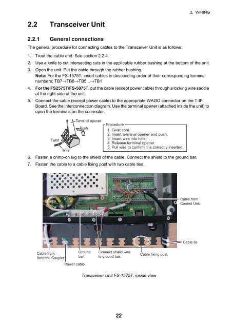
6. Fasten a crimp-on lug to the shield of the cable. Connect the shield to the ground bar.<br />
7. Fasten the cable to a cable fixing post with two cable ties.<br />
Cable from<br />
Control Unit<br />
Cable tie<br />
Cable from<br />
Antenna Coupler<br />
Ground<br />
bar<br />
Power cable<br />
Connect shield wire<br />
to ground bar.<br />
Cable fixing post<br />
Transceiver Unit FS-<strong>15</strong>75T, inside view<br />
22