FS1575_2575_5075 Installation Manual E1 6-15-2012 - Furuno USA
FS1575_2575_5075 Installation Manual E1 6-15-2012 - Furuno USA
FS1575_2575_5075 Installation Manual E1 6-15-2012 - Furuno USA

You also want an ePaper? Increase the reach of your titles
YUMPU automatically turns print PDFs into web optimized ePapers that Google loves.
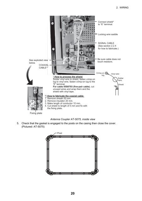
2. WIRING<br />
Connect shield*<br />
to “E” terminal.<br />
Locking wire saddle<br />
SIGNAL CABLE<br />
(See section 2.2.4<br />
for how to fabricate.)<br />
See exploded view<br />
below.<br />
COAXIAL<br />
CABLE**<br />
Be sure cable does not<br />
touch resistors.<br />
* How to process the shield:<br />
Solder vinyl wire to shield, fasten crimp-on<br />
lug to vinyl wire, fasten crimp-on lug to the<br />
“E” terminal.<br />
For cable 05S0793 (five-pair cable), cut<br />
unused wires and wrap them and the<br />
shield with vinyl tape.<br />
Crimp-on<br />
lug<br />
Vinyl wire<br />
Solder<br />
here.<br />
Shield<br />
** How to fabricate the coaxial cable:<br />
1. Remove sheath 50 mm.<br />
2. Remove insulator 20 mm.<br />
3. Make length of conductor 10 mm.<br />
4. Cut shield to length of 5 mm and fix with<br />
the fixing plate.<br />
Fixing plate<br />
Antenna Coupler AT-<strong>5075</strong>, inside view<br />
5. Check that the gasket is engaged to the posts on the casing then close the cover.<br />
(Pictured: AT-<strong>5075</strong>)<br />
Post<br />
20