FS1575_2575_5075 Installation Manual E1 6-15-2012 - Furuno USA
FS1575_2575_5075 Installation Manual E1 6-15-2012 - Furuno USA
FS1575_2575_5075 Installation Manual E1 6-15-2012 - Furuno USA

Create successful ePaper yourself
Turn your PDF publications into a flip-book with our unique Google optimized e-Paper software.
1. HOW TO INSTALL THE SYSTEM<br />
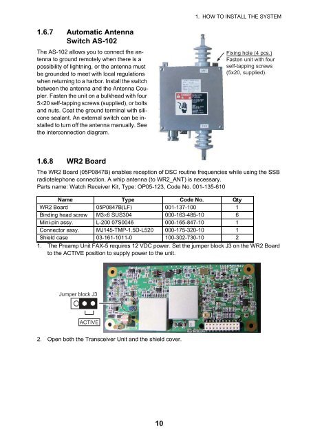
1.6.7 Automatic Antenna<br />
Switch AS-102<br />
The AS-102 allows you to connect the antenna<br />
to ground remotely when there is a<br />
possibility of lightning, or the antenna must<br />
be grounded to meet with local regulations<br />
when returning to a harbor. Install the switch<br />
between the antenna and the Antenna Coupler.<br />
Fasten the unit on a bulkhead with four<br />
5×20 self-tapping screws (supplied), or bolts<br />
and nuts. Coat the ground terminal with silicone<br />
sealant. An external switch can be installed<br />
to turn off the antenna manually. See<br />
the interconnection diagram.<br />
Fixing hole (4 pcs.)<br />
Fasten unit with four<br />
self-tapping screws<br />
(5x20, supplied).<br />
1.6.8 WR2 Board<br />
The WR2 Board (05P0847B) enables reception of DSC routine frequencies while using the SSB<br />
radiotelephone connection. A whip antenna (to WR2_ANT) is necessary.<br />
Parts name: Watch Receiver Kit, Type: OP05-123, Code No. 001-135-610<br />
Name Type Code No. Qty<br />
WR2 Board 05P0847B(LF) 001-137-100 1<br />
Binding head screw M3×6 SUS304 000-163-485-10 6<br />
Mini-pin assy. L-200 07S0046 000-165-847-10 1<br />
Connector assy. MJ145-TMP-1.5D-L520 000-175-320-10 1<br />
Shield case 03-161-1011-0 100-302-730-10 2<br />
1. The Preamp Unit FAX-5 requires 12 VDC power. Set the jumper block J3 on the WR2 Board<br />
to the ACTIVE position to supply power to the unit.<br />
Jumper block J3<br />
ACTIVE<br />
2. Open both the Transceiver Unit and the shield cover.<br />
10