FS1575_2575_5075 Installation Manual E1 6-15-2012 - Furuno USA
FS1575_2575_5075 Installation Manual E1 6-15-2012 - Furuno USA
FS1575_2575_5075 Installation Manual E1 6-15-2012 - Furuno USA

Create successful ePaper yourself
Turn your PDF publications into a flip-book with our unique Google optimized e-Paper software.
2. WIRING<br />
Locking wire<br />
saddle<br />
Cable from<br />
Antenna Coupler<br />
Cable tie<br />
Cable<br />
fixing<br />
post<br />
Power<br />
cable<br />
Ground bar<br />
Connect shield wire to<br />
ground bar.<br />
Cable from<br />
Control Unit<br />
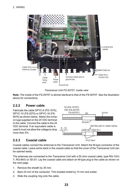
Transceiver Unit FS-<strong>5075</strong>T, inside view<br />
Note: The inside of the FS-<strong>2575</strong>T is almost identical to that of the FS-<strong>5075</strong>T. See the illustration<br />
above for connections.<br />
2.2.2 Power cable<br />
Fabricate the cable DPYC-6 (FS-<strong>15</strong>75),<br />
DPYC-10 (FS-<strong>2575</strong>) or DPYC-16 (FS-<br />
<strong>5075</strong>) as shown below. Attach the crimpon<br />
lugs supplied on the 24 VDC terminal<br />
to the cable. Connect the cable to the 24<br />
VDC terminal. If an equivalent cable is<br />
used it must not allow the voltage to drop<br />
more than 5%.<br />
70 (FS-<strong>15</strong>75T)<br />
<strong>15</strong>0 (FS-<strong>2575</strong>T,<br />
FS-<strong>5075</strong>T)<br />
8 - 10<br />
50<br />
Armor<br />
Sheath<br />
Set this part in cable clamp.<br />
20 30 20<br />
2.2.3 Coaxial cable<br />
Vinyl tape<br />
Coaxial cables connect the antennas to the Transceiver Unit. Attach the M-type connector of the<br />
coaxial cable. Leave some slack in the coaxial cable so that the cover of the Transceiver Unit can<br />
be opened easily.<br />
The antennas are connected to the Transceiver Unit with a 50 ohm coaxial cable, type RG-10/U-<br />
Y, RG-8A/U or 3D-2V. Lay the coaxial cable and attach an M-type plug to the cable as shown on<br />
the next page.<br />
1. Remove the sheath by 35 mm.<br />
2. Bare 23 mm of the conductor. Trim braided shield by 10 mm and solder.<br />
3. Slide the coupling ring onto the cable.<br />
23