FS1575_2575_5075 Installation Manual E1 6-15-2012 - Furuno USA
FS1575_2575_5075 Installation Manual E1 6-15-2012 - Furuno USA
FS1575_2575_5075 Installation Manual E1 6-15-2012 - Furuno USA

Create successful ePaper yourself
Turn your PDF publications into a flip-book with our unique Google optimized e-Paper software.
1. HOW TO INSTALL THE SYSTEM<br />
1.3 Transceiver Unit FS-<strong>15</strong>75T (FS-<strong>15</strong>75),<br />
FS-<strong>2575</strong>T (FS-<strong>2575</strong>), FS-<strong>5075</strong>T (FS-<strong>5075</strong>)<br />
Select a location that meets these conditions:<br />
• Install only on a bulkhead.<br />
• Select a location which provides good ventilation.<br />
• The location must be clean and dry.<br />
• Make sure the location can hold the unit under the conditions of continued vibration and shock<br />
normally found on the boat. If necessary, increase the strength the installation location.<br />
• Follow the compass safety distance shown in the Safety Instructions to prevent the interference<br />
to a magnetic compass.<br />
• Follow the recommended service space shown in the outline drawing to provide space for maintenance<br />
and checking.<br />
• Install the unit away from direct sunlight to prevent overheating.<br />
Fasten the unit with 6×30 self-tapping screws. Refer to the outline drawing for installation dimensions.<br />
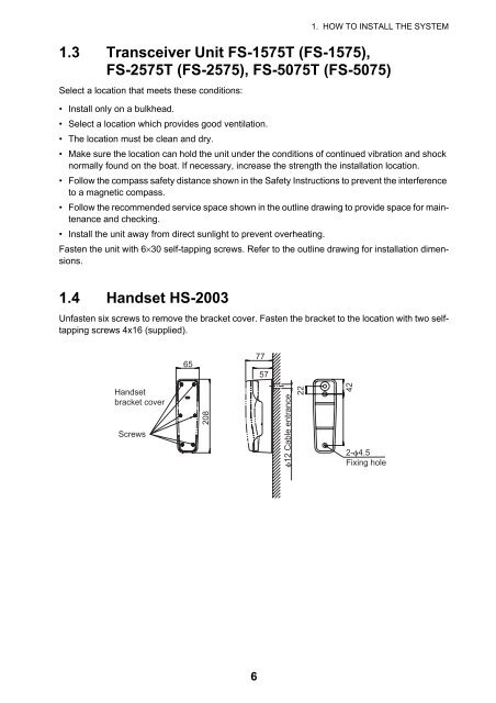
1.4 Handset HS-2003<br />
Unfasten six screws to remove the bracket cover. Fasten the bracket to the location with two selftapping<br />
screws 4x16 (supplied).<br />
65<br />
77<br />
57<br />
Handset<br />
bracket cover<br />
Screws<br />
208<br />
φ12 Cable entrance<br />
22<br />
42<br />
2-φ4.5<br />
Fixing hole<br />
6