

Den Svævende Kugle, Dokumentation [pdf - sorenr.dk
Den Svævende Kugle, Dokumentation [pdf - sorenr.dk
Den Svævende Kugle, Dokumentation [pdf - sorenr.dk

You also want an ePaper? Increase the reach of your titles
YUMPU automatically turns print PDFs into web optimized ePapers that Google loves.
<strong>Den</strong> svævende kugle<br />
6.3 Hardware<br />
6.3.7 STK500 Userguide<br />
Pull up<br />
82<br />
3.2 Description of<br />
User Switches<br />
Note: The AVR can source or sink enough current to drive a LED directly. In the<br />
STK500 design, a transistor with two resistors is used to give the same amount<br />
of light from the LED, whatever the target voltage (VTG) may be and to turn off<br />
the LEDs when VTG is missing.<br />
Ingeniørhøjskolen ˚Arhus 2005<br />
Gruppe 3<br />
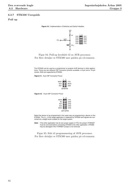
The switches connected to the debug headers are implemented as shown in Figure 3-3.<br />
Pushing a switch causes the corresponding SWx to be pulled low, while releasing it will<br />
result in VTG on the appropriate switch header connector. Valid target voltage range is<br />
1.8V < VTG < 6.0V.<br />
Figure 3-3. Implementation of Switches and Switch Headers<br />
SW n<br />
150R<br />
VTG<br />
10K<br />
SW n<br />
SW0<br />
SW2<br />
SW4<br />
SW6<br />
GND<br />
SW1<br />
SW3<br />
SW5<br />
SW7<br />
VTG<br />
Figur 84: Pull-up kredsløb til en AVR processor.<br />
For flere detaljer se STK500 user guiden p˚a cd-rommen.<br />
Note: In the AVR, the user can enable internal pull-ups on the input pins, removing the<br />
need for an external pull-up on the push-button. In the STK500 design, we have<br />
added an external External 10K pull-up to give Target all users a logical System<br />
“1” on SWn when the<br />
push-button is not pressed. The 150R resistor limits the current going into the<br />
AVR.<br />
AVR STK500 User Guide 6-1<br />
1 2<br />
Section 6<br />
In-System Programming of an<br />
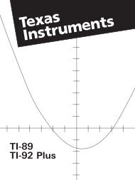
The STK500 can be used as a programmer to program AVR devices in other applications.<br />
There are two different ISP connector pinouts available: a 6-pin and a 10-pin<br />
version. Both are supported by STK500.<br />
Figure 6-1. 6-pin ISP Connector Pinout<br />
1 2<br />
3-2 MISO VTG<br />
AVR STK500 User Guide<br />
1925C–AVR–3/03<br />
SCK MOSI<br />
RST GND<br />
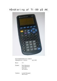
Figure 6-2. 10-pin ISP Connector Pinout<br />
MOSI<br />
NC<br />
RST<br />
SCK<br />
MISO<br />
ISP6PIN<br />
1 2<br />
ISP10PIN<br />
VTG<br />
GND<br />
GND<br />
GND<br />
GND<br />
Select the device to be programmed in the same way as programming a device on the<br />
STK500. The V CC of the target application is detected by STK500 and signals are converted<br />
into voltage levels suitable for the target system.<br />
Note: If the other application has its own power supply to VTG, the jumper VTARGET<br />
must be removed before connecting STK500 to the other application. STK500<br />
may be damaged if the VTARGET jumper is not removed.<br />
Figur 85: Stik til programmering af AVR processor.<br />
For flere detaljer se STK500 user guiden p˚a cd-rommen.<br />
Rev. 1925C–AVR–3/03
![Formelsamling B-niveau projekt [pdf] - sorenr.dk](https://img.yumpu.com/18276273/1/184x260/formelsamling-b-niveau-projekt-pdf-sorenrdk.jpg?quality=85)
![1. Semester EIT: SDS, Dokumentation [pdf] - sorenr.dk](https://img.yumpu.com/18121803/1/184x260/1-semester-eit-sds-dokumentation-pdf-sorenrdk.jpg?quality=85)