BPV 5-20-5 - TA Hydronics
BPV 5-20-5 - TA Hydronics
BPV 5-20-5 - TA Hydronics

Erfolgreiche ePaper selbst erstellen
Machen Sie aus Ihren PDF Publikationen ein blätterbares Flipbook mit unserer einzigartigen Google optimierten e-Paper Software.
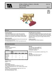
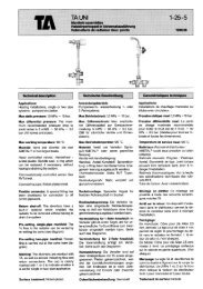
Technical description<br />
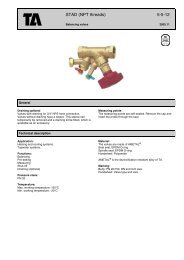
Applications:<br />
Heating, cooling and domestic hot water<br />
systems.<br />
Functions:<br />
Proportional relief, adjustable differential<br />
pressure and shut-off.<br />
Nominal pressure: PN <strong>20</strong><br />
Max working pressure:<br />
2.0 MPa = <strong>20</strong> bar ≈ 300 psi<br />
Max working temperature: 1<strong>20</strong>°C<br />
Min working temperature: -<strong>20</strong>°C<br />
Materials:<br />
Valve body, bonnet and stem:<br />
AME<strong>TA</strong>L ® .<br />
Union nuts, sleeve and cap: Brass<br />
Gaskets: Graphite<br />
Springs: Stainless steel<br />
O-rings: EPDM rubber<br />
Guide ring: PTFE<br />
Marking:<br />
Valve type, DN and inch size.<br />
<strong>BPV</strong> 5-<strong>20</strong>-5<br />
Proportional relief valve<br />
Proportionales Überströmventil<br />
Soupape de décharge proportionnelle 1997.09<br />
Technische Beschreibung<br />
Anwendungsbereich:<br />
Heizungs-, Kühl- und Brauchwasseranlagen<br />
Eigenschaften:<br />
Proportionales Überströmventil mit<br />
stufenlos einstellbaren Sollwert 10-60<br />
kPa Absperrbar.<br />
Nenndruck: PN <strong>20</strong><br />
Max. Betriebsdruck:<br />
2,0 MPa = <strong>20</strong> bar<br />
Max. Betriebstemperatur: 1<strong>20</strong>°C<br />
Min. Betriebstemperatur: -<strong>20</strong>°C<br />
Material:<br />
Gehäuse, Kegel, Oberteil und Spindel<br />
aus AME<strong>TA</strong>L ® .<br />
Anschlußmutter, Hülse und Kappe aus<br />
Messing.<br />
Flachdichtungen aus Graphit.<br />
Feder aus rostfreiem Stahl.<br />
O-Ring aus EPDM-Gummi.<br />
Führungsring aus PTFE.<br />
Kennzeichnung:<br />
Ventiltyp, DN und Zollangabe.<br />
Menu<br />
T O U R & A N D E R S S O N H Y D R O N I C S A B<br />
ISO 9001<br />
Certification of Registration<br />
Number FM 1045<br />
Certified by BSI<br />
Q U A L I T Y<br />
S Y S T E M<br />
Caractéristiques techniques<br />
Application:<br />
Installations de chauffage et de<br />
conditionnement d'air.<br />
Fonctions:<br />
Limitation de la pression différentielle<br />
par décharge proportionnelle. Consigne<br />
réglable de 10 à 60 kPa. Fonction<br />
d'isolation.<br />
Pression nominale: PN <strong>20</strong><br />
Pression de service maxi:<br />
2,0 MPa = <strong>20</strong> bar<br />
Température de service maxi: 1<strong>20</strong>°C<br />
Température de service mini: -<strong>20</strong>°C<br />
Matériaux:<br />
Corps, clapet, chapeau et tige en<br />
AME<strong>TA</strong>L ® .<br />
Ecrou, raccord et couvercle en laiton.<br />
Joints en graphite.<br />
Ressorts en inox.<br />
Joints toriques en caoutchouc EPDM.<br />
Guide de tige en PTFE.<br />
Marquage:<br />
Type de vanne, DN/pouce.
General<br />
<strong>BPV</strong> is a proportional relief valve for use<br />
in heating and cooling installations.<br />
In installations with radiator valves, in<br />
which many of the radiator valves have<br />
closed, a big part of the pump head will<br />
affect the valves since the pressure<br />
drop in pipes and accessories has<br />
decreased. If the available differential<br />
pressure is higher than 30 kPa, noise<br />
may occur.<br />
Installation of <strong>BPV</strong><br />
Install the <strong>BPV</strong> in the circuit after the<br />
balancing valve and between the supply<br />
and return pipe. The <strong>BPV</strong> is adjustable<br />
and opens at the preset differential<br />
pressure, making it possible to maintain<br />
desired pressure and flow in the<br />
distribution system.<br />
Da<br />
Allgemeines<br />
<strong>BPV</strong> ist ein proportionales Überströmventil<br />
zur Installation in Heizungs- und<br />
Kühlanlagen.<br />
Bei Anlagen mit thermostatischen<br />
Heizkörperventilen nimmt der Druckverlust<br />
in den Rohrleitungen und Rohreinbauteilen<br />
stark ab, wenn mehrere<br />
Ventile schließen. Aus diesem Grund<br />
steigt der Differensdruck für die noch<br />
geöffneten Ventile. Ist der anstehende<br />
Differenzdruck >30 kPa, können<br />
störende Geräusche an den Thermostatventilen<br />
entstehen.<br />
Installation des <strong>BPV</strong><br />
Das <strong>BPV</strong>-Ventil wird im System nach<br />
dem Einregulierungsventil zwischen<br />
Vor- und Rücklauf installiert. Das <strong>BPV</strong>-<br />
Ventil ist stufenlos einstellbar und öffnet<br />
erst ab dem eingestellten Sollwert. So<br />
ist es möglich, sowohl den Differenzdruck<br />
als auch den Durchfluß im<br />
Verteilungsnetz konstant zu halten.<br />
Généralités<br />
La <strong>BPV</strong> est une vanne de décharge<br />
proportionnelle prévue pour les installations<br />
de chauffage et de conditionnement d’air.<br />
Dans les installations de chauffage par<br />
radiateurs équipés de robinets thermostatiques,<br />
l’ensoleillement ou les apports<br />
internes peuvent conduire à la fermeture<br />
d’un certain nombre de robinets. Dans ce<br />
cas, le débit dans les conduites diminue et<br />
la pression différentielle appliquée sur les<br />
robinets augmente. Si cette pression<br />
différentielle dépasse 30 kPa, l’installation<br />
risque de devenir bruyante.<br />
Installation de la <strong>BPV</strong><br />
La <strong>BPV</strong> est placée entre les conduites<br />
d’alimentation et de retour du circuit<br />
concerné (voir figure de principe ci-après).<br />
Dès que la pression différentielle atteint la<br />
consigne choisie, la <strong>BPV</strong> commence à<br />
s’ouvrir. La pression différentielle appliquée<br />
au circuit est ainsi limitée et reste proche de<br />
la valeur choisie pour le calcul des robinets<br />
de radiateur ou des vannes de régulation<br />
des unités terminales.<br />
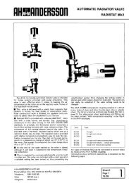
<strong>TA</strong> No<br />
<strong>TA</strong> Nr<br />
No <strong>TA</strong> DN D L H<br />
Adjustable range 10-60 kPa./Einstellbereich 10-60 kPa./Plage de réglage 10-60 kPa.<br />
52 198-315 15 G1/2 70 93<br />
52 198-3<strong>20</strong> <strong>20</strong> G3/4 85 93<br />
52 198-325 25 G1 98 103<br />
52 198-332 32 G1 1/4 112 105<br />
<strong>TA</strong> No<br />
<strong>TA</strong> Nr<br />
No <strong>TA</strong> DN d D Da L H<br />
Adjustable range 10-60 kPa./Einstellbereich 10-60 kPa./Plage de réglage 10-60 kPa.<br />
52 198-0<strong>20</strong> <strong>20</strong> R3/4 G3/4 M34x1,5 70 122<br />
52 198-025 25 R1 G1 M40x2 83 138<br />
<strong>BPV</strong> DN 15 and DN <strong>20</strong> can be connected to smooth pipes with KOMBI compression couplings.<br />
<strong>BPV</strong> DN 15 und DN <strong>20</strong> kann mit Klemmringverschraubungen KOMBI auch an glatte Rohre angeschlossen werden.<br />
Les modèles <strong>BPV</strong> DN 15 et DN <strong>20</strong> peuvent se raccorder à des tuyaux lisses à l'aide des raccords à compression<br />
KOMBI.<br />
Size/Größe/Dimension Pipe/Rohr/Tubes (mm)<br />
Inches/<br />
Zoll/Pouces DN 8 10 12 15 16 18 22<br />
1/2 15 53 235-108 53 235-109 53 235-111 53 235-113 53 235-114<br />
3/4 <strong>20</strong> -117 -119 53 235-121 53 235-123<br />
KOMBI compression couplings are ordered separately. For further information about KOMBI, see section 4 in the catalogue.<br />
KOMBI ist gesondert zu bestellen. Weitere Information über KOMBI unter Abschnitt 4.<br />
Les raccords KOMBI doivent faire l'objet de commandes séparées. Pour plus de détails, voir intercalaire 4.<br />
Menu
Menu<br />
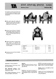
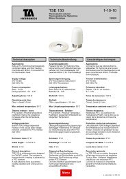
Balancing/Einregulierung/Equilibrage<br />
See the following manuals for<br />
descriptions of various adjustments<br />
methods:<br />
Handbook no. 1: Balancing control<br />
circuits<br />
Handbook no. 2: Balancing distribution<br />
systems<br />
Handbook no. 3: Balancing radiator<br />
systems<br />
Total hydronic balancing<br />
Use an Allen key to adjust the <strong>BPV</strong><br />
valve to operate at the required differential<br />
pressure.<br />
Zur Beschreibung der verschiedenen<br />
Einregulierungsverfahren siehe:<br />
Handbuch Nr. 1: Die hydraulische<br />
Einregulierung von<br />
Regelkreisen<br />
Handbuch Nr. 2: Die hydraulische<br />
Einregulierung von<br />
Verteilungssystemen<br />
Handbuch Nr. 3: Einregulierung von<br />
Heizkörpersystemen<br />
EINREGULIERUNG - TO<strong>TA</strong>L<br />
q p<br />
ΔH<br />
STS<br />
S<strong>TA</strong>D<br />
<strong>BPV</strong><br />
A<br />
B<br />
q s<br />
Verwenden Sie einen Inbusschlüssel,<br />
um das <strong>BPV</strong>-Ventil auf den erforderlichen<br />
Differenzdruck einzustellen.<br />
V<br />
C<br />
V<br />
C<br />
Pour la description des différentes<br />
méthodes d'équilibrage, voir:<br />
Manuel no 1: Comment équilibrer<br />
hydrauliquement les<br />
circuits de régulation<br />
Manuel no 2: L'équilibrage des<br />
systèmes de distribution<br />
Manuel no 3: L'équilibrage des<br />
systèmes de radiateurs<br />
L'équilibrage hydraulique global<br />
Les vannes BVP sont réglables à la<br />
pression différentielle souhaitée à l’aide<br />
d’une clé Allen.
Valve characteristics/Technische Eigenschaften/Tableau technique<br />
Adjust the <strong>BPV</strong> valve to the required<br />
differential pressure (10-60 kPa). The<br />
valve characteristics will be as shown in<br />
the diagrams below.<br />
Das <strong>BPV</strong>-Ventil wird auf den<br />
gewünschten Differenzdruck (10-60<br />
kPa) eingestellt. Sobald dieser erreicht<br />
wird, öffnet das Ventil und führt<br />
entsprechend den nachfolgenden<br />
Diagrammen die Regelung durch.<br />
*) Differential pressure setting./Eingestellter Differenzdruck./Pression différentielle consignée.<br />
Régler la consigne de la BVP à la<br />
valeur souhaitée (10 à 60 kPa). La<br />
pression différentielle obtenue évolue<br />
en fonction du débit traversant la <strong>BPV</strong><br />
selon les diagrammes ci-dessous.<br />
<strong>TA</strong> <strong>Hydronics</strong> reserves the right to make changes to products and specifications without prior notice.<br />
Änderungen der Ausführung und der Spezifikationen bleiben vorbehalten.<br />
Tous droits de modification réservés sans avis préalable.<br />
Menu
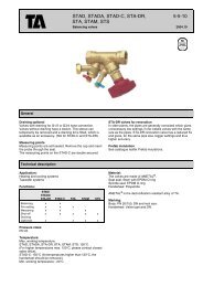
Mounting instructions for <strong>BPV</strong> differential<br />
pressure stabilizer<br />
<strong>BPV</strong> is a proportional relief valve for use in heating and cooling<br />
installations.<br />
In installations with radiator valves, in which many of the radiator valves<br />
have closed, a big part of the pump head will affect the valves since the<br />
pressure drop in pipes and accessories has decreased. If the available<br />
differential pressure is higher than 30 kPa, noise may occur.<br />
Installation of <strong>BPV</strong><br />
Install the <strong>BPV</strong> in the circuit after the balancing valve and between the<br />
supply and return pipe. The <strong>BPV</strong> is adjustable and opens at the preset<br />
differential pressure, making it possible to maintain desired pressure and<br />
flow in the distribution system.<br />
Balancing the plant<br />
The plant should be balanced while in operation and with the <strong>BPV</strong> valves<br />
closed. All thermostatic valves should first be set for a pressure drop of,<br />
for example, 10 kPa at design flow. Decrease the supply water temperature<br />
so that all thermostatic valves are fully open. The design flow in the<br />
circuit is then set in the normal way by means of a CBI.<br />
The <strong>BPV</strong> is set to the desired pressure drop with an allen key.<br />
Δp <strong>BPV</strong> = Δp rad + Δp marginal , eg Δp <strong>BPV</strong> = 10 kPa + 2 kPa = 12 kPa<br />
q p<br />
ΔH<br />
STS<br />
S<strong>TA</strong>D<br />
<strong>BPV</strong><br />
A<br />
B<br />
<strong>BPV</strong><br />
q s<br />
V<br />
C<br />
V<br />
C<br />
Menu<br />
T O U R & A N D E R S S O N H Y D R O N I C S A B<br />
ISO 9001<br />
Certification of Registration<br />
Number FM 1045<br />
Certified by BSI<br />
Montageanleitung für <strong>BPV</strong> Differnzdruckstabilisator<br />
<strong>BPV</strong> ist ein proportionales Überströmventil zur Installation in Heizungsund<br />
Kühlanlagen.<br />
Bei Anlagen mit thermostatischen Heizkörperventilen nimmt der Druckverlust<br />
in den Rohrleitungen und Rohreinbauteilen stark ab, wenn<br />
mehrere Ventile schließen. Aus diesem Grund steigt der Differens-druck<br />
für die noch geöffneten Ventile. Ist der anstehende Differenz-druck >30<br />
kPa, können störende Geräusche an den Thermostat-ventilen entstehen.<br />
Installation des <strong>BPV</strong><br />
Das <strong>BPV</strong>-Ventil wird im System nach dem Einregulierungsventil zwischen<br />
Vor- und Rücklauf installiert. Das <strong>BPV</strong>-Ventil ist stufenlos einstellbar und<br />
öffnet erst ab dem eingestellten Sollwert. So ist es möglich, sowohl den<br />
Differenzdruck als auch den Durchfluß im Ver-teilungsnetz konstant zu<br />
halten.<br />
Einregulierung der Anlage<br />
Die Einregulierung erfolgt während des Betriebes und bei geschlossenem<br />
<strong>BPV</strong>. Die Thermostatventile sind so einzustellen, daß der Druckverlust<br />
bei Nenndurchflußmenge z.B. 10 kPa beträgt. Ein Öffnen der<br />
Thermostatventile kann durch Absenken der Vorlauftemperatur erreicht<br />
werden. Als Folge sinkt auch die Raumtemperatur und alle<br />
Thermostatventile öffnen voll. Die Nenndurchflußmenge im<br />
Verbraucherkreis wird mit Hilfe des CBI-Meßgerätes einreguliert. Danach<br />
wird das <strong>BPV</strong>-Ventil mit einem Inbusschlüssel auf den gewünschten<br />
Differenzdruck Δp eingestellt.<br />
Δp <strong>BPV</strong> = Δp Heizkörper +Δp Verb. , d.h. Δp <strong>BPV</strong> = 10 kPa + 2 kPa = 12 kPa.<br />
Q U A L I T Y<br />
307 865-01<br />
95.11<br />
S Y S T E M<br />
Use a 3 mm Allen key to set the<br />
opening pressure.<br />
To shut the valve turn clockwise until<br />
it stops.<br />
Benutzen Sie zum Einstellen des<br />
Öffnungsdruckes einen 3 mm-<br />
Innensechskant-Schlüssel. Um das<br />
Ventil zu schließen, müssen Sie im<br />
Uhrziegersinn bis zum Anschlag<br />
drehen.