WellChrom Filter-Photometer K-2001 Filterphotometer K-2001 ...
WellChrom Filter-Photometer K-2001 Filterphotometer K-2001 ...
WellChrom Filter-Photometer K-2001 Filterphotometer K-2001 ...

Erfolgreiche ePaper selbst erstellen
Machen Sie aus Ihren PDF Publikationen ein blätterbares Flipbook mit unserer einzigartigen Google optimierten e-Paper Software.
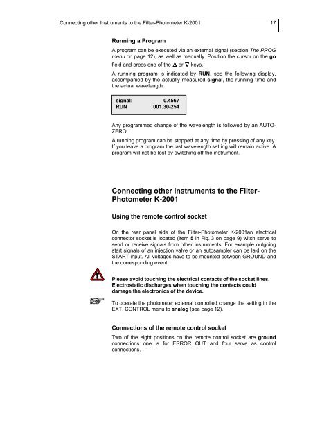
Connecting other Instruments to the <strong>Filter</strong>-<strong>Photometer</strong> K-<strong>2001</strong> 17<br />
Running a Program<br />
A program can be executed via an external signal (section The PROG<br />
menu on page 12), as well as manually. Position the cursor on the go<br />
field and press one of the or keys.<br />
A running program is indicated by RUN, see the following display,<br />
accompanied by the actually measured signal, the running time and<br />
the actual wavelength.<br />
signal: 0.4567<br />
RUN 001.30-254<br />
Any programmed change of the wavelength is followed by an AUTO-<br />
ZERO.<br />
A running program can be stopped at any time by pressing of any key.<br />
If you leave a program the last wavelength setting will remain active. A<br />
program will not be lost by switching off the instrument.<br />
Connecting other Instruments to the <strong>Filter</strong>-<br />
<strong>Photometer</strong> K-<strong>2001</strong><br />
Using the remote control socket<br />
On the rear panel side of the <strong>Filter</strong>-<strong>Photometer</strong> K-<strong>2001</strong>an electrical<br />
connector socket is located (item 5 in Fig. 3 on page 9) witch serve to<br />
send or receive signals from other instruments. For example outgoing<br />
start signals of an injection valve or an autosampler can be laid on the<br />
START input. All voltages have to be mounted between GROUND and<br />
the corresponding event.<br />
Please avoid touching the electrical contacts of the socket lines.<br />
Electrostatic discharges when touching the contacts could<br />
damage the electronics of the device.<br />
To operate the photometer external controlled change the setting in the<br />
EXT. CONTROL menu to analog (see page 12).<br />
Connections of the remote control socket<br />
Two of the eight positions on the remote control socket are ground<br />
connections one is for ERROR OUT and four serve as control<br />
connections.