Emergency Lighting Device CLS 24 - 7Ah CLS 24/SV CLS Power ...
Emergency Lighting Device CLS 24 - 7Ah CLS 24/SV CLS Power ...
Emergency Lighting Device CLS 24 - 7Ah CLS 24/SV CLS Power ...

Erfolgreiche ePaper selbst erstellen
Machen Sie aus Ihren PDF Publikationen ein blätterbares Flipbook mit unserer einzigartigen Google optimierten e-Paper Software.
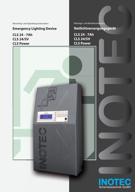
Mounting- and Operating Instructions<br />
<strong>Emergency</strong> <strong>Lighting</strong> <strong>Device</strong><br />
<strong>CLS</strong> <strong>24</strong> - <strong>7Ah</strong><br />
<strong>CLS</strong> <strong>24</strong>/<strong>SV</strong><br />
<strong>CLS</strong> <strong>Power</strong><br />
Montage- und Betriebsanleitung<br />
Notlichtversorgungsgerät<br />
<strong>CLS</strong> <strong>24</strong> - <strong>7Ah</strong><br />
<strong>CLS</strong> <strong>24</strong>/<strong>SV</strong><br />
<strong>CLS</strong> <strong>Power</strong><br />
1 Sicherheitstechnik GmbH
Montage- und Betriebsanleitung<br />
Mounting- and Operating Instructions<br />
Notlichtversorgungsgerät<br />
<strong>CLS</strong> <strong>24</strong> - <strong>7Ah</strong><br />
<strong>CLS</strong> <strong>24</strong>/<strong>SV</strong><br />
<strong>CLS</strong> <strong>Power</strong><br />
<strong>Emergency</strong> <strong>Lighting</strong> <strong>Device</strong><br />
<strong>CLS</strong> <strong>24</strong> - <strong>7Ah</strong><br />
<strong>CLS</strong> <strong>24</strong>/<strong>SV</strong><br />
<strong>CLS</strong> <strong>Power</strong><br />
3
<strong>CLS</strong> <strong>24</strong>/<strong>SV</strong> Montage- und Betriebsanleitung<br />
Inhalt<br />
1. Allgemeine Hinweise 5<br />
1.1. Symbolerklärung 5<br />
1.2. Haftung und Gewährleistung 5<br />
1.3. Ersatzteile 5<br />
1.4. Entsorgung 5<br />
1.5. Fehlerbeseitigung 5<br />
2. Sicherheitshinweise 6<br />
2.1. Bedienungsanleitung 6<br />
2.2. Reparaturen 6<br />
3. Transport und Lagerung 6<br />
3.1. Kontrolle bei Anlieferung 6<br />
3.2. Lagerung 6<br />
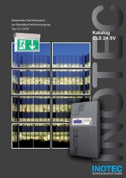
4. Produktbeschreibung 7<br />
4.1. Aufbau der <strong>CLS</strong>-Geräte 8<br />
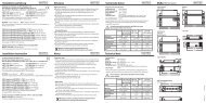
5. Technische Daten 10<br />
5.1 <strong>CLS</strong> <strong>24</strong> - <strong>7Ah</strong> 10<br />
5.2 <strong>CLS</strong> 11<br />
5.3 <strong>CLS</strong> <strong>Power</strong> 12<br />
6. Montage 12<br />
6.1. Gerät 13<br />
6.2. Batterie 13<br />
6.3. Elektrischer Anschluss 14<br />
7. Inbetriebnahme des <strong>CLS</strong>-Gerätes 21<br />
7.1. Ausschalten des <strong>CLS</strong>-Gerätes 21<br />
7.2. Einschalten des <strong>CLS</strong>-Gerätes 21<br />
7.3. Lieferzustand 21<br />
8. Bedienung 22<br />
8.1. Menüstruktur 23<br />
8.2. „Testmenü“ <strong>24</strong><br />
8.3. „Programmierung“ 25<br />
8.4. „Informationen“ 33<br />
8.5 Blockierung aufheben 36<br />
9. Störungssuche 36<br />
10. INOWEB 38<br />
10.1. Bedienung 38<br />
10.2. Störungsausdruck 39<br />
10.3. Automatische Email 40<br />
10.4. Programmierung 41<br />
11. Prüfungen 46<br />
11.1 Erstprüfungen 48<br />
11.2. Wiederkehrende Prüfungen der elektrischen<br />
Anlagen für Sicherheitszwecke 48<br />
11.3. Batterieinspektion und –überwachung 50<br />
11.4. Protokolle zu wiederkehrenden Prüfungen 50<br />
Anhang 51<br />
A. Kopiervorlage für die Anlagendokumentation 51<br />
B. Stromaufnahmetabellen 55<br />
C. Leitungslängen 55<br />
D. Kundendienst 55<br />
<strong>CLS</strong> <strong>24</strong>/<strong>SV</strong> Mounting and Operating Instructions<br />
Contents<br />
1. General information 5<br />
1.1. Explanation of symbols 5<br />
1.2. Liability and warranty 5<br />
1.3. Spare parts 5<br />
1.4. Disposal 5<br />
1.5. Correction of faults 5<br />
2. Safety instructions 6<br />
2.1. Operating instructions 6<br />
2.2. Repairs 6<br />
3. Transport and storage 6<br />
3.1. Examination on delivery 6<br />
3.2. Storage 6<br />
4. Product description 7<br />
4.1. Design and structure of <strong>CLS</strong> devices 8<br />
5. Technical data 10<br />
5.1 <strong>CLS</strong> <strong>24</strong> - <strong>7Ah</strong> 10<br />
5.2 <strong>CLS</strong> 10<br />
5.3 <strong>CLS</strong> <strong>Power</strong> 12<br />
6. Mounting 12<br />
6.1. <strong>Device</strong> 13<br />
6.2. Battery 13<br />
6.3. Electrical connection 14<br />
7. Commissioning the <strong>CLS</strong> device 21<br />
7.1. Switching OFF the <strong>CLS</strong> device 21<br />
7.2. Switching ON the <strong>CLS</strong> device 21<br />
7.3. Factory settings 21<br />
8. Use 22<br />
8.1. Menu structure 23<br />
8.2. "Test menu" <strong>24</strong><br />
8.3. "Programming" 25<br />
8.4. "Information" 33<br />
8.5 Unblock system 36<br />
9. Troubleshooting 36<br />
10. INOWEB 38<br />
10.1. Use 38<br />
10.2. Printing out the fault 39<br />
10.3. Automatic email 40<br />
10.4. Programming 41<br />
11. Tests 48<br />
11.1 Initial tests 48<br />
11.2. Recurring safety tests on electrical systems 48<br />
11.3. Battery inspection and monitoring. 50<br />
11.4. Protocols for repeat tests 50<br />
Appendix 51<br />
A. Copy template for system documentation 51<br />
B. Input power charts 55<br />
C. Wire lengths 55<br />
D. Customer service 55<br />
4
<strong>CLS</strong> <strong>24</strong>/<strong>SV</strong> Montage- und Betriebsanleitung<br />
1. Allgemeine Hinweise<br />
1.1. Symbolerklärung<br />
Sicherheitsrelevante Informationen sind durch<br />
nebenstehendes Symbol gekennzeichnet. Eine<br />
Nichtbefolgung der Anweisungen kann zu Personenschäden<br />
oder defektem Gerät führen!<br />
Hinweise liefern wichtige Informationen und<br />
sind mit einem gelben Symbol markiert. Bitte<br />
lesen Sie diese sehr aufmerksam.<br />
Dieses Symbol macht Sie auf zusätzliche Informationen<br />
aufmerksam.<br />
<strong>CLS</strong> <strong>24</strong>/<strong>SV</strong> Mounting and Operating Instructions<br />
1. General information<br />
1.1. Explanation of symbols<br />
This symbol highlights important information<br />
in the mounting and operating instructions that<br />
also concerns safety. Failure to follow the instructions<br />
may result in personal injury or breakage!<br />
Instructions marked by a yellow icon provide<br />
important information. Please read this very<br />
carefully.<br />
This icon provides additional information.<br />
1.2. Haftung und Gewährleistung<br />
INOTEC übernimmt keine Gewährleistung<br />
oder Haftung für Schäden oder Folgeschäden,<br />
die entstehen durch<br />
• Nicht bestimmungsgemäßen Gebrauch<br />
• Nichteinhaltung von Vorschriften für den sicheren<br />
Betrieb<br />
• Betrieb von nicht zugelassenen oder ungeeigneten<br />
Komponenten am Notlichtsystem<br />
• Bei fehlerhafter Installation<br />
• Bei Eingriff in das Gerät<br />
1.3. Ersatzteile<br />
Defekte Bauteile dürfen nur gegen INOTEC-Original-<br />
Ersatzteile ausgetauscht werden. Nur bei diesen Teilen<br />
gewährleisten wir, dass Sie die Sicherheitsanforderungen<br />
im vollen Umfang erfüllen. Garantie-, Service- und Haftpflichtansprüche<br />
erlöschen bei Verwendung nicht geeigneter<br />
Ersatzteile.<br />
Der Einsatz von fehlerhaften Ersatzteilen kann zu<br />
fehlerhaftem Betrieb oder einem nicht funktionierendem<br />
System führen.<br />
1.4. Entsorgung<br />
Von INOTEC gelieferte Batterien und Elektronikbauteile<br />
können an INOTEC zurückgegeben werden oder sind<br />
gemäß den nationalen Richtlinien und Vorschriften für<br />
die Entsorgung von Alt-Batterien und Elektronikbauteilen<br />
zu entsorgen.<br />
1.5. Fehlerbeseitigung<br />
Nach jeder Fehlerbeseitigung der angeschlossenen<br />
Leuchten muss ein Funktionstest ausgelöst<br />
werden, um den angezeigten Fehler zu löschen.<br />
8.2.1. Funktionstest starten - Seite <strong>24</strong><br />
1.2. Liability and warranty<br />
INOTEC does not accept any responsibility or liability<br />
whatsoever for damage or consequential damage<br />
caused by:<br />
• failure to operate devices according to their<br />
intended use<br />
• failure to follow instructions relating to safe operation<br />
• the use of unauthorized or unsuitable components<br />
in conjunction with the emergency lighting system<br />
• faulty installation<br />
• opening the device<br />
1.3. Spare parts<br />
Defective components must only be replaced with<br />
original INOTEC spare parts. We cannot guarantee that<br />
safety requirements are fully met if parts other than<br />
these are used. No warranty, service or liability claims<br />
will be acknowledged if unsuitable spare parts are used.<br />
The use of defective spare parts may result in malfunction<br />
or cause the system the fail entirely.<br />
1.4. Disposal<br />
Batteries and electronic components supplied by INO-<br />
TEC can be returned to INOTEC, or should be disposed of<br />
in accordance with the national guidelines and regulations<br />
governing the disposal of used batteries and electronic<br />
components.<br />
1.5. Correction of faults<br />
Whenever a fault associated with connected luminaires<br />
is corrected, a function test must be carried<br />
out to reset the fault indication. 8.2.1. Running<br />
a function test - page <strong>24</strong><br />
5
<strong>CLS</strong> <strong>24</strong>/<strong>SV</strong> Montage- und Betriebsanleitung<br />
2. Sicherheitshinweise<br />
Die Installation darf nur durch Elektrofachkräfte<br />
erfolgen.<br />
Das Gerät ist bestimmungsgemäß und nur im einwandfreien,<br />
unbeschädigten Zustand zu betreiben.<br />
Für die Installation und den Betrieb dieses Gerätes sind<br />
die nationalen Sicherheits- und Unfallverhütungsvorschriften<br />
zu beachten.<br />
Vor Arbeiten an dem Gerät, insbesondere beim Austausch<br />
von Baugruppen, ist die Anlage spannungsfrei zu<br />
schalten (Netz- und Batteriespannung)! 7. Inbetriebnahme<br />
des <strong>CLS</strong>-Gerätes - Seite 21<br />
Elektrische Bauteile, wie LEDs, sind<br />
empfindlich gegen elektrostatische<br />
Entladung und können<br />
bereits beim Berühren der<br />
Anschlüsse zerstört werden.<br />
Für die Montage sind geeignete ESD-Schutzmaßnahmen<br />
zu treffen!<br />
2.1. Bedienungsanleitung<br />
Lesen Sie vor der Montage- und Inbetriebnahme<br />
die Montage- und Betriebsanleitung. Sie gibt<br />
wichtige Informationen für die Sicherheit, den<br />
Gebrauch und die Wartung des Gerätes. Dadurch schützen<br />
Sie sich und verhindern Schäden am Gerät.<br />
2.2. Reparaturen<br />
Eventuelle Reparaturen oder Eingriffe dürfen ausschließlich<br />
durch INOTEC autorisierte Personen vorgenommen<br />
werden.<br />
3. Transport und Lagerung<br />
3.1. Kontrolle bei Anlieferung<br />
Überprüfen Sie das Gerät bei Anlieferung unverzüglich<br />
auf Vollständigkeit und äußere Beschädigungen. Melden<br />
Sie dem Spediteur offensichtliche Beschädigungen<br />
sofort, da wir spätere Reklamationen nicht anerkennen.<br />
<strong>CLS</strong> <strong>24</strong>/<strong>SV</strong> Mounting and Operating Instructions<br />
2. Safety instructions<br />
Installation should only be carried out by electricians<br />
qualified and trained.<br />
The device must not be used for anything other than its<br />
intended purpose and only in a perfect and undamaged<br />
condition.<br />
When installing and operating this device, please follow<br />
your national safety and accident prevention regulations<br />
at all times.<br />
Before carrying out any work on the device, in particular<br />
when replacing components, always disconnect the<br />
system from the power source (mains and battery).<br />
7. Commissioning the <strong>CLS</strong> device - page 21<br />
Electrical components (e.g. LEDs)<br />
are sensitive to electrostatic<br />
discharge(ESD) and can already be<br />
destroyed when touching the terminals.<br />
Please observe suitable ESD protective measures<br />
while mounting.<br />
2.1. Operating instructions<br />
Always read the mounting and operating instructions<br />
before installing and commissioning the<br />
device. These instructions contain important<br />
information on the safety, use and maintenance of the<br />
device, and will protect you and prevent damage to the<br />
system.<br />
2.2. Repairs<br />
Any repairs which need to be carried out or which<br />
involve opening the device must ONLY be carried out<br />
by personnel authorized to do so by INOTEC.<br />
3. Transport and storage<br />
3.1. Examination on delivery<br />
Please examine the device carefully at point of receipt<br />
to ensure complete delivery and that no external damage<br />
exists. Please inform the carrier immediately if there<br />
are any signs of damage — we regret that we are unable<br />
to acknowledge complaints submitted after this point.<br />
6<br />
3.2. Lagerung<br />
Das Gerät ist bis zur Montage wie folgt zu lagern:<br />
• Nicht im Freien aufbewahren<br />
• Trocken und staubfrei lagern<br />
Für die eingebauten Batterien gilt:<br />
• Batterien dürfen max. 3 Monate ohne Ladung gelagert<br />
werden<br />
• Bei längerer Unterbrechung der Netzversorgung muss<br />
der Batteriekreis durch entfernen der Batteriesicherung<br />
gemäß Betriebsanleitung freigeschaltet werden<br />
7. Inbetriebnahme des <strong>CLS</strong>-Gerätes - Seite 21<br />
• Vor der ersten Funktionsprüfung sind die Batterien min.<br />
<strong>24</strong> Stunden zu laden<br />
3.2. Storage<br />
Until assembly, please observe the following regarding<br />
storage of the device:<br />
• Do not store in the open air<br />
• Do store in a dry, dust-free environment<br />
The following applies to batteries that have already<br />
been fitted:<br />
• Batteries must not be stored for more than 3 months<br />
without being charged<br />
• If the mains supply is interrupted for an extended<br />
period of time, the battery circuit must be disconnected<br />
by removing the battery fuse in accordance with the<br />
operating instructions – 7. Commissioning the <strong>CLS</strong><br />
device - page 21<br />
• Charge the batteries for at least <strong>24</strong> hours before carrying<br />
out the initial function test
<strong>CLS</strong> <strong>24</strong>/<strong>SV</strong> Montage- und Betriebsanleitung<br />
4. Produktbeschreibung<br />
Die dezentrale INOTEC Notlichtanlage <strong>CLS</strong> <strong>24</strong> ist ein Versorgungsgerät<br />
in Schutzklasse I für den Betrieb und die<br />
Überwachung von bis zu 80 Sicherheits- und Rettungszeichenleuchten.<br />
Je Abgang können bis zu 20 Leuchten<br />
in unterschiedlichen Schaltungsarten betrieben werden.<br />
Das <strong>CLS</strong> System beinhaltet:<br />
• Batterie für 1 Std., 3 Std. oder 8 Std. Notlichtbetrieb<br />
• 4 Stromkreisabgänge, geeignet für bis zu 20 Leuchten<br />
mit einer maximalen Anschlussleistung von max. 3A je<br />
Stromkreis (<strong>CLS</strong> <strong>24</strong>/<strong>SV</strong> und <strong>CLS</strong> <strong>Power</strong>)<br />
• 2 Stromkreisabgänge, geeignet für bis zu 20 Leuchten<br />
(<strong>CLS</strong> <strong>24</strong> - <strong>7Ah</strong>)<br />
• Steuerteil mit vierzeiligem Display für<br />
Statusinformationen<br />
• 4-kanaliger Lichtschalterabfrage<br />
• Integriertes Prüfbuch<br />
• Optionales Netzwerkmodul INOWEB<br />
Die Leuchten werden über eine zweiadrige Versorgungsleitung<br />
mit <strong>24</strong>V-Schutzkleinspannung versorgt<br />
und können über das Gerätesteuerteil programmiert<br />
werden. Dabei wird der eindeutigen Leuchtenadresse<br />
eine logische Verknüpfung mit einer Stromkreisadresse<br />
zugewiesen.<br />
Das frei programmierbare Steuerteil hat vier Status-LED<br />
und ein vierzeiliges alphanummerisches Display zur<br />
Anzeige des jeweiligen Geräte- und Leuchtenzustandes.<br />
Über die serienmäßig integrierte PS/2-Schnittstelle<br />
können Textinformation zu den einzelnen Leuchten mit<br />
einer handelsüblichen Tastatur erfasst werden.<br />
Jederzeit können manuelle Tests zur Überprüfung ausgelöst<br />
werden. Ebenso sind automatische Tests zu frei programmierbaren<br />
Zeitpunkten möglich. Die Testergebnisse<br />
werden im integrierten Prüfbuch detailliert gespeichert<br />
und sind jederzeit abrufbar (ca. 1.000 Einträge).<br />
Vier potentialfreie Kontakte zur externen Fehlermeldung/Statusanzeige<br />
sind vorhanden. Einer dieser Kontakte<br />
ist frei programmierbar.<br />
Über ein optionales Netzwerkmodul kann der Zustand<br />
überall im Netzwerk per Webbrowser abgerufen werden.<br />
Der Zugriff auf die HTML-Seiten ist über ein frei wählbares<br />
Passwort zu schützen.<br />
<strong>CLS</strong> <strong>24</strong>/<strong>SV</strong> Mounting and Operating Instructions<br />
4. Product description<br />
The <strong>CLS</strong> <strong>24</strong> local INOTEC emergency lighting system is<br />
a protection class I supply device for using and monitoring<br />
up to 80 safety and emergency exit luminaires. You<br />
can operate up to 20 luminaires with different switching<br />
modes for each outgoing circuit.<br />
The <strong>CLS</strong> system includes:<br />
• Battery for 1 h, 3 h or 8 hours of emergency lighting<br />
• 4 outgoing circuits designed for up to 20 luminaires<br />
with a maximum connected output of max. 3A per<br />
circuit(<strong>CLS</strong> <strong>24</strong>/<strong>SV</strong> und <strong>CLS</strong> <strong>Power</strong>)<br />
• 2 outgoing circuits designed for up to20 luminaires (<strong>CLS</strong><br />
<strong>24</strong> - <strong>7Ah</strong>)<br />
• Controller with 4-row display for status information<br />
• 4-channel light sequence switching<br />
• Integrated logbook<br />
• Optional network module INOWEB<br />
The luminaires are supplied via a dual conductor supply<br />
lead with <strong>24</strong>V low voltage protection and can be<br />
programmed using the device controller. Programming<br />
involves assigning the luminaires unique address with<br />
a logical link to a circuit address.<br />
The programmable controller has 4 status LEDs and<br />
a 4-row alphanumeric display to indicate the current<br />
device and luminaire status. With the PS/2 interface builtin<br />
as standard, you can use a regular keyboard to enter<br />
textual information concerning each luminaire.<br />
You can conduct manual tests to check the system at any<br />
time, or have the system conduct automatic tests at any<br />
programmed time. Details of the test results are saved in<br />
the integrated logbook for you to view when you prefer<br />
(approx. 1000 entries).<br />
There are 4 voltfree contacts on the external error message/status<br />
display. One of these contacts can be programmed<br />
at will.<br />
An optional network module can be used to call up the<br />
status anywhere on the network via a web browser. Set any<br />
password you like to protect access to the HTML pages.<br />
7
Betrieb<br />
Operation<br />
Batt.-Betrieb<br />
Bat.-Operation<br />
Störung<br />
Failure<br />
Lade Störung<br />
Charge failure<br />
1 2 3 4 5 6 7 8 9 10 11 12 13 14 15 16 17 18 19 20<br />
Betrieb<br />
Operation<br />
Batt.-Betrieb<br />
Bat.-Operation<br />
Störung<br />
Failure<br />
Lade Störung<br />
Charge failure<br />
1 2 3 4 5 6 7 8 9 10 11 12 13 14 15 16 17 18 19 20<br />
<strong>CLS</strong> <strong>24</strong>/<strong>SV</strong> Montage- und Betriebsanleitung<br />
<strong>CLS</strong> <strong>24</strong>/<strong>SV</strong> Mounting and Operating Instructions<br />
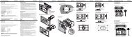
4.1. Aufbau der <strong>CLS</strong>-Geräte 4.1. Design and structure of <strong>CLS</strong> devices<br />
<strong>CLS</strong> 12 Ah<br />
<strong>CLS</strong> <strong>24</strong> Ah<br />
Kabeleinführung / Cable inlet<br />
Kabeleinführung / Cable inlet<br />
Netz LSA1 LSA2 LSA3 LSA4<br />
PE L N N L N L N L N L<br />
R T G IBa IBp IBp<br />
+<strong>24</strong>V<br />
T<br />
SL FS +<strong>24</strong>V Opt.<br />
– + – + – + Stoer<br />
Betr.<br />
Bat.-B.<br />
SK1<br />
- +<br />
SK2<br />
- +<br />
SK3<br />
- +<br />
SK4<br />
- +<br />
Klemmen / Terminals<br />
Netz LSA1 LSA2 LSA3 LSA4<br />
PE L N N L N L N L N L<br />
R T G IBa IBp IBp<br />
+<strong>24</strong>V<br />
T<br />
SL FS +<strong>24</strong>V Opt.<br />
– + – + – + Stoer<br />
Betr.<br />
Bat.-B.<br />
SK1<br />
- +<br />
SK2<br />
- +<br />
SK3<br />
- +<br />
SK4<br />
- +<br />
Steuerteil / Controller<br />
INOTEC<br />
Ein/On Ein/On Ein/On Ein/On<br />
INOTEC<br />
Ein/On<br />
Ein/On<br />
Ein/On<br />
Ein/On<br />
OK<br />
Störung Störung Störung Störung<br />
Failure Failure Failure Failure<br />
SK 1 SK 2 SK 3 SK 4<br />
Batteriesicherung / Battery fuse<br />
OK<br />
Störung Störung Störung Störung<br />
Failure Failure Failure Failure<br />
SK 1 SK 2 SK 3 SK 4<br />
ESC<br />
ESC<br />
Wandler / Inverter<br />
Batteriefach / Battery case<br />
8
Netz LSA1 LSA2 LSA3 LSA4<br />
PE L N N L N L N L N L<br />
Betrieb<br />
Operation<br />
Batt.-Betrieb<br />
Bat.-Operation<br />
Störung<br />
Failure<br />
Lade Störung<br />
Charge failure<br />
Netz<br />
PE L<br />
Betrieb<br />
Operation<br />
Störung<br />
Failure<br />
N<br />
Batt.-Betrieb<br />
Bat.-Operation<br />
Lade Störung<br />
Charge failure<br />
LSA1<br />
N L<br />
LSA2<br />
N L<br />
LSA3<br />
N L<br />
LSA4<br />
N L<br />
R T G IBa IBp IBp<br />
+<strong>24</strong>V<br />
1 2 3 4 5 6 7 8 9 10 11 12 13 14 15 16 17 18 19 20<br />
1 2 3 4 5 6 7 8 9 10 11 12 13 14 15 16 17 18 19 20<br />
T<br />
FS +<strong>24</strong>V<br />
– – + +<br />
Ein/On<br />
Störung<br />
Failure<br />
R T G IBa IBp IBp<br />
FS +<strong>24</strong>V Betr.<br />
+<strong>24</strong>V<br />
– – + + Stoer Bat.-B.<br />
T<br />
Ein/On<br />
Stoer<br />
Ein/On<br />
Störung<br />
Failure<br />
Ein/On<br />
Störung Störung<br />
Failure Failure<br />
Betr.<br />
Bat.-B.<br />
Ein/On<br />
Störung<br />
Failure<br />
SK1<br />
- +<br />
Ein/On<br />
Störung<br />
Failure<br />
SK1 SK2<br />
- + - +<br />
SK2<br />
- +<br />
SK3<br />
- +<br />
SK4<br />
- +<br />
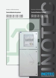
<strong>CLS</strong> <strong>24</strong>/<strong>SV</strong> Montage- und Betriebsanleitung<br />
<strong>CLS</strong> <strong>24</strong>/<strong>SV</strong> Mounting and Operating Instructions<br />
<strong>CLS</strong> <strong>Power</strong> <strong>24</strong> Ah / 48 Ah<br />
Kabeleinführung / Cable inlet<br />
SL<br />
+<br />
–<br />
Opt.<br />
Klemmen / Terminals<br />
Steuerteil / Controller<br />
INOTEC<br />
OK<br />
SK 1 SK 2 SK 3 SK 4<br />
Batteriesicherung / Battery fuse<br />
ESC<br />
Wandler / Inverter<br />
Batteriefach / Battery case<br />
<strong>CLS</strong> <strong>24</strong> - <strong>7Ah</strong><br />
Kabeleinführung / Cable inlet<br />
SL<br />
+<br />
–<br />
Opt.<br />
Klemmen / Terminals<br />
Steuerteil / Controller<br />
INOTEC<br />
OK<br />
SK 1 SK 2<br />
ESC<br />
Batteriesicherung / Battery fuse<br />
Wandler / Inverter<br />
Batteriefach / Battery case<br />
9
<strong>CLS</strong> <strong>24</strong>/<strong>SV</strong> Montage- und Betriebsanleitung<br />
5. Technische Daten<br />
5.1 <strong>CLS</strong> <strong>24</strong> - <strong>7Ah</strong><br />
Anschlussspannung: 230V AC +/- 10%<br />
Klemmenzuleitung: 4 mm²<br />
Ausgangsspannung: <strong>24</strong>V DC +/- 20%<br />
Klemmenabgänge: 4 mm²<br />
Zul. Umgebungstemp.: -5°C bis +25°C<br />
Schutzklasse:<br />
I<br />
Schutzart: IP 20<br />
<strong>CLS</strong> <strong>24</strong>/<strong>SV</strong> Mounting and Operating Instructions<br />
5. Technical data<br />
5.1 <strong>CLS</strong> <strong>24</strong> - <strong>7Ah</strong><br />
Connection voltage: 230V AC +/- 10%<br />
Terminal mains supply: 4 mm²<br />
Output voltage: <strong>24</strong>V DC +/- 20%<br />
Terminal outgoing circuits: 4 mm²<br />
Amb. temp. range:<br />
-5°C to +25°C<br />
Protection class:<br />
I<br />
Protection category: IP 20<br />
Endstromkreise:<br />
Geräuschpegel:<br />
2 Stück<br />
0 dB<br />
Final circuits: x 2<br />
Noise level:<br />
0 dB<br />
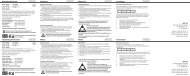
Abmessungen: 345 x <strong>24</strong>5 x 112<br />
Gewicht:<br />
9,6 kg<br />
Batterie:<br />
<strong>24</strong>V / 7,2Ah<br />
Batteriestrom: 1h: 2,7A<br />
3h: 1,7A<br />
Dimensions: 345 x <strong>24</strong>5 x 112<br />
Weight:<br />
9,6 kg<br />
Battery:<br />
<strong>24</strong>V / 7,2Ah<br />
Battery power: 1h: 2,7A<br />
3h: 1,7A<br />
Maßbild<br />
Dimensioned drawing:<br />
343<br />
290<br />
ø4,5<br />
9,5<br />
190<br />
<strong>24</strong>5<br />
112<br />
10
<strong>CLS</strong> <strong>24</strong>/<strong>SV</strong> Montage- und Betriebsanleitung<br />
5.2 <strong>CLS</strong><br />
Anschlussspannung: 230V AC +/- 10%<br />
Klemmenzuleitung: 4 mm²<br />
Ausgangsspannung: <strong>24</strong>V DC +/- 20%<br />
Klemmenabgänge: 4 mm²<br />
Zul. Umgebungstemp.: -5°C bis +25°C<br />
Schutzklasse:<br />
I<br />
Schutzart: IP 20<br />
Endstromkreise:<br />
Max. Belastung:<br />
Geräuschpegel:<br />
4 Stück<br />
3A je Endstromkreis<br />
ca. 40 dB<br />
12 Ah-Anlage <strong>24</strong> Ah-Anlage<br />
Abmessungen: 470 x 253 x 120 630 x 253 x 120<br />
Gewicht: 15 kg 25,7 kg<br />
Batterie: <strong>24</strong>V / 12Ah <strong>24</strong>V / <strong>24</strong>Ah<br />
Batteriestrom: 1h: 6,6A<br />
3h: 2,9A<br />
8h: 1,3A<br />
1h: 6,6A<br />
3h: 5,8A<br />
8h: 2,6A<br />
<strong>CLS</strong> <strong>24</strong>/<strong>SV</strong> Mounting and Operating Instructions<br />
5.2 <strong>CLS</strong><br />
Connection voltage: 230V AC +/- 10%<br />
Terminal mains supply: 4 mm²<br />
Output voltage: <strong>24</strong>V DC +/- 20%<br />
Terminal outgoing<br />
circuits:<br />
4 mm²<br />
Amb. temp. range: -5°C to +25°C<br />
Protection class: I<br />
Protection category: IP 20<br />
Final circuits: x 4<br />
Max. load:<br />
3A per final circuit<br />
Noise level:<br />
approx. 40 dB<br />
12 Ah system <strong>24</strong> Ah system<br />
Dimensions: 470 x 253 x 120 630 x 253 x 120<br />
Weight: 15 kg 25.7 kg<br />
Battery: <strong>24</strong>V / 12Ah <strong>24</strong>V / <strong>24</strong>Ah<br />
Battery power: 1h: 6.6A<br />
3h: 2.9A<br />
8h: 1.3A<br />
1h: 6.6A<br />
3h: 5.8A<br />
8h: 2.6A<br />
Maßbild:<br />
Dimensioned drawing:<br />
210<br />
12 Ah <strong>24</strong> Ah<br />
ø6<br />
ø6<br />
253<br />
380<br />
40<br />
466<br />
116,5<br />
85 220 280<br />
630<br />
210<br />
253<br />
120<br />
11
<strong>CLS</strong> <strong>24</strong>/<strong>SV</strong> Montage- und Betriebsanleitung<br />
5.3 <strong>CLS</strong> <strong>Power</strong><br />
Anschlussspannung: 230V AC +/- 10%<br />
Klemmenzuleitung: 4 mm²<br />
Ausgangsspannung: <strong>24</strong>V DC +/- 20%<br />
Klemmenabgänge: 4 mm²<br />
Zul. Umgebungstemp.: -5°C bis +25°C<br />
Schutzklasse:<br />
I<br />
Schutzart: IP 20<br />
Endstromkreise:<br />
Max. Belastung:<br />
Geräuschpegel:<br />
4 Stück<br />
3A je Endstromkreis<br />
ca. 35 dB<br />
<strong>24</strong> Ah-Anlage 48 Ah-Anlage<br />
Abmessungen: 800 x 400 x 170 800 x 400 x 170<br />
Gewicht: 37,5 kg 56,5 kg<br />
Batterie: <strong>24</strong>V / <strong>24</strong>Ah <strong>24</strong>V / 48Ah<br />
Batteriestrom:<br />
Maßbild:<br />
1h: 12A<br />
3 h: 5,8A<br />
8h: 2,6A<br />
1h: 12A<br />
3h: 11,6A<br />
8h: 5,2A<br />
<strong>CLS</strong> <strong>24</strong>/<strong>SV</strong> Mounting and Operating Instructions<br />
5.3 <strong>CLS</strong> <strong>Power</strong><br />
Connection voltage: 230V AC +/- 10%<br />
Terminal mains supply: 4 mm²<br />
Output voltage: <strong>24</strong>V DC +/- 20%<br />
Terminal outgoing<br />
circuits:<br />
4 mm²<br />
Amb. temp. range: -5°C to +25°C<br />
Protection class: I<br />
Protection category: IP 20<br />
Final circuits: x 4<br />
Max. load:<br />
3A per final circuit<br />
Noise level:<br />
approx. 35 dB<br />
<strong>24</strong> Ah system 48 Ah system<br />
Dimensions: 800 x 400 x 170 800 x 400 x 170<br />
Weight: 37.5 kg 56.5 kg<br />
Battery: <strong>24</strong>V / <strong>24</strong>Ah <strong>24</strong>V / 48Ah<br />
Battery power:<br />
Dimensioned drawing:<br />
1h: 12A<br />
3h: 5.8A<br />
8h: 2.6A<br />
1h: 12A<br />
3h: 11.6A<br />
8h:5.2A<br />
800<br />
400 170<br />
6. Montage<br />
Bei der Montage des Gerätes ist auf ausreichende<br />
Tragfähigkeit der entsprechenden Montagewand<br />
sowie auf geeignetes Montagematerial (Dübel) zu<br />
achten.<br />
Das Notlichtversorgungsgerät <strong>CLS</strong> wird mit eingebauten<br />
Batterien geliefert.<br />
Das Notlichtversorgungsgerät <strong>CLS</strong> <strong>Power</strong> wird ohne eingebaute<br />
Batterien geliefert.<br />
6. Mounting<br />
When mounting the device, make sure that the<br />
supporting wall is strong enough to support<br />
the load and that suitable mounting materials<br />
(dowels) are used.<br />
The emergency lighting device <strong>CLS</strong> is supplied with batteries<br />
installed.<br />
The emergency lighting device <strong>CLS</strong> <strong>Power</strong> is supplied<br />
without installed batteries.<br />
12
<strong>CLS</strong> <strong>24</strong>/<strong>SV</strong> Montage- und Betriebsanleitung<br />
6.1. Gerät<br />
<strong>CLS</strong><br />
Nach dem Auspacken entfernen Sie im<br />
liegenden Zustand die vordere Schraube<br />
am Gehäuse. Jetzt kann die Haube des<br />
Gehäuses abgenommen werden. Die<br />
angeschlossene Erdungsleitung ist steckbar<br />
auf der Gehäuserückwand befestigt.<br />
Um den Bedienschutz der Tasten zu lösen,<br />
entfernen Sie die Schraube oberhalb des<br />
Displays und schieben den Bedienschutz<br />
nach oben.<br />
<strong>CLS</strong> <strong>24</strong>/<strong>SV</strong> Mounting and Operating Instructions<br />
6.1. <strong>Device</strong><br />
<strong>CLS</strong><br />
After unpacking the box, lay the device<br />
down and remove the screw at the front<br />
side of the casing. You will now be able<br />
to remove the front part of the casing.<br />
Attach the connected earth wire by plugging<br />
it into the rear wall of the casing.<br />
To release the protection of the operating<br />
keys, remove the screw above the display<br />
and slide the protection upwards.<br />
<strong>CLS</strong> <strong>Power</strong><br />
Öffnen Sie die Fronttür mit beiligendem<br />
Schlüssel. Zur besseren Belüftung<br />
wird der Schrank mit den beigelegten<br />
Wandbefestigungslaschen an der Wand<br />
befestigt.<br />
4x<br />
<strong>CLS</strong> <strong>Power</strong><br />
Open the front door using the key supplied.<br />
For a better ventilation use the<br />
enclosed plates for attaching the cabinet<br />
to the wall.<br />
6.2. Batterie<br />
Bitte überprüfen Sie die gelieferten Batterien auf<br />
mechanische Beschädigungen und reklamieren diese<br />
umgehend!<br />
Nach der Montage des Gerätes ist zunächst die Batteriesicherung<br />
zu entfernen.<br />
Anschließend sind die Batterieblöcke mit den ab Werk<br />
einseitig aufgesteckten Verbindungsleitungen zu<br />
verbinden.<br />
<strong>7Ah</strong>-Anlage – 1 Verbindungsleitung<br />
12Ah-Anlage – 1 Verbindungsleitung<br />
<strong>24</strong>Ah-Anlage – 2 Verbindungsleitungen<br />
<strong>CLS</strong> <strong>Power</strong><br />
<strong>24</strong>Ah-Anlage – 1 Verbindungsleitung<br />
48Ah-Anlage – 2 Verbindungsleitungen<br />
Im Wandschrank mit 4 Batterien<br />
sind jeweils 4 Abstandshalter<br />
auf der Oberseite der unteren<br />
Batterien zu befestigen.<br />
1.<br />
8x<br />
6.2. Battery<br />
Please check the batteries supplied for signs of<br />
mechanical damage. Any damage should be reported<br />
immediately.<br />
After mounting the device, remove the battery fuse<br />
before carrying out further steps.<br />
Then connect the battery cells to the connection wires<br />
attached on one side at the factory.<br />
<strong>7Ah</strong> system – 1connection wire<br />
12Ah system – 1 connection wire<br />
<strong>24</strong>Ah system – 2 connection wires<br />
<strong>CLS</strong> <strong>Power</strong><br />
<strong>24</strong>Ah system – 1 connection wire<br />
48Ah system – 2 connection wires<br />
INOTEC<br />
Sicherheitstechnik GmbH<br />
4 spaces have to be mounted on<br />
the top of the lower batteries if 4<br />
batteries are installed in the steel<br />
cabinet.<br />
2.<br />
13
<strong>CLS</strong> <strong>24</strong>/<strong>SV</strong> Montage- und Betriebsanleitung<br />
6.3. Elektrischer Anschluss<br />
Die Verkabelung erfolgt bei der <strong>CLS</strong> und <strong>CLS</strong> <strong>Power</strong> über<br />
die oberen Kabeleinführungen.<br />
Im Aufputzgehäuse der <strong>CLS</strong> ist auch eine rückseitige<br />
Kabeleinführung möglich. Dazu ist das vorgestanzte<br />
Blech in der Gehäuserückwand<br />
herauszubrechen.<br />
<strong>CLS</strong> <strong>24</strong>/<strong>SV</strong> Mounting and Operating Instructions<br />
6.3. Electrical connection<br />
The cabelling for the <strong>CLS</strong> and <strong>CLS</strong> <strong>Power</strong> is via the upper<br />
cable inlets.<br />
A rear side cable inlet is possible for the surfacemounted<br />
housing. Therefore the pre-stamped<br />
steel metal at the rear has to be breaked out.<br />
Netzanschluss<br />
Mains connection<br />
Lichtschalterabfrage<br />
Light sequence switching<br />
Lichtschalterabfrage<br />
Light sequence switching<br />
Lichtschalterabfrage<br />
Light sequence switching<br />
Lichtschalterabfrage<br />
Light sequence switching<br />
<strong>CLS</strong> MTB<br />
Externe Komponenten<br />
External components<br />
<strong>CLS</strong> Dimmer<br />
Ohne Funktion<br />
Not in use<br />
DPÜ<br />
Three-phase-monitor<br />
Meldetableau<br />
Mimic panel<br />
Leuchte 1 ... 20<br />
Luminaries 1…20<br />
Leuchte 1 ... 20<br />
Luminaries 1…20<br />
Leuchte 1 ... 20<br />
Luminaries 1…20<br />
Leuchte 1 ... 20<br />
Luminaries 1…20<br />
Netz<br />
PE L N<br />
LSA1<br />
N L<br />
LSA2<br />
N L<br />
LSA3<br />
N L<br />
LSA4<br />
N L<br />
R T G IBa IBp IBp SL FS +<strong>24</strong>V Opt.<br />
+<strong>24</strong>V<br />
– + – + – + Stoer<br />
T<br />
Betr.<br />
Bat.-B.<br />
SK1<br />
- +<br />
- +<br />
SK2<br />
- +<br />
- +<br />
SK3<br />
- +<br />
- +<br />
SK4<br />
- +<br />
- +<br />
InoWeb<br />
INOTEC<br />
Ein/On<br />
Ein/On<br />
Ein/On<br />
Ein/On<br />
Betrieb<br />
Operation<br />
Batt.-Betrieb<br />
Bat.-Operation<br />
Störung<br />
Failure<br />
OK<br />
Störung<br />
Failure<br />
Störung<br />
Failure<br />
Störung<br />
Failure<br />
Störung<br />
Failure<br />
SK 1 SK 2 SK 3 SK 4<br />
Lade Störung<br />
Charge failure<br />
1 2 3 4 5 6 7 8 9 10 11 12 13 14 15 16 17 18 19 20<br />
ESC<br />
14<br />
6.3.1. Netzanschluss<br />
Anschluss der Spannungsversorgung 230V AC an die<br />
Klemmen L, N, PE.<br />
6.3.2. Endstromkreise<br />
Das <strong>CLS</strong>-System besitzt 4 Endstromkreise (2 Endstromkreise<br />
bei <strong>CLS</strong>-<strong>7Ah</strong>) zur Überwachung von je 20 Leuchtenadressen.<br />
Die Endstromkreise können jeweils mit bis<br />
zu max. 3A belastet werden und sind mit 5A abgesichert.<br />
Dabei ist aber auf die Gesamtbelastung des ganzen Systems<br />
zu achten. 5. Technische Daten - Seite 10<br />
Der Einsatz von Kleinspannung (SELV) zur Versorgung<br />
der Notbeleuchtung vereinfacht die Verkabelung und<br />
eine PE-Ader entfällt. Bitte beachten Sie dazu die Angaben<br />
zur Leitungslänge im Anhang C. Leitungslängen<br />
- Seite 55<br />
Über die Klemmen + und -, die pro Endstromkreis<br />
doppelt ausgeführt sind, werden die Leuchten angeschlossen.<br />
Jede Leuchte besitzt eine eindeutige ID, die<br />
dann bei der Programmierung einer lokalen Adresse im<br />
Stromkreis zugeordnet werden muss. 8.3.3. Leuchten<br />
programmieren - Seite 29<br />
Bei der De-/Montage der Leuchten ist darauf<br />
zu achten, dass die IDs auf Gehäuse und Modul<br />
übereinstimmen!<br />
Im Fall der Nachinstallation ist darauf zu achten, dass<br />
jede Leuchten-ID pro Stromkreis nur einmal an der <strong>CLS</strong><br />
angeschlossen wird!<br />
Max. Leitungslänge Endstromkreis Anhang C. Leitungslängen<br />
- Seite 55<br />
6.3.1. Mains connection<br />
Connect the 230V AC voltage supply to terminals L,<br />
N and PE.<br />
6.3.2. Final circuits<br />
The <strong>CLS</strong> system has 4 final circuits (2 final circuits at <strong>CLS</strong>-<br />
<strong>7Ah</strong>) to each monitor 20 luminaire addresses. The final<br />
circuits can each carry a load of max. 3A with a 5A fuse.<br />
Please make sure the total load on the entire system is<br />
not exceeded. 5. Technical data - page 10<br />
Using low voltage (SELV) to supply the emergency lighting<br />
simplifies cabling and eliminates the need for a PE<br />
conductor. Please observe the wire lengths specified in<br />
Appendix C. Wire lengths - Seite 55<br />
The luminaires are connected at terminals + and -, of<br />
which there are 2 per final circuit. Each luminaire has a<br />
unique ID which you must then assign to a local address<br />
on the circuit when you program it. 8.3.3. Programming<br />
luminaires - page 29<br />
When (un)installing the luminaires, make sure<br />
the IDs on the casing and the module match.<br />
In the event of replacement installation, make sure an<br />
identical luminaire ID is not connected more than once<br />
to a circuit of a <strong>CLS</strong>.<br />
Max. wire length of final circuits Appendix C. Wire<br />
lengths - Seite 55
<strong>CLS</strong> <strong>24</strong>/<strong>SV</strong> Montage- und Betriebsanleitung<br />
Anschlussbeispiel L-JET<br />
<strong>CLS</strong> <strong>24</strong>/<strong>SV</strong> Mounting and Operating Instructions<br />
Connection example L-JET<br />
Leuchten-ID<br />
Luminaire ID<br />
INOTEC<br />
L-JET<br />
12738<br />
860 02 1<br />
3<br />
7<br />
ta: 50°C/Un:DC <strong>24</strong>V±20%<br />
Eingang<br />
IBp IBp<br />
SL FS +<strong>24</strong>V Opt.<br />
– + – + – + Stoer<br />
Betr.<br />
Bat.-B.<br />
SK1<br />
- +<br />
- +<br />
SK2<br />
- +<br />
- +<br />
SK3<br />
- +<br />
- +<br />
SK4<br />
- +<br />
- +<br />
6.3.3. Lichtschalterabfrage<br />
Sollen Leuchten der Allgemeinbeleuchtung und Sicherheitsleuchten<br />
gemeinsam geschaltet werden, so kann<br />
unten stehende Schaltung angewendet werden. Die Eingänge<br />
sind für 230V ausgelegt. Dabei können jeder einzelnen<br />
Leuchte bis zu zwei Schaltungseingänge zugeordnet<br />
werden. Näheres zur Programmierung und<br />
Zuweisung finden Sie in 8.3.3. Programmierung<br />
Leuchten - Seite 25. Die Versorgung der Sicherheitsleuchten<br />
im Netzbetrieb erfolgt weiterhin durch das <strong>CLS</strong><br />
<strong>24</strong>-System.<br />
6.3.3. Light sequence switching<br />
If you want to switch general and safety luminaires<br />
on together, refer to the connection diagram below. The<br />
inputs are designed for 230V. You can assign each luminaire<br />
up to 2 switch inputs. For more information on programming<br />
and assignment, see 8.3.3. Programming<br />
luminaires - page 25. The <strong>CLS</strong> <strong>24</strong> system continues to supply<br />
safety luminaires from the <strong>CLS</strong> mains supply.<br />
PE<br />
N<br />
L<br />
Allgemeinbeleuchtung<br />
General lighting<br />
PE<br />
N<br />
L<br />
PE<br />
N<br />
L<br />
Allgemeinbeleuchtung<br />
General lighting<br />
PE<br />
N<br />
L<br />
Allgemeinbeleuchtung<br />
General lighting<br />
Allgemeinbeleuchtung<br />
General lighting<br />
Netz<br />
PE L N<br />
LSA1<br />
N L<br />
LSA2<br />
N L<br />
LSA3<br />
N L<br />
LSA4<br />
N L<br />
R<br />
15
gem.<br />
VDE<br />
0108<br />
gem.<br />
VDE<br />
0108<br />
gem.<br />
VDE<br />
0108<br />
<strong>CLS</strong> <strong>24</strong>/<strong>SV</strong> Montage- und Betriebsanleitung<br />
6.3.4. <strong>24</strong>V-Stromschleife<br />
Um bei Netzausfall in einer Unterverteilung die Sicherheitsleuchten<br />
einzuschalten, sind die Klemmen SL+/<br />
SL- an den Schließer der Dreiphasenüberwachung<br />
anzuschließen. Bei Ausfall wird die <strong>24</strong>V-Stromschleife<br />
unterbrochen und alle Leuchten der Sicherheitsbeleuchtung<br />
schalten in den Notlichtbetrieb. Bei Überwachung<br />
von mehreren Unterverteilern sind die Kontakte für die<br />
Stromschleife in Reihe zu schalten.<br />
Werksseitig sind die Klemmen mit einer Drahtbrücke<br />
verbunden.<br />
<strong>CLS</strong> <strong>24</strong>/<strong>SV</strong> Mounting and Operating Instructions<br />
6.3.4. <strong>24</strong>V current loop<br />
To switch on all connected luminaires in case of a subdb<br />
failure, the terminals SL+ / SL- at the <strong>CLS</strong> have to be<br />
connected to the NO contact at the related DPÜ (three<br />
phase monitor).In case of a power failure at a monitored<br />
sub-db, the <strong>24</strong>V current-loop (SL+ / SL-) will be opened<br />
and all luminaires connected to the <strong>CLS</strong> system are<br />
switching on.To monitor more than one sub-db the NO<br />
contacts at the DPÜs have to be connected in series.<br />
Factory set the SL+ / SL- terminals at the <strong>CLS</strong> system are<br />
connected with a wire strap.<br />
Anschluss bei Überwachung mit dreiphasigem Netz<br />
Supply monitoring in three-phase installation.<br />
Anschluss bei Überwachung mit einphasigem Netz<br />
Supply monitoring in single-phase installation.<br />
Allgemeinbeleuchtung Allgemeinbeleuchtung Allgemeinbeleuchtung<br />
General lighting General lighting General lighting<br />
L1<br />
L2<br />
L3<br />
N<br />
PE<br />
L1<br />
L2<br />
L3<br />
N<br />
PE<br />
L1<br />
N<br />
PE<br />
L3<br />
L2<br />
L1<br />
N<br />
L1<br />
DPÜ<br />
L2<br />
L3<br />
L2<br />
L1<br />
N<br />
L1<br />
DPÜ<br />
L2<br />
L3<br />
L2<br />
L1<br />
N<br />
L1<br />
DPÜ<br />
L2<br />
L3<br />
INOTEC<br />
12<br />
14 11<br />
UVA 1 UVA 2 UVA 3<br />
sub db 1<br />
sub db 2<br />
sub db 3<br />
L3<br />
INOTEC<br />
12<br />
14 11<br />
L3<br />
INOTEC<br />
12<br />
14 11<br />
IBp IBp SL FS +<strong>24</strong>V Opt.<br />
– + – + – + Stoer<br />
Betr.<br />
Bat.-B.<br />
SK1<br />
- +<br />
- +<br />
SK2<br />
- +<br />
- +<br />
SK3<br />
- +<br />
- +<br />
SK4<br />
- +<br />
- +<br />
Die <strong>24</strong>V-Stromschleife kann durch eine Schleifenüberwachung<br />
auf Kurzschluss und Unterbrechung überwacht<br />
werden. Hierzu wird eine Zenerabschlussklemme<br />
in die jeweilige Schleife geschaltet.<br />
Wir empfehlen nach Überprüfung, der Stromschleife,<br />
diese bis zum Ende der Bauarbeiten diese<br />
wieder zu brücken. So wird das Einschalten der<br />
Anlage verhindert, wenn baubedingt eine Sicherung<br />
abgeschaltet wird.<br />
Beside the monitoring for open circuit the <strong>24</strong>V currentloop<br />
can be monitored for short circuit in addition.<br />
Therefor a Zener diode has to be connected to terminate<br />
the related monitoring loop.<br />
To avoid accidental activation, due to power shut<br />
down during construction work, it‘s recommended<br />
to re-insert the wire strap at the SL+ / SL- terminals<br />
(after testing) until end of construction.<br />
16
gem.<br />
VDE<br />
0108<br />
INOTEC<br />
Betrieb<br />
Operation<br />
Batt.-Betrieb<br />
Bat.-Operation<br />
Störung<br />
OK<br />
Failure<br />
Lade Störung<br />
1 2 3 4 5 6 7 8 9 10 11 12 13 14 15 16 17 18 19 20<br />
Charge failure<br />
ESC<br />
Ein/On Ein/On Ein/On Ein/On<br />
Störung Störung Störung Störung<br />
Failure Failure Failure Failure<br />
SK 1 SK 2 SK 3 SK 4<br />
Betrieb<br />
Operation<br />
Batt.-Betrieb<br />
Bat.-Operation<br />
Störung<br />
Failure<br />
Lade Störung<br />
Charge failure<br />
INOTEC<br />
OK<br />
1 2 3 4 5 6 7 8 9 10 11 12 13 14 15 16 17 18 19 20<br />
ESC<br />
Ein/On Ein/On Ein/On Ein/On<br />
Störung Störung Störung Störung<br />
Failure Failure Failure Failure<br />
SK 1 SK 2 SK 3 SK 4<br />
gem.<br />
VDE<br />
0108<br />
Betrieb<br />
Operation<br />
Batt.-Betrieb<br />
Bat.-Operation<br />
Störung<br />
Failure<br />
Lade Störung<br />
Charge failure<br />
INOTEC<br />
OK<br />
1 2 3 4 5 6 7 8 9 10 11 12 13 14 15 16 17 18 19 20<br />
ESC<br />
Ein/On Ein/On Ein/On Ein/On<br />
Störung Störung Störung Störung<br />
Failure Failure Failure Failure<br />
SK 1 SK 2 SK 3 SK 4<br />
<strong>CLS</strong> <strong>24</strong>/<strong>SV</strong> Montage- und Betriebsanleitung<br />
Bei der Stromschleife muss die Zenerabschlussklemme<br />
am letzten Dreiphasenüberwachungsmodul<br />
in Reihe zum Schaltkontakt eingebaut<br />
werden.<br />
<strong>CLS</strong> <strong>24</strong>/<strong>SV</strong> Mounting and Operating Instructions<br />
With the current loop, the zener terminal must be<br />
fitted on the last three-phase monitoring module<br />
in series to the switching contact.<br />
Allgemeinbeleuchtung Allgemeinbeleuchtung Allgemeinbeleuchtung<br />
General lighting General lighting General lighting<br />
L1<br />
L2<br />
L3<br />
N<br />
PE<br />
L1<br />
L2<br />
L3<br />
N<br />
PE<br />
L1<br />
N<br />
PE<br />
L3<br />
L2<br />
L1<br />
N<br />
L1<br />
DPÜ<br />
L2<br />
L3<br />
INOTEC<br />
12<br />
14 11<br />
UVA 1 UVA 2 UVA 3<br />
sub db 1<br />
sub db 2<br />
sub db 3<br />
L3<br />
L2<br />
L1<br />
N<br />
L1<br />
DPÜ<br />
L2<br />
L3<br />
INOTEC<br />
12<br />
14 11<br />
L3<br />
L2<br />
L1<br />
N<br />
L1<br />
DPÜ<br />
L2<br />
L3<br />
INOTEC<br />
12<br />
14 11<br />
Letzte DPÜ<br />
Zenerabschluss<br />
Last DPÜ<br />
Zener diode termination<br />
IBp IBp SL FS +<strong>24</strong>V Opt.<br />
– + – + – + Stoer<br />
Betr.<br />
Bat.-B.<br />
SK1<br />
- +<br />
- +<br />
SK2<br />
- +<br />
- +<br />
SK3<br />
- +<br />
- +<br />
SK4<br />
- +<br />
- +<br />
Besteht die Anforderung, dass weitere Geräte bei<br />
Netzausfall einer Unterverteilung mit einschalten,<br />
kann dies wie folgt realisiert werden. Dazu ist der<br />
optionale Meldekontakt auf die Stromschleife des folgenden<br />
Gerätes zu verdrahten.<br />
Zur Überwachung der Stromschleife auf Kurzschluß und<br />
Unterbrechung können optional Zenerabschlußklemmen<br />
eingestzt werden.<br />
If additional devices need to be switched on in the<br />
event of a power failure to a sub-distribution<br />
board, this can be realised as follows. The optional<br />
signalling contact must be wired to the current loop of<br />
the subsequent device.<br />
Optionally a Zener diode can be used to monitor the <strong>24</strong>V<br />
current loop for open- or short cicuit.<br />
Unterverteilung Unterverteilung Unterverteilung<br />
Sub-db Sub-db Sub-db<br />
L1<br />
L2<br />
L3<br />
N<br />
PE<br />
L1<br />
L2<br />
L3<br />
N<br />
PE<br />
L1<br />
L2<br />
L3<br />
N<br />
PE<br />
Unterverteilung<br />
Sub-db<br />
L1<br />
L2<br />
L3<br />
N<br />
PE<br />
Letzte DPÜ<br />
Zenerabschluss<br />
Last DPÜ<br />
Zener diode termination<br />
optional<br />
DPÜ 3PO DPÜ 3PO DPÜ 3PO<br />
DPÜ 3PO<br />
U<<br />
U<<br />
U<<br />
U<<br />
Allgemeinbeleuchtung Allgemeinbeleuchtung Allgemeinbeleuchtung<br />
General lighting General lighting General lighting<br />
Allgemeinbeleuchtung<br />
General lighting<br />
optional optional optional<br />
SL+ SL-<br />
Optionaler<br />
Kontakt<br />
Optional<br />
contact<br />
SL+ SL-<br />
Optionaler<br />
Kontakt<br />
Optional<br />
contact<br />
SL+ SL-<br />
Optionaler<br />
Kontakt<br />
Optional<br />
contact<br />
<strong>CLS</strong> <strong>CLS</strong> <strong>CLS</strong> <strong>CLS</strong><br />
SL+ SL-<br />
Optionaler<br />
Kontakt<br />
Optional<br />
contact<br />
Der optionale Kontakt ist als Öffner mit Meldung<br />
Netzausfall UV und Netzausfall HV zu programmieren <br />
8.3.1.3. Relais Programmierung - Seite 26<br />
The optional contact has to be programmed as NCcontact<br />
for the signal sub-db failure and mains<br />
failure. 8.3.1.3. Relay programming - page 26<br />
17
Störung<br />
Failure<br />
Batt.-Betrieb<br />
Bat.-Operation<br />
Betrieb<br />
Operation<br />
Betrieb<br />
Operation<br />
Batt.-Betrieb<br />
Bat.-Operation<br />
Störung<br />
OK<br />
Failure<br />
Lade Störung<br />
1 2 3 4 5 6 7 8 9 10 11 12 13 14 15 16 17 18 19 20<br />
Charge failure<br />
ESC<br />
Betrieb<br />
Operation<br />
Batt.-Betrieb<br />
Bat.-Operation<br />
Störung<br />
OK<br />
Failure<br />
Lade Störung<br />
1 2 3 4 5 6 7 8 9 10 11 12 13 14 15 16 17 18 19 20<br />
Charge failure<br />
ESC<br />
Ein/On Ein/On Ein/On Ein/On<br />
Störung Störung Störung Störung<br />
Failure Failure Failure Failure<br />
SK 1 SK 2 SK 3 SK 4<br />
Ein/On Ein/On Ein/On Ein/On<br />
Störung Störung Störung Störung<br />
Failure Failure Failure Failure<br />
SK 1 SK 2 SK 3 SK 4<br />
Betrieb<br />
Operation<br />
Batt.-Betrieb<br />
Bat.-Operation<br />
Störung<br />
OK<br />
Failure<br />
Lade Störung<br />
1 2 3 4 5 6 7 8 9 10 11 12 13 14 15 16 17 18 19 20<br />
Charge failure<br />
ESC<br />
Betrieb<br />
Operation<br />
Batt.-Betrieb<br />
Bat.-Operation<br />
Störung<br />
OK<br />
Failure<br />
Lade Störung<br />
1 2 3 4 5 6 7 8 9 10 11 12 13 14 15 16 17 18 19 20<br />
Charge failure<br />
ESC<br />
Ein/On Ein/On Ein/On Ein/On<br />
Störung Störung Störung Störung<br />
Failure Failure Failure Failure<br />
SK 1 SK 2 SK 3 SK 4<br />
Ein/On Ein/On Ein/On Ein/On<br />
Störung Störung Störung Störung<br />
Failure Failure Failure Failure<br />
SK 1 SK 2 SK 3 SK 4<br />
Betrieb<br />
Operation<br />
Batt.-Betrieb<br />
Bat.-Operation<br />
Störung<br />
OK<br />
Failure<br />
Lade Störung<br />
1 2 3 4 5 6 7 8 9 10 11 12 13 14 15 16 17 18 19 20<br />
Charge failure<br />
ESC<br />
Betrieb<br />
Operation<br />
Batt.-Betrieb<br />
Bat.-Operation<br />
Störung<br />
OK<br />
Failure<br />
Lade Störung<br />
1 2 3 4 5 6 7 8 9 10 11 12 13 14 15 16 17 18 19 20<br />
Charge failure<br />
ESC<br />
Ein/On Ein/On Ein/On Ein/On<br />
Störung Störung Störung Störung<br />
Failure Failure Failure Failure<br />
SK 1 SK 2 SK 3 SK 4<br />
Ein/On Ein/On Ein/On Ein/On<br />
Störung Störung Störung Störung<br />
Failure Failure Failure Failure<br />
SK 1 SK 2 SK 3 SK 4<br />
<strong>CLS</strong> <strong>24</strong>/<strong>SV</strong> Montage- und Betriebsanleitung<br />
6.3.5. <strong>CLS</strong> Meldetableau<br />
Mehrere <strong>CLS</strong>-Geräte können über den 3-adrigen RTG-<br />
BUS auf ein zentrales Meldetableau aufgeschaltet werden.<br />
Dieses unterstützt zwei Stränge mit jeweils max.<br />
8 Geräten je Strang. Über das Meldetableau können<br />
detaillierte Statusinformationen bis zur Leuchtenstörung<br />
im Klartext abgerufen, zentrale Test gestartet und alle<br />
Systeme blockiert werden.<br />
Max. Leitungslänge bei<br />
3x1,5mm² 500m<br />
Ein gleichzeitiger Betrieb von RTG-Bus und Ino-<br />
Web-Modul ist nicht möglich!<br />
Meldetableau mit <strong>CLS</strong>-Geräten!<br />
<strong>CLS</strong> <strong>24</strong>/<strong>SV</strong> Mounting and Operating Instructions<br />
6.3.5. <strong>CLS</strong> mimic panel<br />
You can connect several <strong>CLS</strong> devices to a central mimic<br />
panel using the triple conductor RTG-BUS. This supports<br />
two data-lines each with up to 8 devices. You can use<br />
the mimic panel to view detailed status information on<br />
luminaire failures in plain text, run central tests and block<br />
all systems.<br />
Max. wire length for<br />
3x1.5mm² 500m<br />
It is not possible to run the RTG Bus and InoWeb<br />
module at the same time.<br />
Mimic panel with <strong>CLS</strong> devices<br />
RTG<br />
max. 500m<br />
INOTEC<br />
INOTEC<br />
INOTEC<br />
3<br />
3<br />
max. 500m<br />
RTG<br />
<strong>CLS</strong> 1<br />
<strong>CLS</strong> 2 <strong>CLS</strong> 8<br />
INOTEC<br />
INOTEC<br />
INOTEC<br />
<strong>CLS</strong> 1 <strong>CLS</strong> 2 <strong>CLS</strong> 8<br />
18
<strong>CLS</strong> <strong>24</strong>/<strong>SV</strong> Montage- und Betriebsanleitung<br />
6.3.6. Meldetableau<br />
Wird ein externes Fernmeldetableau eingesetzt, so ist<br />
dieses nach der Beschreibung des Fernmeldetableaus<br />
an die Klemmen anzuschließen.<br />
Die Kontakte des Fernschalters sind werksseitig gebrückt.<br />
Über diesen ist es möglich, die Dauerlichtleuchten des<br />
Systems zu blockieren.<br />
<strong>CLS</strong> <strong>24</strong>/<strong>SV</strong> Mounting and Operating Instructions<br />
6.3.6. Mimic panel<br />
If you are implementing an external remote mimic panel,<br />
connect this to the terminals as described in the remote<br />
mimic panel documentation.<br />
The remote switch contacts are bridged at the factory.<br />
This enables you to block the system's maintained<br />
lighting.<br />
Relais Betrieb<br />
Relay operation<br />
Relais Störung<br />
Relay failure<br />
Relais Batteriebetrieb<br />
Relay battery operation<br />
Optionaler Relaiskontakt<br />
Op. relay contact<br />
Betrieb<br />
Operation<br />
Störung<br />
Sum-failure<br />
X<br />
Batt.-Betrieb<br />
Battery operation<br />
X<br />
Keine Spannung<br />
No voltage<br />
Potentialfreie Meldekontakte, max.<strong>24</strong>V, 1A DC.<br />
Voltfree signaling contacts, max. <strong>24</strong>V, 1A DC.<br />
Meldetableau Notlicht<br />
Betrieb<br />
Batt.-Betrieb<br />
Fernschalter<br />
Ein<br />
INOTEC<br />
MTB<br />
Störung<br />
Aus<br />
+<strong>24</strong>V<br />
T<br />
1<br />
3 5<br />
FS+ FS-<br />
IBp IBp<br />
SL FS +<strong>24</strong>V Opt.<br />
– + – + – + Stoer<br />
Betr.<br />
Bat.-B.<br />
SK1<br />
- +<br />
- +<br />
SK2<br />
- +<br />
- +<br />
An den <strong>24</strong>V - Ausgangsklemmen kann eine Spannung<br />
von 18V-29,5V anliegen.<br />
A voltage of 18V-29,5V can be at the <strong>24</strong>V outgoing<br />
terminals<br />
Meldetableau Notlicht<br />
Betrieb<br />
Batt.-Betrieb<br />
Fernschalter<br />
Ein<br />
INOTEC<br />
MTB<br />
Störung<br />
Aus<br />
+<strong>24</strong>V<br />
T<br />
1 3 5 FS+ FS-<br />
SL FS +<strong>24</strong>V Opt.<br />
– + – + – + Stoer<br />
Betr.<br />
Bat.-B.<br />
SK1<br />
- +<br />
- +<br />
SK2<br />
- +<br />
- +<br />
SK3<br />
- +<br />
- +<br />
SK4<br />
- +<br />
- +<br />
SL FS +<strong>24</strong>V Opt.<br />
– + – + – + Stoer<br />
Betr.<br />
Bat.-B.<br />
SK1<br />
- +<br />
- +<br />
SK2<br />
- +<br />
- +<br />
SK3<br />
- +<br />
- +<br />
SK4<br />
- +<br />
- +<br />
19
INOTEC<br />
Betrieb<br />
Operation<br />
Batt.-Betrieb<br />
Bat.-Operation<br />
Störung<br />
OK<br />
Failure<br />
Lade Störung<br />
1 2 3 4 5 6 7 8 9 10 11 12 13 14 15 16 17 18 19 20<br />
Charge failure<br />
ESC<br />
Ein/On Ein/On Ein/On Ein/On<br />
Störung Störung Störung Störung<br />
Failure Failure Failure Failure<br />
SK 1 SK 2 SK 3 SK 4<br />
<strong>CLS</strong> <strong>24</strong>/<strong>SV</strong> Montage- und Betriebsanleitung<br />
6.3.7. InoWeb<br />
Ist das optionale InoWeb-Modul eingebaut, so ist an dieses<br />
Modul das Netzwerkkabel anzuschließen.<br />
Über das InoWeb-Modul kann der Zustand des <strong>CLS</strong>-<br />
Gerätes über das Netzwerk abgefragt werden.<br />
Im Webbrowser wird der Zustand zu jeder überwachten<br />
Leuchte grafisch dargestellt.<br />
weitere Informationen 10. INOWEB - Seite 38<br />
Ein gleichzeitiger Betrieb von RTG-Bus und Ino-<br />
Web-Modul ist nicht möglich!<br />
<strong>CLS</strong> <strong>24</strong>/<strong>SV</strong> Mounting and Operating Instructions<br />
6.3.7. InoWeb<br />
If the optional InoWeb module is installed, connect the<br />
network cable to it.<br />
You can obtain status information regarding the <strong>CLS</strong><br />
device using the InoWeb module.<br />
The status of every monitored luminaire is graphically<br />
displayed in the web browser.<br />
For more information 10. INOWEB - page 38<br />
It is not possible to run the RTG Bus and InoWeb<br />
module at the same time.<br />
ON<br />
OFF<br />
2 1<br />
Reset <strong>CLS</strong><br />
RS 232<br />
ON<br />
OFF<br />
2 1<br />
max. 100m<br />
max. 100m<br />
max. 100m<br />
HUB / Switch<br />
max. 100m<br />
max. 100m<br />
max. 100m<br />
max. 100m<br />
HUB / Switch<br />
max. 100m<br />
InoWeb<br />
Control<br />
<strong>CLS</strong> InoWeb<br />
<strong>CLS</strong> InoWeb<br />
<strong>CLS</strong> InoWeb<br />
Verkabelung Ethernet (min. CAT 5)<br />
Wiring<br />
<strong>CLS</strong> InoWeb<br />
<strong>CLS</strong> InoWeb<br />
<strong>CLS</strong> InoWeb<br />
6.3.8. Zentrales Dimmen<br />
Mit dem optionalen <strong>CLS</strong>-<br />
Dimmer Modul können<br />
entsprechend programmierte<br />
Leuchten in den<br />
Stromkreisen über<br />
• Taster am <strong>CLS</strong> Dimmer<br />
Modul<br />
• Einen extern<br />
angeschlossenen Taster<br />
• eine 0-10V<br />
Steuerspannung<br />
zentral gedimmt werden,<br />
regelbar in 10%-Stufen<br />
von 0% (Leuchte aus) bis<br />
zu 100% (Leuchte ein).<br />
Damit sind die Leuchten<br />
der Notbeleuchtung mit<br />
denen der Allgemeinbeleuchtung<br />
gemeinsam<br />
zu dimmen (z.B. über ein<br />
EIB-Modul). Im Notbetrieb<br />
schalten die Leuchten<br />
automatisch auf 100%.<br />
R T G IBa IBp IBp SL FS +<strong>24</strong>V Opt.<br />
+<strong>24</strong>V – + – + – + Stoer<br />
T<br />
oder / or<br />
Potentiometer<br />
0-10V<br />
+ 0-10V - 0-10V<br />
<strong>CLS</strong>-Dimmer<br />
INOTEC<br />
850 013<br />
Bus<br />
+<strong>24</strong>V<br />
Taster ext.<br />
0 - 10V<br />
Taster<br />
Ta: -15 bis 40°C<br />
EMC: gem. EN 55015<br />
T<br />
T<br />
6.3.8. Central dimming<br />
With the optional <strong>CLS</strong> dimmer module<br />
you can dim specifically programmed<br />
luminaires in the circuits,<br />
by using<br />
• the pushbuttons on the <strong>CLS</strong> dimmer<br />
module<br />
• via an externally connected<br />
pushbutton<br />
• a 0-10V control voltage,<br />
which you can control in 10% increments<br />
from 0% (luminaires off ) to<br />
100% (luminaires on).<br />
The emergency lighting is dimmed<br />
along with the general lighting (e.g.<br />
using an EIB module). In emergency<br />
mode, the luminaires automatically<br />
switch to 100%.<br />
20
<strong>CLS</strong> <strong>24</strong>/<strong>SV</strong> Montage- und Betriebsanleitung<br />
7. Inbetriebnahme des <strong>CLS</strong>-Gerätes<br />
Vor dem Einschalten der Netzspannung und Einsetzen<br />
der Batteriesicherung sind unbedingt folgende<br />
Prüfungen durchzuführen:<br />
• Prüfung aller Anschlüsse an das Gerät<br />
• Prüfung des Anschlusses der <strong>24</strong>V-Stromschleife (SL+ / SL-)<br />
• Prüfung der korrekten Verbindung der Batterieblöcke<br />
• Vor dem ersten Funktions- bzw. Betriebsdauertest sind<br />
die Batterien im Gerät min. <strong>24</strong> Stunden zu laden<br />
7.1. Ausschalten des <strong>CLS</strong>-Gerätes<br />
Beim Abschalten des <strong>CLS</strong>-Gerätes ist unbedingt folgende<br />
Reihenfolge zu beachten!<br />
1. Anlage Notlicht und Dauerlicht blockieren<br />
2. Batteriesicherung entfernen<br />
3. Netz abschalten<br />
7.2. Einschalten des <strong>CLS</strong>-Gerätes<br />
Beim Einschalten ist diese Reihenfolge zu beachten<br />
1. Netz einschalten<br />
2. Batteriesicherung einsetzen<br />
Das Gerät wird initialisiert und im Display wird Betrieb,<br />
Ladespannung und Ladestrom angezeigt.<br />
Alle zum Betrieb notwendigen Einstellung müssen vorgenommen<br />
werden. 8.3. „Programmierung“ - Seite 25<br />
7.3. Lieferzustand<br />
Steuerteil:<br />
- Passwort: 0000<br />
- Betriebsdauer: 1h<br />
- InoWeb: aktiviert, wenn eingebaut<br />
- SL mit SLÜ: deaktiviert<br />
- FS mit SLÜ: deaktiviert<br />
- Notlichtnachlauf: 0 Minuten<br />
- Handrückschaltung: deaktiviert<br />
Alle Stromkreise sind aktiviert.<br />
<strong>CLS</strong> <strong>24</strong>/<strong>SV</strong> Mounting and Operating Instructions<br />
7. Commissioning the <strong>CLS</strong> device<br />
Before switching on the mains voltage and inserting<br />
the battery fuse, you must carry out the following<br />
tests:<br />
• Test all connections on the device<br />
• Test the connection of the <strong>24</strong>V current loop (SL+ / SL-)<br />
• Check that the battery cells are properly connected<br />
• Before carrying out the initial function or battery<br />
duration test, charge the batteries in the device for<br />
at least <strong>24</strong> hours<br />
7.1. Switching OFF the <strong>CLS</strong> device<br />
When switching off the <strong>CLS</strong> device, you must complete<br />
the following in this order<br />
1. Block the emergency and maintained lighting<br />
2. Remove the battery fuse<br />
3. Switch off the mains supply<br />
7.2. Switching ON the <strong>CLS</strong> device<br />
When switching on the <strong>CLS</strong> device, complete the<br />
following in this order<br />
1. Switch on the mains supply<br />
2. Insert the battery fuse<br />
When the device starts up, the display indicates the operation,<br />
charging voltage and charging current.<br />
You must now make all the settings necessary for use.<br />
8.3. „Programming“ - page 25<br />
7.3. Factory settings<br />
Controller:<br />
- Password: 0000<br />
- Operating time: 1h<br />
- InoWeb: activated, if installed<br />
- SL with monitoring loop function: deactivated<br />
- Remote switch with monitoring<br />
loop function:<br />
deactivated<br />
- <strong>Emergency</strong> lighting delay: 0 minutes<br />
- Manual reset: deactivated<br />
All electric circuits are activated.<br />
21
<strong>CLS</strong> <strong>24</strong>/<strong>SV</strong> Montage- und Betriebsanleitung<br />
8. Bedienung<br />
<strong>CLS</strong> <strong>24</strong>/<strong>SV</strong> Mounting and Operating Instructions<br />
8. Use<br />
INOTEC<br />
INOTEC<br />
F T - ><br />
C L S 2 4 V<br />
B e t r i e b<br />
U = 2 7 . 5 V I = + 0 . 0 A<br />
OK<br />
F T - ><br />
C L S 2 4 V<br />
o p e r a t i o n<br />
U = 2 7 . 5 V I = + 0 . 0 A<br />
OK<br />
1 2 3 4 5 6 7 8 9 10 11 12 13 14 15 16 17 18 19 20<br />
ESC<br />
1 2 3 4 5 6 7 8 9 10 11 12 13 14 15 16 17 18 19 20<br />
ESC<br />
Die Bedienung des <strong>CLS</strong>-Systems erfolgt über 4 Tasten,<br />
die neben dem Display platziert sind. Die oberen beiden<br />
Tasten dienen zur Navigation. „OK“ ist zur Bestätigung<br />
bzw. Anwahl einer Funktion und mit „ESC“ wechselt man<br />
in das vorherige Menü bzw. bricht eine Funktion ab.<br />
Unterhalb des Displays sind Zahlen von 1 bis 20 angebracht,<br />
welche die Stromkreis- bzw. Leuchtenadresse<br />
angeben.<br />
Zielorte werden am Gerät über die PS/2-Tastaturschnittstelle<br />
mit einer herkömmlichen PC-Tastatur eingegeben.<br />
Durch längeres drücken der „ESC“ Taste wird aus<br />
jedem Untermenü in das Hauptmenü zurück<br />
gesprungen.<br />
To operate the <strong>CLS</strong> system, use the 4 buttons positioned<br />
alongside the display. Use the top two buttons to navigate.<br />
Use "OK" to confirm or select a function and "ESC"<br />
to switch back to the previous menu or cancel a function.<br />
Underneath the display are the numbers 1 through 20,<br />
which indicate the electric circuit or luminaire address.<br />
Type in destinations on the device using a regular PC<br />
keyboard connected via the PS/2 keyboard interface.<br />
Press and hold "ESC" to jump back to the main<br />
menu from any submenu.<br />
22
<strong>CLS</strong> <strong>24</strong>/<strong>SV</strong> Montage- und Betriebsanleitung<br />
8.1. Menüstruktur<br />
Das Hauptmenü wird durch drücken der Taste „OK“<br />
aufgerufen.<br />
2. Testmenü<br />
2.1. Funktionstest starten <strong>24</strong><br />
2.2. Betriebsdauertest starten <strong>24</strong><br />
2.3. Funktionstest abbrechen <strong>24</strong><br />
2.5. Automatischer FT <strong>24</strong><br />
2.6 Automatischer BT 25<br />
3. Programmierung<br />
3.1. Geräteeinstellungen 25<br />
3.1.1. InoWeb 25<br />
3.1.2 RTG-Adresse 25<br />
3.1.3. Relais Programmierung 26<br />
Prog. Opt. Relais<br />
Prog. Kontakte<br />
3.1.4. Ext. Komponenten 26<br />
3.1.5. SL mit SLÜ 26<br />
3.1.6. FS mit SLÜ 26<br />
3.1.7. Notlicht Nachlauf 26<br />
3.1.8. Handrückschaltung 27<br />
3.1.9. Zentrales Dimmen 27<br />
3.1.10. Blockieren von … 27<br />
3.1.11. Gerätezielort 27<br />
3.1.12. Zentrales Licht ein 28<br />
3.2. Stromkreise programmieren 28<br />
Stromkr. anmelden<br />
Stromkr. Zielort<br />
3.3. Leuchten programmieren 28<br />
Leuchten anmelden<br />
Adr. zuweisen<br />
Leuchten Konfig.<br />
3.3.4 Zentrales Dimmen (Dim) 30<br />
3.3.5 Leuchten Zielort 30<br />
3.4. Spracheinstellung 30<br />
3.5. Passwort ändern 30<br />
3.6. Uhrzeit & Datum 31<br />
3.7. Blockierung 31<br />
3.8. INOSTICK 31<br />
3.8.1 Konfiguration laden 31<br />
3.8.2. Konfiguration speichern 32<br />
4. Info<br />
4.1. Geräteinformation 33<br />
4.2 Stromkreis- / Leuchteninformationen 33<br />
4.3 Störungsinfo 34<br />
4.3.1 Störung anzeigen 34<br />
4.3.2 Störungen speichern 34<br />
4.4. Prüfbuch 34<br />
4.4.1 Prüfbuch anzeigen 34<br />
4.4.2. Prüfbuch ausgeben 35<br />
4.4.3. Prüfbuch löschen 35<br />
5. Blockierung aufheben 36<br />
<strong>CLS</strong> <strong>24</strong>/<strong>SV</strong> Mounting and Operating Instructions<br />
8.1. Menu structure<br />
Press "OK" to go to the main menu.<br />
2. Test menu<br />
2.1. Running a function test <strong>24</strong><br />
2.2. Running a battery duration test <strong>24</strong><br />
2.3. Canceling a function test <strong>24</strong><br />
2.5. Automatic function test <strong>24</strong><br />
2.6 Automatic battery duration test 25<br />
3. Programming<br />
3.1. <strong>Device</strong> settings 25<br />
3.1.1. InoWeb 25<br />
3.1.2 RTG-Adresse 25<br />
3.1.3. Relay programming 26<br />
Prog. opt. relay<br />
Prog. contacts<br />
3.1.4. External components 26<br />
3.1.5. Current loop, monitoring loop fct. 26<br />
3.1.6. Remote switch, monitoring loop fct. 26<br />
3.1.7. <strong>Emergency</strong> lighting delay 26<br />
3.1.8. Manual reset 27<br />
3.1.9 Central dimming 27<br />
3.1.10. Blocking… 27<br />
3.1.11. <strong>Device</strong> destination 27<br />
3.1.12. Central light on 28<br />
3.2. Programming circuits 28<br />
Registering luminaries<br />
Circuit destination<br />
3.3. Programming luminaries 28<br />
Registering luminaries<br />
Assigning an address<br />
Config.luminaries<br />
3.3.4 Central dimming (Dim) 30<br />
3.3.5 Luminaire destination 30<br />
3.4. Setting the language 30<br />
3.5. Changing your password 30<br />
3.6. Time & date 31<br />
3.7. Blocking 31<br />
3.8. INOSTICK 31<br />
3.8.1 Loading the configuration 31<br />
3.8.2. Saving the configuration 32<br />
4. information<br />
4.1. <strong>Device</strong> information 33<br />
4.2 Circuit/luminaire information 33<br />
4.3 Fault information 34<br />
4.3.1 Displaying the fault 34<br />
4.3.2 Saving faults 34<br />
4.4 Lokbook 34<br />
4.4.1 Displaying the logbook 34<br />
4.4.2. Saving the logbook 35<br />
4.4.3. Deleting the logbook 35<br />
5. Unblock system 36<br />
23
<strong>CLS</strong> <strong>24</strong>/<strong>SV</strong> Montage- und Betriebsanleitung<br />
8.2. „Testmenü“<br />
8.2.1. Funktionstest starten<br />
Im Funktionstestmodus schaltet das Gerät in den Batteriebetrieb<br />
und überprüft die angeschlossenen und<br />
angemeldeten Leuchten auf deren Funktionstüchtigkeit.<br />
Das Ergebnis des Funktionstest wird im Prüfbuch abgespeichert<br />
und bei einer Leuchtenstörung wird diese im<br />
Display angezeigt.<br />
Nach Reparatur einer Leuchte muss ein erneuter<br />
Funktionstest ausgeführt werden, damit die Störung<br />
zurückgesetzt wird.<br />
OK Testmenü Ok FT Start OK<br />
8.2.2. Betriebsdauertest starten<br />
Der Betriebsdauertest schaltet das <strong>CLS</strong>-Gerät in den Batteriebetrieb<br />
und ermittelt die maximale Laufzeit bis zum<br />
Tiefentladeschutz der Batterie.<br />
OK Testmenü OK BT Starten OK<br />
8.2.3. Funktionstest abbrechen<br />
OK Testmenü OK FT abbrechen OK<br />
Über diesen Befehl kann ein gerade laufender Funktionstest<br />
abgebrochen werden.<br />
Über die obere Taste „FT-Stopp“ im Hauptbild kann<br />
ebenfalls ein gerade laufender Funktionstest unterbrochen<br />
werden.<br />
8.2.4. Betriebsdauertest abbrechen<br />
OK Testmenü OK BT abbrechen OK<br />
Ein versehentlich gestarteter Betriebsdauertest kann<br />
im Testmenü über den Befehl „BT abbrechen“ manuell<br />
beendet werden.<br />
8.2.5. Automatischer FT<br />
Ein automatischer Funktionstest wird wie folgt<br />
einprogrammiert:<br />
OK Testmenü Ok automat. FT FT<br />
INOTEC<br />
<strong>CLS</strong> <strong>24</strong>/<strong>SV</strong> Mounting and Operating Instructions<br />
8.2. "Test menu"<br />
8.2.1. Running a function test<br />
In function test mode, the device switches to battery<br />
mode and checks that the connected and registered<br />
luminaires are working accordingly. The results of the<br />
function test are saved in the logbook and are shown<br />
on the display if there is a luminaire failure.<br />
After a luminaire is repaired, carry out a new<br />
function test to resolve the fault.<br />
OK test menu OK FT start OK<br />
8.2.2. Running a battery duration test<br />
The battery duration test switches the <strong>CLS</strong> device into<br />
battery mode and calculates the maximum runtime<br />
until the battery's deep discharge protection comes into<br />
effect.<br />
OK test menu OK start DT OK<br />
8.2.3. Canceling a function test<br />
OK test menu OK cancel FT OK<br />
You can use this command to cancel a running<br />
function test.<br />
You can also use the top button "stop FT" on the<br />
main screen to cancel a running function test.<br />
8.2.4. Canceling a battery duration test<br />
OK test menu OK cancel DT OK<br />
If a battery duration test was started unintentionally, you<br />
can cancel it manually using the "cancel DT" command<br />
from the test menu.<br />
8.2.5. Automatic function test<br />
You can program an automatic function test as follows:<br />
OK test menu OK automat. FT FT<br />
INOTEC<br />
U h r z e i t : 0 6 : 3 0<br />
M D M D F S S<br />
x x<br />
OK<br />
t i m e : 0 6 : 3 0<br />
M T W T F S S<br />
x x<br />
OK<br />
1 2 3 4 5 6 7 8 9 10 11 12 13 14 15 16 17 18 19 20<br />
ESC<br />
1 2 3 4 5 6 7 8 9 10 11 12 13 14 15 16 17 18 19 20<br />
ESC<br />
Über die beiden oberen Tasten wird die Zeit eingestellt,<br />
mit „OK“ wird zur nächsten Stelle gewechselt. Außerdem<br />
kann festgelegt werden, an welchen Wochentagen der<br />
Funktionstest ausgeführt werden soll. Danach startet das<br />
<strong>CLS</strong>-System jede Woche den Funktionstest zum angegebenen<br />
Zeitpunkt.<br />
Use the two top buttons to set the time. Press "OK" to<br />
continue. You can also set the day of the week you want<br />
the function test to run on. The <strong>CLS</strong> system will then<br />
start the function test at the specified time each week.<br />
<strong>24</strong>
<strong>CLS</strong> <strong>24</strong>/<strong>SV</strong> Montage- und Betriebsanleitung<br />
8.2.6 Automatischer BT<br />
Das <strong>CLS</strong>-System kann zu einem festgelegten Zeitpunkt<br />
einen automatischen Betriebsdauertest ausführen. Im<br />
Menü wird die Uhrzeit und das Datum angegeben.<br />
OK Testmenü OK automat. BT OK<br />
INOTEC<br />
U h r z e i t : 2 3 : 0 0<br />
D a t u m : 1 3 . 1 2 . 0 8<br />
OK<br />
<strong>CLS</strong> <strong>24</strong>/<strong>SV</strong> Mounting and Operating Instructions<br />
8.2.6 Automatic battery duration test<br />
You can configure the <strong>CLS</strong> system to carry out an automatic<br />
battery duration test at a specified time. The time<br />
and date appear in the menu.<br />
OK test menu OK automat. DT OK<br />
INOTEC<br />
t i m e : 2 3 : 0 0<br />
d a t e : 1 3 . 1 2 . 0 8<br />
OK<br />
1 2 3 4 5 6 7 8 9 10 11 12 13 14 15 16 17 18 19 20<br />
ESC<br />
1 2 3 4 5 6 7 8 9 10 11 12 13 14 15 16 17 18 19 20<br />
ESC<br />
Der automatische Betriebsdauertest wird jedes Jahr zur<br />
angegebenen Zeit ausgeführt und das Ergebnis im Prüfbuch<br />
gespeichert.<br />
8.3. „Programmierung“<br />
Um die Einstellungen vor unbefugtem Zugriff zu schützen,<br />
ist eine Passwortabfrage eingebaut. Das Passwort<br />
kann in den Geräteeinstellungen individuell gewählt<br />
werden. Werksseitig ist „0000“ als Passwort eingestellt.<br />
8.3.1. Geräteeinstellungen<br />
OK Programmierung OK Geräteprog. OK<br />
INOTEC<br />
The automatic battery duration test is carried out at<br />
the specified time each year and the results are saved<br />
in the logbook.<br />
8.3. "Programming"<br />
To protect your settings from unauthorized access, you<br />
are prompted to enter a password. You can choose an<br />
individual password in the device settings. The default<br />
password is "0000".<br />
8.3.1. <strong>Device</strong> settings<br />
OK program OK program device OK<br />
INOTEC<br />
I n o w e b :<br />
R T G A d r e s s e 1<br />
R e l a i s P r o g .<br />
E x t . K o m p o n e n t e n<br />
OK<br />
I n o w e b :<br />
R T G a d d r e s s 1<br />
v o l t f r e e c o n t a c t<br />
E x t . c o m p o n e n t s<br />
OK<br />
1 2 3 4 5 6 7 8 9 10 11 12 13 14 15 16 17 18 19 20<br />
ESC<br />
1 2 3 4 5 6 7 8 9 10 11 12 13 14 15 16 17 18 19 20<br />
ESC<br />
8.3.1.1. InoWeb<br />
Wenn ein InoWeb-Modul installiert ist, kann dieses hier<br />
aktiviert werden.<br />
8.3.1.2. RTG-Adresse<br />
INOTEC<br />
R T G A d r e s s e : 5<br />
8.3.1.1. InoWeb<br />
If an InoWeb module is installed, you can activate it here.<br />
8.3.1.2. RTG address<br />
INOTEC<br />
R T G a d d r e s s : 5<br />
OK<br />
OK<br />
1 2 3 4 5 6 7 8 9 10 11 12 13 14 15 16 17 18 19 20<br />
ESC<br />
1 2 3 4 5 6 7 8 9 10 11 12 13 14 15 16 17 18 19 20<br />
ESC<br />
Ein gleichzeitiger Betrieb von RTG-BUS und INO-<br />
WEB-Modul ist nicht möglich!<br />
Bei einer zentralen Überwachung des <strong>CLS</strong>-Gerätes über<br />
das Meldetableau wird in diesem Menüpunkt die Geräteadresse<br />
vergeben (0-32). Die Einstellung 0 deaktiviert die<br />
Datenkommunikation für das Meldetableau.<br />
Simultaneous operation of the RTG-BUS and<br />
INOWEB module is not possible!<br />
If the <strong>CLS</strong> device is centrally monitored on the mimic<br />
panel, specify the device address in this menu (0-32).<br />
Entering 0 will deactivate data communication to the<br />
mimic panel.<br />
25
<strong>CLS</strong> <strong>24</strong>/<strong>SV</strong> Montage- und Betriebsanleitung<br />
Für die Überwachung per INOWEB-Modul muss<br />
die Adresse 0 eingestellt werden und die Option<br />
InoWeb aktiviert sein! 8.3.1.1. InoWeb - Seite 25<br />
8.3.1.3. Relais Programmierung<br />
In diesem Menü werden die Einstellungen für die Meldekontakte<br />
vorgenommen.<br />
Unter „Prog. Kontakte“ wird definiert, ob es sich bei diesem<br />
Kontakt um einen Öffner oder<br />
Schließer handelt.<br />
Die Meldungen von drei Relaiskontakten sind fest programmiert,<br />
die Meldung des vierten Relais wird im Menü<br />
„Prog. Opt. Relais“ festgelegt. Es besteht die Möglichkeit<br />
auch mehrere Meldungen auszuwählen, die dann mit<br />
„Oder“ verknüpft werden. INOTEC<br />
<strong>CLS</strong> <strong>24</strong>/<strong>SV</strong> Mounting and Operating Instructions<br />
If the system is monitored using the INOWEB<br />
module, you must enter the address as 0 and<br />
activate the InoWeb option. 8.3.1.1. InoWeb -<br />
page 25<br />
8.3.1.3. Relay programming<br />
Make the signaling contact settings in this menu.<br />
Under "Prog. contacts", define if this contact is a NC-contact<br />
or NO-contact .<br />
The signals of 3 relay contacts are pre-programmed but<br />
you can set the signal for the 4th relay in the menu "Prog.<br />
opt. relay". You also have the option to select multiple<br />
signals, which you can then combine with "or".<br />
INOTEC<br />
N e t z a u s f a l l H V<br />
N e t z a u s f a l l U V<br />
S t a r k l a d u n g<br />
L a d e s t ö r u n g<br />
OK<br />
c o n t a c t a c t i v e a t H V<br />
m a i n s f a i l u r e U V<br />
b o o s t c h a r g i n g<br />
c h a r g i n g f a i l u r e<br />
OK<br />
1 2 3 4 5 6 7 8 9 10 11 12 13 14 15 16 17 18 19 20<br />
ESC<br />
1 2 3 4 5 6 7 8 9 10 11 12 13 14 15 16 17 18 19 20<br />
ESC<br />
- Netzausfall HV<br />
- Netzausfall UV<br />
- Starkladung<br />
- Ladestörung<br />
- Gerät blockiert<br />
- Leuchtenstörung<br />
- Mains failure<br />
- Sub-db failure<br />
- Boost charging<br />
- Charging failure<br />
- <strong>Device</strong> blocked<br />
- Luminaire failure<br />
8.3.1.4. Ext. Komponenten<br />
8.3.1.4. External components<br />
Zum jetzigen Zeitpunkt werden noch keine externen<br />
Komponenten unterstützt.<br />
8.3.1.5. SL mit SLÜ<br />
Überwachung der Stromschleife mittels Zener-Diode<br />
aktivieren. Diese Option ist nur zu aktivieren, wenn auch<br />
eine Zener-Diode installiert ist. 6.3.4. <strong>24</strong>V-Stromschleife<br />
- Seite 16<br />
8.3.1.6. FS mit SLÜ<br />
Überwachung des Fernschalters mittels Zener-Diode<br />
aktivieren. Diese Option ist nur zu aktivieren, wenn auch<br />
eine Zener-Diode installiert ist. 6.3.4. <strong>24</strong>V-Stromschleife<br />
- Seite 16<br />
8.3.1.7. Notlicht Nachlauf<br />
INOTEC<br />
At the time of writing, external components are not<br />
supported.<br />
8.3.1.5. Current loop with monitoring loop function<br />
Activate monitoring of the current loop using a Zener<br />
diode. Only activate this option if a Zener diode is installed.<br />
6.3.4. <strong>24</strong>V current loop - page 16<br />
8.3.1.6. Remote switch with monitoring loop function<br />
Activate monitoring of the remote switch using a Zener<br />
diode. Only activate this option if a Zener diode is installed.<br />
6.3.4. <strong>24</strong>V current loop - page 16<br />
8.3.1.7. <strong>Emergency</strong> lighting delay<br />
INOTEC<br />
E i n s t e l l e n d e r N o t -<br />
l i c h t N a c h l a u f Z e i t :<br />
1 0 m i n<br />
OK<br />
S e t d e l a y t i m e o n<br />
m a i n s r e t u r n :<br />
1 0 m i n<br />
OK<br />
1 2 3 4 5 6 7 8 9 10 11 12 13 14 15 16 17 18 19 20<br />
ESC<br />
1 2 3 4 5 6 7 8 9 10 11 12 13 14 15 16 17 18 19 20<br />
ESC<br />
26
<strong>CLS</strong> <strong>24</strong>/<strong>SV</strong> Montage- und Betriebsanleitung<br />
Bei Rückkehr der Netzversorgung bleiben alle Leuchten<br />
für die angegebene Zeit noch eingeschaltet. Die Zeit ist<br />
zwischen 1 – 15 Minuten frei wählbar. 0 Minuten deaktiviert<br />
die Einstellung.<br />
8.3.1.8. Handrückschaltung<br />
Bei aktivierter Handrückschaltung erfolgt nach einem<br />
Netzausfall die Rückschaltung erst durch eine manuelle<br />
Bestätigung am Gerät oder per Fernüberwachung. Dies<br />
gewährleistet, dass das Notlicht so lange eingeschaltet<br />
bleibt, bis die Allgemeinbeleuchtung wieder eingeschaltet<br />
ist und eine manuelle Bestätigung erfolgt.<br />
8.3.1.9. Zentrales Dimmen<br />
OK Programmierung OK Geräteprog. OK <br />
Zentrales Dimmen<br />
Diese Option aktiviert die Möglichkeit der zentralen<br />
Dimmung von Leuchten in den Endstromkreisen. Weitere<br />
Informationen zu dieser Funktion 6.3.8. Zentrales Dimmen<br />
- Seite 20<br />
8.3.1.10. Blockieren von …<br />
OK Programmierung OK Geräteprog. OK <br />
Blockieren von … OK<br />
INOTEC<br />
<strong>CLS</strong> <strong>24</strong>/<strong>SV</strong> Mounting and Operating Instructions<br />
When the power returns, all luminaires continue to<br />
stay on for the time specified. You can select any time<br />
between 1-15 minutes. Setting the time to 0 minutes<br />
disables the setting.<br />
8.3.1.8. Manual reset<br />
If the manual reset setting is enabled, when the power<br />
fails you can only perform a reset by manually confirming<br />
it on the device or by remote monitoring. This<br />
ensures that the emergency lighting stays on until the<br />
general lighting is switched back on and manual confirmation<br />
took place.<br />
8.3.1.9. Central dimming<br />
OK program OK programm device OK <br />
central dimming<br />
This option activates the option to centrally dim luminaires<br />
in the final circuits. For more information on this<br />
function, see 6.3.8. Central dimming - page 20<br />
8.3.1.10. Blocking…<br />
OK program OK programm device OK <br />
blocking setup OK<br />
INOTEC<br />
B l o c k i e r e n v o n :<br />
N o t l i c h t<br />
D a u e r l i c h t<br />
<br />
<br />
OK<br />
b l o c k i n g :<br />
e m e r g e n c y l i g h t<br />
m a i n s l i g h t<br />
<br />
<br />
OK<br />
1 2 3 4 5 6 7 8 9 10 11 12 13 14 15 16 17 18 19 20<br />
ESC<br />
1 2 3 4 5 6 7 8 9 10 11 12 13 14 15 16 17 18 19 20<br />
ESC<br />
Festlegung welche Betriebsarten über 8.3.7. Blockierung<br />
- Seite 31<br />
Fernschalter oder per Fernüberwachung / MTB blockiert<br />
werden:<br />
• Dauerlicht (DL)<br />
• Dauerlicht (DL) und Notlicht (NL)<br />
Bei Aktivierung der Option Dauerlicht und Notlicht<br />
bleibt im blockierten Gerätezustand das Notlicht<br />
während eines Netzausfalls aus!<br />
8.3.1.11. Gerätezielort<br />
OK Programmierung OK Geräteprog. OK <br />
Zielort<br />
INOTEC<br />
Specify which types of operation are blocked with<br />
8.3.7. Blocking - page 31<br />
remote switches or by remote monitoring / MTB:<br />
• Mains lighting<br />
• Mains lighting and emergency lighting<br />
If the mains lighting and emergency lighting<br />
option is activated when the device is blocked,<br />
the emergency lighting will remain off in the<br />
event of a power failure.<br />
8.3.1.11. <strong>Device</strong> destination<br />
OK program OK programm device OK <br />
destination<br />
INOTEC<br />
Z i e l o r t :<br />
E i n g a n g s b e r e i c h<br />
OK<br />
d e s t i n a t i o n :<br />
E n t r y<br />
OK<br />
1 2 3 4 5 6 7 8 9 10 11 12 13 14 15 16 17 18 19 20<br />
ESC<br />
1 2 3 4 5 6 7 8 9 10 11 12 13 14 15 16 17 18 19 20<br />
ESC<br />
27
<strong>CLS</strong> <strong>24</strong>/<strong>SV</strong> Montage- und Betriebsanleitung<br />
In dem Gerät kann ein Zielort mit maximal 20 Zeichen<br />
hinterlegt werden. Dieser wird auch in einer angeschlossenen<br />
Visualisierung angezeigt.<br />
8.3.1.12. Zentrales Licht ein<br />
OK Programmierung OK Geräteprog. OK zentral.<br />
Licht Ein<br />
INOTEC<br />
<strong>CLS</strong> <strong>24</strong>/<strong>SV</strong> Mounting and Operating Instructions<br />
You can store a (max.) 20-character destination on the<br />
device. This is also displayed on a connected visualization<br />
device.<br />
8.3.1.12. Central light on<br />
OK program OK programm device OK <br />
central light on<br />
INOTEC<br />
Z e n t r a l e s D i m m e n<br />
b l o c k i e r e n v o n …<br />
G e r ä t e Z i e l o r t<br />
> z e n t r . L i c h t E i n <br />
OK<br />
C e n t r a l d i m m i n g<br />
b l o c k i n g s e t u p<br />
d e v . D e s t i n a t i o n<br />
> c e n t r a l l i g h t o n <br />
OK<br />
1 2 3 4 5 6 7 8 9 10 11 12 13 14 15 16 17 18 19 20<br />
ESC<br />
1 2 3 4 5 6 7 8 9 10 11 12 13 14 15 16 17 18 19 20<br />
ESC<br />
Ist das Gerät an ein <strong>CLS</strong>-MTB angeschlossen und die<br />
Option aktiviert, schaltet es bei Erkennung von Netzausfall<br />
UV oder Netzausfall HV eines anderen <strong>CLS</strong>-Gerätes<br />
am <strong>CLS</strong>-MTB oder Erkennung von Netzausfall UV des<br />
<strong>CLS</strong>-MTBs mit ein. Weitere Informationen finden Sie<br />
hierzu in der Bedienungsanleitung des <strong>CLS</strong>-MTB.<br />
Die Umschaltzeiten der gültigen Vorschriften sind<br />
zu beachten.<br />
If the <strong>CLS</strong> system is connected to a <strong>CLS</strong>-MTB and the<br />
function „central light on“ is activated, all connected luminaires<br />
will switch on in the following cases:<br />
- mains failure / sub-db failure at any <strong>CLS</strong> system connected<br />
to the same MTB;<br />
- sub-db failure detected by the SL+ / SL- contacts at the<br />
<strong>CLS</strong>-MTB.<br />
For further details please refer to the operating manual of<br />
<strong>CLS</strong>-MTB.<br />
The switch over time of the current regulations<br />
have to be observed!<br />
8.3.2. Stromkreise programmieren<br />
OK Programmierung OK Stromkreisprog. OK<br />
INOTEC<br />
S t r o m k r . a n m e l d e n<br />
S t r o m k r . Z i e l o r t e<br />
8.3.2. Programming circuits<br />
OK program OK prog. circuits OK<br />
INOTEC<br />
a c t i v a t e c i r c u i t<br />
c i r c u i t d e s t i n a t i o n<br />
OK<br />
OK<br />
1 2 3 4 5 6 7 8 9 10 11 12 13 14 15 16 17 18 19 20<br />
ESC<br />
1 2 3 4 5 6 7 8 9 10 11 12 13 14 15 16 17 18 19 20<br />
ESC<br />
8.3.2.1. Stromkreise anmelden<br />
8.3.2.1. Activate circuits<br />
Im Menü „Stromkr. anmelden“ müssen die benutzen<br />
Stromkreise angemeldet werden. Mit den Navigationstasten<br />
wählen Sie den entsprechenden Stromkreis aus,<br />
der dann mit „OK“ an- bzw. abgemeldet werden kann.<br />
INOTEC<br />
In the "Activate circuits" menu, you must register the<br />
circuits in use. Use the navigation buttons to select the<br />
relevant circuit and then register/deregister it by pressing<br />
"OK".<br />
INOTEC<br />
S t r o m k r e i s : 1<br />
Z u m a n u n d a b m e l d e n<br />
O K d r ü c k e n<br />
X X X<br />
OK<br />
c i r c u i t : 1<br />
p r e s s O K t o<br />
d e - o r a c t i v a t e<br />
X X X<br />
OK<br />
1 2 3 4 5 6 7 8 9 10 11 12 13 14 15 16 17 18 19 20<br />
ESC<br />
1 2 3 4 5 6 7 8 9 10 11 12 13 14 15 16 17 18 19 20<br />
ESC<br />
Störungen in abgemeldeten Stromkreisen werden<br />
nicht angezeigt!<br />
Faults in deregistered circuits are not displayed.<br />
28
<strong>CLS</strong> <strong>24</strong>/<strong>SV</strong> Montage- und Betriebsanleitung<br />
8.3.2.2. Stromkreis Zielorte<br />
Zu jedem Endstromkreis kann noch ein Zielorttext eingegeben<br />
werden. Dazu wählen Sie den Punkt „Stromkr.<br />
Zielorte“. Über die Navigationstasten den entsprechenden<br />
Stromkreis auswählen und den Zielort an der angeschlossenen<br />
PC-Tastatur eingeben.<br />
INOTEC<br />
<strong>CLS</strong> <strong>24</strong>/<strong>SV</strong> Mounting and Operating Instructions<br />
8.3.2.2. Circuit destinations<br />
You can add a destination description for every final circuit.<br />
To do this, select "Circuit destinations". Use the navigation<br />
buttons to select the relevant circuit and type in<br />
the destination using a connected PC keyboard.<br />
INOTEC<br />
S t r o m k r e i s : 1<br />
Z i e l o r t :<br />
V e r w a l t u n g 1 . O G<br />
X X X<br />
OK<br />
c i r c u i t : 1<br />
d e s t i n a t i o n :<br />
M a n a g m e n t 1 . O G<br />
X X X<br />
OK<br />
1 2 3 4 5 6 7 8 9 10 11 12 13 14 15 16 17 18 19 20<br />
ESC<br />
1 2 3 4 5 6 7 8 9 10 11 12 13 14 15 16 17 18 19 20<br />
ESC<br />
Mit Enter wird der Zielort gespeichert und automatisch<br />
zum nächsten Stromkreis gewechselt.<br />
Während der Zielorteingabe schalten alle angeschlossenen<br />
Leuchten auf Dauerlicht.<br />
8.3.3. Leuchten programmieren<br />
OK Programmierung OK Leuchtenprog. OK<br />
Jede Leuchte für das <strong>CLS</strong>-System hat eine Leuchten ID,<br />
welcher einer Leuchtenadresse im Stromkreis zugeordnet<br />
werden muss. Dazu ist die Leuchtenadresse<br />
im Stromkreis wie folgt anzumelden:<br />
Leuchten anmelden OK<br />
INOTEC<br />
Press "Enter" to save the destination and switch<br />
automatically to the next circuit.<br />
During destination description input all connected<br />
luminaires switch to maintained light.<br />
8.3.3. Programming luminaires<br />
OK program OK prog. luminaires OK<br />
Every <strong>CLS</strong> system luminaire has a luminaire ID (address),<br />
which you must assign to a luminaire address in the circuit.<br />
In doing so, you must register the luminaire address<br />
in the circuit as follows:<br />
Activate luminaires OK<br />
INOTEC<br />
L e u c h t e : 1 S K : 1<br />
Z u m a n u n d a b m e l d e n<br />
O K d r ü c k e n<br />
X X X X X X X X X X X X X X X X X<br />
OK<br />
l u m . : 1 C I : 1<br />
p r e s s O K t o<br />
d e - o r a c t i v a t e<br />
X X X X X X X X X X X X X X X X X<br />
OK<br />
1 2 3 4 5 6 7 8 9 10 11 12 13 14 15 16 17 18 19 20<br />
ESC<br />
1 2 3 4 5 6 7 8 9 10 11 12 13 14 15 16 17 18 19 20<br />
ESC<br />
Mit den Navigationstasten wird die Leuchtenadresse<br />
ausgewählt, über OK wird diese an- bzw. abgemeldet. Nur<br />
angemeldete Adressen können programmiert werden<br />
und melden Störungen.<br />
Die Zuordnung zwischen Leuchtenadresse und Leuchten<br />
ID ist im Menü „Adr. Zuweisen“ zu programmieren.<br />
INOTEC<br />
Use the navigation buttons to select the luminaire<br />
address and press "OK" to register/deregister it. You can<br />
only program registered addresses and only these will<br />
signal faults.<br />
Program the luminaire address/luminaire ID assignment<br />
under "Assigning an address".<br />
INOTEC<br />
L e u c h t e : 1 S K : 1<br />
I n d i v i d u e l l e A d r e s s e<br />
1 8 4 2 0<br />
X X X X X X X X X X X X X X X X X<br />
OK<br />
l u m . : 1 C I : 1<br />
i n d i v i d u a l a d d r e s s<br />
1 8 4 2 0<br />
X X X X X X X X X X X X X X X X X<br />
OK<br />
1 2 3 4 5 6 7 8 9 10 11 12 13 14 15 16 17 18 19 20<br />
ESC<br />
1 2 3 4 5 6 7 8 9 10 11 12 13 14 15 16 17 18 19 20<br />
ESC<br />
Über die Navigationstasten wird die Ziffer eingestellt,<br />
durch Drücken von „OK“ gelangen Sie zur nächsten Stelle.<br />
Das Menü wird über „ESC“ verlassen.<br />
Nach dieser Zuordnung wird die Leuchte im Menü<br />
„Leuchten Konfig.“ entsprechend konfiguriert. Dabei<br />
können für jede Leuchte individuell zwischen drei Schaltungsarten<br />
gewählt werden:<br />
Use the navigation buttons to enter the number, then<br />
press "OK" to continue. Press "ESC" to exit the menu.<br />
After this assignment, configure the luminaires accordingly<br />
under the "Config. luminaires" menu. You can<br />
choose between 3 operating modes for each luminaire:<br />
29
<strong>CLS</strong> <strong>24</strong>/<strong>SV</strong> Montage- und Betriebsanleitung<br />
<strong>CLS</strong> <strong>24</strong>/<strong>SV</strong> Mounting and Operating Instructions<br />
8.3.3.1. Bereitschaftslicht (BL)<br />
Im Normalbetrieb ist die Leuchte ausgeschaltet. Bei<br />
Netzausfall UV bzw. Netzausfall HV wird die Leuchte<br />
eingeschaltet.<br />
8.3.3.2. Dauerlicht (DL)<br />
In der Schaltungsart Dauerlicht ist die Leuchte auch im<br />
Normalbetrieb eingeschaltet. Über einen frei wählbaren<br />
Wert kann die Leuchte gedimmt werden. Bei Notbetrieb<br />
schaltet das System automatisch auf 100%. Der<br />
Dimmwert kann über die Navigationstasten eingestellt<br />
werden.<br />
8.3.3.3. Geschaltetes Dauerlicht (gDL)<br />
Hier besteht die Möglichkeit die Leuchte über Schalteingänge<br />
der systeminternen Lichtschalterabfrage zu schalten.<br />
Es können dabei zwei Zuordnungen pro Leuchte<br />
getroffen werden.<br />
INOTEC<br />
8.3.3.1. Non-maintained lighting<br />
The luminaire is turned off in normal operation. In the<br />
event of a sub-db failure or main-db failure the luminaire<br />
is switched on.<br />
8.3.3.2. Maintained lighting<br />
In the maintained light switching mode the luminaire is<br />
switched on even in normal mode. You can dim the luminaire<br />
to any value you choose. In emergency mode the<br />
system automatically switches to 100%. Use the navigation<br />
buttons to set the dimming value.<br />
8.3.3.2. Switched maintained lighting<br />
This gives you the option to switch luminaires via input<br />
switches associated with the in-system light sequence<br />
switching. You can make two assignments per luminaire.<br />
INOTEC<br />
L e u c h t e : 1 S K : 1<br />
S c h a l t u n g s a r t : g D L<br />
1 : K 1 D i m 8 0 i n v : N<br />
2 : K 3 D i m 5 0 i n v : J<br />
OK<br />
l u m . : 1 C I : 1<br />
o p e r a t i o n m o d e : s M L<br />
1 : K 1 D i m 8 0 i n v : Y<br />
2 : K 3 D i m 5 0 i n v : N<br />
OK<br />
1 2 3 4 5 6 7 8 9 10 11 12 13 14 15 16 17 18 19 20<br />
ESC<br />
1 2 3 4 5 6 7 8 9 10 11 12 13 14 15 16 17 18 19 20<br />
ESC<br />
K1-K4 gibt den Kanal für die systeminterne Lichtschalterabfrage<br />
an. Für jede Zuweisung kann ein Dimmwert<br />
angegeben werden, mit dem die Leuchte bei eingeschaltetem<br />
Kanal betrieben werden soll. Über die Option „inv“<br />
wird der Eingang invertiert, die Zuweisung wird bei Öffnung<br />
des Kanals aktiviert.<br />
8.3.3.4 Zentrales Dimmen (Dim)<br />
Leuchten, die auf diese Schaltungsart programmiert<br />
werden, können im Netzbetrieb über das optionale <strong>CLS</strong>-<br />
Dimmer Modul gedimmt werden. 6.3.8 Zentrales Dimmen<br />
- Seite 16<br />
INOTEC<br />
L e u c h t e : 1 S K : 1<br />
S c h a l t u n g s a r t : D I M<br />
OK<br />
K1-K4 specify the channel for the in-system light<br />
sequence switching. Under each assignment you can<br />
specify a dimming value for the luminaires when the<br />
channel is switched on. The "inv" option inverts the<br />
input and the assignment is activated when the channel<br />
is opened.<br />
8.3.3.4 Central dimming (Dim)<br />
You can adjust the light output of luminaires programmed<br />
to this switching mode using the optional<br />
<strong>CLS</strong> dimmer module for the mains supply. 6.3.8 Central<br />
dimming - page 16<br />
INOTEC<br />
l u m . : 1 C I : 1<br />
o p e r a t i o n m o d e : D I M<br />
OK<br />
1 2 3 4 5 6 7 8 9 10 11 12 13 14 15 16 17 18 19 20<br />
ESC<br />
1 2 3 4 5 6 7 8 9 10 11 12 13 14 15 16 17 18 19 20<br />
ESC<br />
8.3.3.5 Leuchten Zielort<br />
8.3.3.5 Luminaire destination<br />
30<br />
Mit einer PC-Tastatur besteht die Möglichkeit im Menü<br />
„Leuchten Zielort“ jeder Leuchte eine bis zu 20 Zeichen<br />
lange Zielortbeschreibung zu geben.<br />
Mit Enter wird der Zielort gespeichert und automatisch<br />
zur nächsten angemeldeten Leuchte des aktiven<br />
Stromkreises gewechselt.<br />
Während der Zielorteingabe schalten alle angeschlossenen<br />
Leuchten auf Dauerlicht.<br />
You can use a PC keyboard to provide a (max.) 20-character<br />
destination description for each luminaire under the<br />
"Luminaire destination" menu.<br />
Press "Enter" to save the destination and automatically<br />
switch to the next registered luminaire in the<br />
active circuit.<br />
During destination description input all connected<br />
luminaires switch to maintained light.
<strong>CLS</strong> <strong>24</strong>/<strong>SV</strong> Montage- und Betriebsanleitung<br />
8.3.4. Spracheinstellung<br />
<strong>CLS</strong> <strong>24</strong>/<strong>SV</strong> Mounting and Operating Instructions<br />
8.3.4. Setting the language<br />
OK Programmierung OK Sprache OK<br />
INOTEC<br />
OK program OK language OK<br />
INOTEC<br />
W ä h l e n S i e e i n e<br />
S p r a c h e :<br />
d e u t s c h<br />
OK<br />
p l e a s e s e l e c t y o u r<br />
l a n g u a g e :<br />
e n g l i s h<br />
OK<br />
1 2 3 4 5 6 7 8 9 10 11 12 13 14 15 16 17 18 19 20<br />
ESC<br />
1 2 3 4 5 6 7 8 9 10 11 12 13 14 15 16 17 18 19 20<br />
ESC<br />
Bei Änderungen der Sprache wird automatisch die<br />
Anzeige im InoWeb-Modul geändert.<br />
8.3.5. Passwort ändern<br />
Changing the language automatically changes the<br />
display in the InoWeb module.<br />
8.3.5. Changing your password<br />
OK Programmierung OK Passwort ändern OK<br />
INOTEC<br />
OK program OK change password OK<br />
INOTEC<br />
G e b e n S i e e i n e n e u e s<br />
P a s s w o r t e i n :<br />
N e u e s P W : * * * *<br />
P W b e s t . : * * * *<br />
OK<br />
p l e a s e e n t e r a n e w<br />
p a s s w o r d :<br />
n e w p a s s w o r d : * * * *<br />
r e p e a t p a s s w o r d : * * * *<br />
OK<br />
1 2 3 4 5 6 7 8 9 10 11 12 13 14 15 16 17 18 19 20<br />
ESC<br />
1 2 3 4 5 6 7 8 9 10 11 12 13 14 15 16 17 18 19 20<br />
ESC<br />
Es kann eine vierstellige Zahlenkombination als Passwort<br />
gewählt werden. Durch erneute Eingabe wird das Passwort<br />
bestätigt.<br />
Werksseitig ist das Passwort auf „0000“ eingestellt.<br />
8.3.6. Uhrzeit & Datum<br />
OK Programmierung OK Uhrzeit & Datum<br />
INOTEC<br />
You can choose a 4-digit number as your password.<br />
Enter it twice to confirm.<br />
The default password is "0000".<br />
8.3.6. Time & date<br />
OK program OK time & date<br />
INOTEC<br />
U h r z e i t : 1 8 : 1 2<br />
D a t u m : 1 5 . 0 1 . 0 8<br />
W o c h e n t a g :<br />
M o<br />
OK<br />
t i m e : 1 8 : 1 2<br />
d a t e : 1 5 . 0 1 . 0 8<br />
w e e k d a y :<br />
M o<br />
OK<br />
1 2 3 4 5 6 7 8 9 10 11 12 13 14 15 16 17 18 19 20<br />
ESC<br />
1 2 3 4 5 6 7 8 9 10 11 12 13 14 15 16 17 18 19 20<br />
ESC<br />
Über die Navigationstasten werden das Datum und die<br />
Uhrzeit der Realtime-Clock eingestellt. „OK“ wechselt zur<br />
nächsten Stelle. Die Einstellung des korrekten Wochentags<br />
ist zur Ausführung des automatischen Funktionstests<br />
notwendig.<br />
8.3.7. Blockierung<br />
OK Programmierung OK Blockierung <br />
OK<br />
Das Gerät blockiert die im Optionsmenü 8.3.1.10.<br />
Blockieren von ... - Seite 23 angegebenen Betriebsarten<br />
(Dauerlichtbetrieb oder Dauer- und Notlichtbetrieb)<br />
Use the navigation buttons to set the date and time of<br />
the realtime clock. Press "OK" to continue. You need to<br />
set the correct day of the week to be able to carry out<br />
automatic function tests.<br />
8.3.7. Blocking<br />
OK program OK block OK<br />
The device blocks the operating modes specified in the<br />
options menu 8.3.1.10. Blocking ... - page 23 (mains<br />
lighting or mains and emergency lighting)<br />
31
<strong>CLS</strong> <strong>24</strong>/<strong>SV</strong> Montage- und Betriebsanleitung<br />
8.3.8. INOSTICK<br />
8.3.8.1 Konfiguration laden<br />
OK Programmierung OK INOSTICK OK <br />
Konfig. laden OK<br />
INOTEC<br />
W ä h l e n S i e e i n e<br />
K o n f i g u r a t i o n s d a t e i :<br />
<strong>CLS</strong> <strong>24</strong>/<strong>SV</strong> Mounting and Operating Instructions<br />
8.3.8. INOSTICK<br />
8.3.8.1 Loading the configuration<br />
OK program OK INOSTICK OK load config.<br />
OK<br />
INOTEC<br />
S e l e c t a<br />
c o n f i g u r a t i o n :<br />
C L S - 0 1<br />
OK<br />
C L S - 0 1<br />
OK<br />
1 2 3 4 5 6 7 8 9 10 11 12 13 14 15 16 17 18 19 20<br />
ESC<br />
1 2 3 4 5 6 7 8 9 10 11 12 13 14 15 16 17 18 19 20<br />
ESC<br />
Mittels des INOSTICKS und der Konfigurator Software<br />
besteht die Möglichkeit das <strong>CLS</strong>-Gerät am PC zu konfigurieren<br />
und diese anschließend zu laden.<br />
Nachdem der INOSTICK mit dem Tastaturanschluss des<br />
<strong>CLS</strong>-Gerätes verbunden wurde und der Befehl „Konfig.<br />
laden“ mit OK ausgewählt wird, ist die entsprechende<br />
Konfigurationsdatei auszuwählen. Bei der Programmierung<br />
werden alle Einstellungen für das Gerät und der<br />
Leuchten vom INOSTICK geladen und im Gerät gespeichert.<br />
Das Einspielen der Konfiguration kann einige<br />
Minuten in Anspruch nehmen, im Display wird der Fortschritt<br />
angezeigt.<br />
INOTEC<br />
L a d e K o n f i g u r a t i o n<br />
K o n f i g . S K : 1 L : 2 0 ü<br />
K o n f i g . S K : 2 L : 2 0 ü<br />
K o n f i g . S K : 3 L : 0 9<br />
1 2 3 4 5 6 7 8 9 10 11 12 13 14 15 16 17 18 19 20<br />
OK<br />
ESC<br />
Das Laden der Konfiguration kann nach dem Start<br />
nicht unterbrochen werden.<br />
Der INOSTICK darf nicht gleichzeitig mit der <strong>CLS</strong><br />
und einem PC verbunden sein.<br />
8.3.8.2. Konfiguration speichern<br />
OK Programmierung OK INOSTICK OK <br />
Konfig. speichern OK<br />
INOTEC<br />
G e b e n S i e e i n e n<br />
D a t e i n a m e n a n :<br />
The INOSTICK and configuration software enables you<br />
to configure the <strong>CLS</strong> device on your PC and then upload<br />
it to the <strong>CLS</strong>.<br />
Connect the INOSTICK to the keyboard connection on<br />
the <strong>CLS</strong> device, press "OK" to select the "Load config."<br />
command, then select the relevant configuration file.<br />
The programming process uploads all settings for the<br />
device and luminaires from the INOSTICK and saves<br />
them on the device. It may take several minutes for the<br />
configuration to be imported — you can check the progress<br />
on the display.<br />
INOTEC<br />
L o a d i n g c o n f i g .<br />
K o n f i g . C I : 1 L : 2 0 ü<br />
K o n f i g . C I : 2 L : 2 0 ü<br />
K o n f i g . C I : 3 L : 0 9<br />
1 2 3 4 5 6 7 8 9 10 11 12 13 14 15 16 17 18 19 20<br />
OK<br />
ESC<br />
You cannot cancel the upload process once it has<br />
started.<br />
Don’t connect the INOSTICK with the <strong>CLS</strong> and a<br />
PC at the same time.<br />
8.3.8.2. Saving the configuration<br />
OK program OK INOSTICK OK save config.<br />
OK<br />
INOTEC<br />
P l e a s e e n t e r a<br />
f i l e n a m e :<br />
C O N F I G 0 1<br />
OK<br />
C O N F I G 0 1<br />
OK<br />
1 2 3 4 5 6 7 8 9 10 11 12 13 14 15 16 17 18 19 20<br />
ESC<br />
1 2 3 4 5 6 7 8 9 10 11 12 13 14 15 16 17 18 19 20<br />
ESC<br />
Zuerst ist der INOSTICK an die Tastaturbuchse des <strong>CLS</strong>-<br />
Gerätes anzuschließen. Es ist ein Dateiname für die Konfigurationsdatei<br />
anzugeben. Mittels der Pfeiltasten kann<br />
das Zeichen gewählt werden, „OK“ springt zur nächsten<br />
Stelle und „ESC“ löscht das Zeichen.<br />
First connect the INOSTICK to the keyboard port on the<br />
<strong>CLS</strong> device. Specify a file name for the configuration file.<br />
Use the arrow buttons to select the symbol, press "OK"<br />
to jump to the next step or "ESC" to delete the symbol.<br />
32<br />
Die Länge des Namens darf 8 Zeichen nicht<br />
überschreiten.<br />
The name must be no longer than 8 characters.
<strong>CLS</strong> <strong>24</strong>/<strong>SV</strong> Montage- und Betriebsanleitung<br />
Falls der Dateiname schon vorhanden ist, so muss ein<br />
anderer angegeben werden. Die Konfiguration wird dann<br />
auf dem INOSTICK gespeichert und kann mit der Konfigurator-Software<br />
angepasst werden.<br />
INOTEC<br />
<strong>CLS</strong> <strong>24</strong>/<strong>SV</strong> Mounting and Operating Instructions<br />
If the file name already exists, choose a different name.<br />
The configuration is then saved on the INOSTICK and<br />
you can modify it using the configuration software.<br />
INOTEC<br />
S p e i c h e r<br />
K o n f i g u r a t i o n<br />
K o n f i g . S K : 1 L : 2 0 ü<br />
K o n f i g . S K : 2 L : 0 7<br />
OK<br />
S a v i n g c o n f i g u r a t i o n<br />
K o n f i g . C I : 1 L : 2 0 ü<br />
K o n f i g . C I : 2 L : 0 7<br />
OK<br />
1 2 3 4 5 6 7 8 9 10 11 12 13 14 15 16 17 18 19 20<br />
ESC<br />
1 2 3 4 5 6 7 8 9 10 11 12 13 14 15 16 17 18 19 20<br />
ESC<br />
8.4. „Informationen“<br />
8.4. "Information"<br />
8.4.1. Geräteinformation<br />
OK Info OK Geräteinfo OK<br />
8.4.1. <strong>Device</strong> information<br />
OK info OK device info OK<br />
Im Menu Gerätinformation werden alle Geräterelevanten<br />
Informationen angezeigt. Dazu gehören:<br />
- Inoweb<br />
- RTG Adresse<br />
- Optionaler Kontakt<br />
- Notlicht Nachlaufzeit<br />
- SL mit SLÜ<br />
- FS mit SLÜ<br />
- Handrückschaltung<br />
- Zentrales Dimmen<br />
- Version<br />
- BT-Zeit<br />
- Meldekontakte<br />
- Seriennummer<br />
8.4.2 Stromkreis- / Leuchteninformationen<br />
OK Info OK SK/ Leuchten Info OK<br />
INOTEC<br />
The "device information" menu displays all information<br />
relevant to the device. This includes:<br />
- Inoweb<br />
- RTG address<br />
- Optional contact<br />
- <strong>Emergency</strong> lighting delay<br />
- Current loop with monitoring loop function<br />
- remote switch with monitoring loop function<br />
- Manual reset<br />
- Central dimming<br />
- Version<br />
- DT time<br />
- Signaling contacts<br />
- Serial number<br />
8.4.2 Circuit/luminaire information<br />
OK info OK circuit/luminaire info OK<br />
INOTEC<br />
S t r o m k r e i s : 2<br />
Z i e l o r t :<br />
F o y e r<br />
X X X<br />
OK<br />
c i r c u i t : 2<br />
d e s t i n a t i o n :<br />
e n t r a n c e h a l l<br />
X X X<br />
OK<br />
1 2 3 4 5 6 7 8 9 10 11 12 13 14 15 16 17 18 19 20<br />
ESC<br />
1 2 3 4 5 6 7 8 9 10 11 12 13 14 15 16 17 18 19 20<br />
ESC<br />
Den Zustand der Stromkreise und jeder einzelnen<br />
Leuchte werden in diesem Menü angezeigt. Nach Auswahl<br />
des entsprechenden Stromkreises, erscheinen die<br />
Leuchten mit dem Zustand. Der Index am unteren Rand<br />
zeigt, welche Leuchtenadressen belegt sind.<br />
INOTEC<br />
L e u c h t e : 3 S K : 2<br />
B e t r i e b<br />
H a u p t e i n g a n g<br />
X X X X X X X<br />
1 2 3 4 5 6 7 8 9 10 11 12 13 14 15 16 17 18 19 20<br />
OK<br />
ESC<br />
Mit der Taste OK werden weitere Informationen zu der<br />
Leuchte angezeigt, wie die individuelle Adresse und<br />
Schaltungsart.<br />
This menu displays the status of the circuits and each<br />
individual luminaire. After selecting the relevant circuit,<br />
the luminaires appear with their status. The index at the<br />
bottom shows the occupied luminaire addresses.<br />
INOTEC<br />
l u m : 3 S K : 2<br />
o p e r a t i o n<br />
m a i n e n t r a n c e<br />
X X X X X X X<br />
1 2 3 4 5 6 7 8 9 10 11 12 13 14 15 16 17 18 19 20<br />
OK<br />
ESC<br />
Press "OK" to display additional information about the<br />
luminaire, such as the individual addresses and switching<br />
modes.<br />
33
<strong>CLS</strong> <strong>24</strong>/<strong>SV</strong> Montage- und Betriebsanleitung<br />
INOTEC<br />
L e u c h t e : 3 S K : 2<br />
I n d . A d r : 1 3 4 1 2<br />
OK<br />
<strong>CLS</strong> <strong>24</strong>/<strong>SV</strong> Mounting and Operating Instructions<br />
INOTEC<br />
l u m : 3 S K : 2<br />
i n d . a d d r : 1 3 4 1 2<br />
OK<br />
1 2 3 4 5 6 7 8 9 10 11 12 13 14 15 16 17 18 19 20<br />
ESC<br />
1 2 3 4 5 6 7 8 9 10 11 12 13 14 15 16 17 18 19 20<br />
ESC<br />
Taste „ESC“ wechselt wieder in das vorherige Bild.<br />
8.4.3 Störungsinfo<br />
8.4.3.1 Störung anzeigen<br />
OK Info OK Störungsinfo OK Störungen<br />
anzeigen OK<br />
INOTEC<br />
Press "ESC" to go back to the previous screen.<br />
8.4.3 Fault information<br />
8.4.3.1 Displaying the fault<br />
OK info OK failure info OK display failures<br />
OK<br />
INOTEC<br />
L e u c h t e : 4<br />
W C H e r r e n<br />
S t ö r u n g<br />
X<br />
OK<br />
l u m i n a i r e : 4<br />
L a v a t o r y m e n<br />
f a i l u r e<br />
X<br />
OK<br />
1 2 3 4 5 6 7 8 9 10 11 12 13 14 15 16 17 18 19 20<br />
ESC<br />
1 2 3 4 5 6 7 8 9 10 11 12 13 14 15 16 17 18 19 20<br />
ESC<br />
Nach Auswahl des Stromkreises werden die gestörten<br />
Leuchten mit Zielort angezeigt. Mit den Pfeiltasten kann<br />
zur nächsten Störung gewechselt werden. „ESC“ wechselt<br />
in das vorherige Menü.<br />
8.4.3.2 Störungen speichern<br />
OK Info OK Störungsinfo OK Störungen<br />
speichern OK<br />
INOTEC<br />
G e b e n S i e e i n e n<br />
D a t e i n a m e n a n :<br />
After selection of the circuit the faulty luminaires are<br />
shown with destinations. The next failure is selected with<br />
the arrow keys. “ESC” returns to the previous menu.<br />
8.4.3.2 Saving faults<br />
OK info OK failure info OK save failures<br />
OK<br />
INOTEC<br />
P l e a s e e n t e r a<br />
f i l e n a m e :<br />
S T O E R U N G<br />
OK<br />
F A I L U R E<br />
OK<br />
1 2 3 4 5 6 7 8 9 10 11 12 13 14 15 16 17 18 19 20<br />
ESC<br />
1 2 3 4 5 6 7 8 9 10 11 12 13 14 15 16 17 18 19 20<br />
ESC<br />
Vor Aufruf des Befehls „Störungen speichern“ ist der<br />
INOSTICK mit dem Tastaturanschluss des <strong>CLS</strong>-Gerätes<br />
zu verbinden. Nach Eingabe einer Dateibezeichnung<br />
werden die Einträge auf dem INOSTICK gespeichert. Falls<br />
der Dateiname schon vorhanden ist, so muss eine andere<br />
Bezeichnung gewählt werden.<br />
8.4.4 Prüfbuch<br />
OK Info OK Prüfbuch OK<br />
Im Prüfbuch werden Statusänderungen und die Ergebnisse<br />
von Funktions- und Betriebsdauertest gespeichert.<br />
8.4.4.1 Prüfbuch anzeigen<br />
OK Info OK Prüfbuch OK Prüfbuch anzeigen<br />
OK<br />
Before running the "save faults" command, connect the<br />
INOSTICK to the keyboard connection on the <strong>CLS</strong> device.<br />
After entering a file name, the entries are stored on the<br />
INOSTICK. If the file name already exists, choose a different<br />
name.<br />
8.4.4 Logbook<br />
OK info OK logbook OK<br />
Status changes and the results of function and battery<br />
duration tests are stored in the logbook.<br />
8.4.4.1 Displaying the logbook<br />
OK info OK logbook OK display logbook<br />
OK<br />
34
<strong>CLS</strong> <strong>24</strong>/<strong>SV</strong> Montage- und Betriebsanleitung<br />
INOTEC<br />
<strong>CLS</strong> <strong>24</strong>/<strong>SV</strong> Mounting and Operating Instructions<br />
INOTEC<br />
E i n t r a g N r : 2 5 3<br />
D a t u m : 1 2 . 0 6 . 2 0 0 8<br />
U h r z e i t : 1 4 : 4 8 : 2 4<br />
F u n k t i o n s t e s t O K<br />
OK<br />
e n t r y N o : 2 5 3<br />
d a t e : 1 2 . 0 6 . 2 0 0 8<br />
t i m e : 1 4 : 4 8 : 2 4<br />
f u n c t i o n t e s t O K<br />
OK<br />
1 2 3 4 5 6 7 8 9 10 11 12 13 14 15 16 17 18 19 20<br />
ESC<br />
1 2 3 4 5 6 7 8 9 10 11 12 13 14 15 16 17 18 19 20<br />
ESC<br />
Mit den Navigationstasten kann durch die Ereignisse<br />
geblättert werden, über „OK“ sind weitere Informationen<br />
zu dem Ereignis abrufbar. Neben den Leuchten mit Störungen<br />
wird auch die Stromaufnahme des entsprechenden<br />
Stromkreises angezeigt. Über die Navigationstasten<br />
sind die Stromkreise anzuzeigen, die Taste ESC wechselt<br />
in das vorherige Menü.<br />
INOTEC<br />
You can scroll through the events using the navigation<br />
buttons. Press "OK" to view more information on the<br />
event. Alongside the luminaires and their faults, you<br />
can see the current used by the relevant circuit. Use the<br />
navigation buttons to display the circuits. Press "ESC"<br />
to return to the previous menu.<br />
INOTEC<br />
S k : 2 S t ö r u n g<br />
U = 2 5 , 9 V I = - 0 0 , 5 A<br />
L e u c h t e n m . F e h l e r<br />
X<br />
OK<br />
C I : 2 S t ö r u n g<br />
U = 2 5 , 9 V I = - 0 0 , 5 A<br />
l u m . w i t h f a i l u r e<br />
X<br />
OK<br />
1 2 3 4 5 6 7 8 9 10 11 12 13 14 15 16 17 18 19 20<br />
ESC<br />
1 2 3 4 5 6 7 8 9 10 11 12 13 14 15 16 17 18 19 20<br />
ESC<br />
8.4.4.2. Prüfbuch ausgeben<br />
8.4.4.2. Saving the logbook<br />
OK Info OK Prüfbuch OK Prüfbuch ausgeben<br />
OK<br />
INOTEC<br />
G e b e n S i e e i n e n<br />
D a t e i n a m e n a n :<br />
OK info OK logbook OK save logbook<br />
OK<br />
INOTEC<br />
P l e a s e e n t e r a<br />
f i l e n a m e :<br />
P R U F B U C H<br />
OK<br />
L O G B O O K<br />
OK<br />
1 2 3 4 5 6 7 8 9 10 11 12 13 14 15 16 17 18 19 20<br />
ESC<br />
1 2 3 4 5 6 7 8 9 10 11 12 13 14 15 16 17 18 19 20<br />
ESC<br />
Vor Aufruf des Befehls „Prüfbuch ausgeben“ ist der INO-<br />
STICK mit dem Tastaturanschluss des <strong>CLS</strong>-Gerätes zu<br />
verbinden. Nach Eingabe einer Dateibezeichnung werden<br />
die Einträge auf dem INOSTICK gespeichert. Falls der<br />
Dateiname schon vorhanden ist, so muss eine andere<br />
Bezeichnung gewählt werden.<br />
INOTEC<br />
Before running the "export logbook" command, connect<br />
the INOSTICK to the keyboard connection on the <strong>CLS</strong><br />
device. After entering a file name, the entries are stored<br />
on the INOSTICK. If the file name already exists, choose<br />
a different name.<br />
INOTEC<br />
D a t e i g e s p e i c h e r t<br />
OK<br />
f i l e s a v e d<br />
OK<br />
1 2 3 4 5 6 7 8 9 10 11 12 13 14 15 16 17 18 19 20<br />
ESC<br />
1 2 3 4 5 6 7 8 9 10 11 12 13 14 15 16 17 18 19 20<br />
ESC<br />
8.4.4.3. Prüfbuch löschen<br />
8.4.4.3. Deleting the logbook<br />
OK Info OK Prüfbuch OK Prüfbuch<br />
löschen OK<br />
Ein löschen des gesamten Prüfbuchinhalts ist mit diesem<br />
Befehl möglich.<br />
OK info OK logbook OK delete logbook<br />
OK<br />
Use this command to delete the entire contents<br />
of the logbook.<br />
35
<strong>CLS</strong> <strong>24</strong>/<strong>SV</strong> Montage- und Betriebsanleitung<br />
INOTEC<br />
<strong>CLS</strong> <strong>24</strong>/<strong>SV</strong> Mounting and Operating Instructions<br />
INOTEC<br />
S o l l d a s P r ü f b u c h<br />
g e l ö s c h t w e r d e n <br />
J a – - T a s t e O K<br />
N e i n – - T a s t e E S C<br />
OK<br />
D e l e t e l o g b o o k <br />
Y e s – - k e y O K<br />
N o – - k e y E S C<br />
OK<br />
1 2 3 4 5 6 7 8 9 10 11 12 13 14 15 16 17 18 19 20<br />
ESC<br />
1 2 3 4 5 6 7 8 9 10 11 12 13 14 15 16 17 18 19 20<br />
ESC<br />
Ein wiederherstellen der Einträge ist nicht möglich!<br />
It will not be possible to recover deleted entries!<br />
8.5 Blockierung aufheben<br />
Ein blockiertes <strong>CLS</strong>-Gerät wird über diesen Befehl wieder<br />
freigegeben sobald ein Haken signalisiert, dass es möglich<br />
ist die Blockierung aufzuheben.<br />
Ist das System über eine Fernüberwachung oder<br />
den Fernschalter blockiert, so kann die Blockierung<br />
auch nur darüber wieder aufgehoben werden.<br />
8.3.7. Blockierung - Seite 31<br />
9. Störungssuche<br />
Diese Auflistung soll Ihnen helfen, eventuell auftretende<br />
Fehleranzeigen (z.B. defekte Leuchte) einfach lokalisieren<br />
und beheben zu können.<br />
Eine Störung wird am Gerät durch die entsprechende<br />
LED signalisiert. Dazu erscheint im Display eine Beschreibung<br />
der Störung („Störung“, „Batt.-Störung“) Weitere<br />
Informationen zu der anliegenden Störung können wie<br />
folgt über das Menü abgerufen werden:<br />
9.1 Störung / Leuchtenstörung<br />
Im Display erscheint die Störung<br />
INOTEC<br />
8.5 Unblock system<br />
You can release a blocked <strong>CLS</strong> device using this command,<br />
as long as the checkmark indicates that it is possible<br />
to unblock the device.<br />
If the system is blocked by a remote monitoring<br />
system or the remote switch, it can only be<br />
unblocked by these. 8.3.7. Blocking - page 31<br />
9. Troubleshooting<br />
This list helps you to easily locate and resolve any problems<br />
that may arise (e.g. faulty luminaires).<br />
A fault is indicated via the relevant LED on the device. In<br />
addition, a description of the fault appears on the display<br />
("Fault", "Batt fault"). You can use the menu to view more<br />
information regarding the problem, as follows:<br />
9.1 Fault / luminaire failure<br />
The fault appears in the display<br />
INOTEC<br />
F T - ><br />
C L S 2 4 V<br />
S t ö r u n g<br />
U = 2 7 . 9 V I = + 0 . 0 A<br />
OK<br />
F T - ><br />
C L S 2 4 V<br />
f a i l u r e<br />
U = 2 7 . 9 V I = + 0 . 0 A<br />
OK<br />
1 2 3 4 5 6 7 8 9 10 11 12 13 14 15 16 17 18 19 20<br />
ESC<br />
1 2 3 4 5 6 7 8 9 10 11 12 13 14 15 16 17 18 19 20<br />
ESC<br />
OK Info OK Störungsinfo OK<br />
OK info OK failure info OK<br />
Eine genaue Lokalisierung der gestörten Leuchte wird<br />
angezeigt und eine genaue Beschreibung der Störung<br />
erscheint. Falls weitere Störungen anliegen, kann mit den<br />
Navigationstasten die entsprechende Information angezeigt<br />
werden.<br />
Folgende Punkte müssen bei einer Leuchtenstörung<br />
überprüft werden.<br />
- Individuelle Adresse korrekt<br />
- Leuchtmittel OK<br />
- Spannung am Eingang der Leuchte vorhanden (<strong>24</strong>V DC)<br />
- Elektronik defekt<br />
Leuchtenstörungen werden nach erfolgter Behebung<br />
36<br />
durch einen Funktionstest zurückgesetzt.<br />
The exact location of the faulty luminaire is displayed<br />
and a detailed description of the fault appears. If there<br />
are additional faults, you can use the navigation buttons<br />
to view the relevant information.<br />
Check the following in the event of a luminaire failure.<br />
- Is the individual address correct<br />
- Is the luminaire OK<br />
- Is there voltage at the luminaire's input (<strong>24</strong>V DC)<br />
- Electronic fault<br />
Luminaire failures are removed once a function test has<br />
been conducted.
<strong>CLS</strong> <strong>24</strong>/<strong>SV</strong> Montage- und Betriebsanleitung<br />
<strong>CLS</strong> <strong>24</strong>/<strong>SV</strong> Mounting and Operating Instructions<br />
9.2 Batteriestörung<br />
INOTEC<br />
9.2 Battery fault<br />
INOTEC<br />
F T - ><br />
C L S 2 4 V<br />
B a t t . - S t ö r u n g<br />
U = 2 7 . 9 V I = + 0 . 0 A<br />
OK<br />
F T - ><br />
C L S 2 4 V<br />
c h a r g i n g f a i l u r e<br />
U = 2 7 . 9 V I = + 0 . 0 A<br />
OK<br />
1 2 3 4 5 6 7 8 9 10 11 12 13 14 15 16 17 18 19 20<br />
ESC<br />
1 2 3 4 5 6 7 8 9 10 11 12 13 14 15 16 17 18 19 20<br />
ESC<br />
Bei einer Störung des Batteriekreises muss dieser kontrolliert<br />
werden:<br />
- Batteriespannung überprüfen<br />
- Batteriezuleitung unterbrochen<br />
- Batteriesicherung defekt<br />
- Spannung der einzelnen Zellen messen<br />
9.3 Netzausfall HV<br />
Im Display erscheint die Meldung<br />
INOTEC<br />
If there is a fault in the battery circuit, check the following:<br />
- Battery voltage OK<br />
- Battery supply interrupted<br />
- Battery fuse faulty<br />
- Measure the voltage of the individual cells<br />
9.3 Main-db failure<br />
The message appears in the display<br />
INOTEC<br />
F T - ><br />
C L S 2 4 V<br />
N e t z a u s f a l l H V<br />
U = 2 7 . 9 V I = + 0 . 0 A<br />
OK<br />
F T - ><br />
C L S 2 4 V<br />
m a i n s f a i l u r e<br />
U = 2 7 . 9 V I = + 0 . 0 A<br />
OK<br />
1 2 3 4 5 6 7 8 9 10 11 12 13 14 15 16 17 18 19 20<br />
ESC<br />
1 2 3 4 5 6 7 8 9 10 11 12 13 14 15 16 17 18 19 20<br />
ESC<br />
Bitte überprüfen Sie die Netzeinspeisung. Das Gerät<br />
arbeitet so lange im Batteriebetrieb bis wieder Netzspannung<br />
an den Eingangsklemmen anliegt oder der Tiefentladeschutz<br />
angesprochen hat.<br />
9.4 Netzausfall UV<br />
Im Display erscheint die Störung<br />
INOTEC<br />
Please check the power supply. The device works in battery<br />
mode until the mains voltage returns to the input<br />
terminals or the deep discharge protection is activated.<br />
9.4 Sub-db failure<br />
The fault appears in the display<br />
INOTEC<br />
F T - ><br />
C L S 2 4 V<br />
N e t z a u s f a l l U V<br />
U = 2 7 . 9 V I = + 0 . 0 A<br />
OK<br />
F T - ><br />
C L S 2 4 V<br />
s u b - d b f a i l u r e<br />
U = 2 7 . 9 V I = + 0 . 0 A<br />
OK<br />
1 2 3 4 5 6 7 8 9 10 11 12 13 14 15 16 17 18 19 20<br />
ESC<br />
1 2 3 4 5 6 7 8 9 10 11 12 13 14 15 16 17 18 19 20<br />
ESC<br />
Eine Phasenüberwachung hat angesprochen und unterbricht<br />
die Stromschleife SL+/SL-. Überprüfen Sie die<br />
überwachten Unterverteilungen. Die Phasenüberwachung<br />
zeigt die fehlende Phase an.<br />
Wenn keine Unterverteilungen überwacht werden,<br />
so müssen die Klemmen SL+/SL- gebrückt<br />
sein.<br />
Mittels einer Brücke zwischen SL+/SL- kann die<br />
Funktionsfähigkeit der Stromschleife überprüft<br />
werden.<br />
A phase monitoring system has been activated and has<br />
interrupted the current loop SL+/SL-. Check the monitored<br />
sub-distribution boards. The phase monitoring<br />
system lists the missing phases.<br />
If no sub-distribution boards are monitored,<br />
the terminals SL+/SL- must be bridged.<br />
A wire loop at SL+/SL- can help you check the<br />
functionality of the current loop.<br />
37
<strong>CLS</strong> <strong>24</strong>/<strong>SV</strong> Montage- und Betriebsanleitung<br />
10. INOWEB<br />
<strong>CLS</strong> <strong>24</strong>/<strong>SV</strong> Mounting and Operating Instructions<br />
10. INOWEB<br />
Über die INOWEB-Schnittstelle können die Statusinformationen<br />
zur Leuchte mittels eines Webbrowser dargestellt<br />
werden. Dazu wird das <strong>CLS</strong>-Gerät in ein lokales<br />
Netzwerk eingebunden.<br />
10.1. Bedienung<br />
Die Anwahl des entsprechenden <strong>CLS</strong>-Gerätes erfolgt<br />
über die Eingabe der IP-Adresse in der Adresszeile des<br />
Webbrowsers.<br />
Falls der Zugriff mit einem Passwort abgesichert wurde,<br />
so wird dieses vor dem ersten Aufruf der Seite abgefragt.<br />
Der Benutzername ist immer WEBUSER. Der Benutzer<br />
bleibt bis zum Schließen des Fensters am <strong>CLS</strong>-Gerät<br />
angemeldet.<br />
.<br />
You can use the INOWEB interface to display the luminaires<br />
status information in a web browser. To do this, the<br />
<strong>CLS</strong> device is integrated into a local network.<br />
10.1. Use<br />
You can select the relevant <strong>CLS</strong> device by entering the<br />
IP address into the web browser's address bar.<br />
If access has been password protected you will be<br />
prompted to enter the password the first time you try<br />
to open the page. The user name is always WEBUSER.<br />
The user remains logged on until the window of the<br />
<strong>CLS</strong> device is closed.<br />
Im Hauptbild wird die Anlage mit Standort und Statusanzeigen<br />
wie Batteriestrom und Batteriespannung<br />
sowie den Zuständen der einzelnen Leuchten in den vier<br />
Stromkreisen dargestellt.<br />
The main screen shows the system with its location, and<br />
status displays such as battery power and voltage, as well<br />
as the status of the individual luminaires in the 4 circuits.<br />
38
<strong>CLS</strong> <strong>24</strong>/<strong>SV</strong> Montage- und Betriebsanleitung<br />
Über die Weboberfläche stehen dem Anwender folgende<br />
Funktionen zur Verfügung:<br />
- Funktionstest starten<br />
- Betriebsdauertest starten<br />
- Betriebsdauertest abbrechen<br />
- Gerät blockieren<br />
- Gerät freigeben<br />
- Handrückschaltung<br />
- Reset (Konfiguration neu laden)<br />
- Störungsausdruck<br />
- Setup<br />
- Ext. Verknüpfungen<br />
Leuchten die in Ordnung sind, werden in grün dargestellt,<br />
fehlerhafte Leuchten sind rot.<br />
<strong>CLS</strong> <strong>24</strong>/<strong>SV</strong> Mounting and Operating Instructions<br />
You can use the following functions with the web<br />
interface:<br />
- Start function test<br />
- Start battery duration test<br />
- Cancel battery duration test<br />
- Block device<br />
- Release device<br />
- Manual reset<br />
- Reset (reload configuration)<br />
- Print out fault<br />
- Setup<br />
- Ext. connections<br />
Luminaires in working order are shown in green,<br />
faulty ones are shown in red.<br />
Mit einem Klick auf einen Stromkreis öffnet sich eine<br />
Ansicht mit allen angeschossenen Leuchten und dessen<br />
Zielorttext.<br />
10.2. Störungsausdruck<br />
Ein Störungsausdruck erfolgt über die Druckfunktion des<br />
Webbrowsers. Ein Ausdruck der Seite ist über Datei <br />
Drucken möglich.<br />
A view with all connected luminaires and their destination<br />
description is opened by clicking on a circuit.<br />
10.2. Printing out the fault<br />
You can print out the fault using the web browser's print<br />
function. Print out the page by going to FilePrint<br />
39
<strong>CLS</strong> <strong>24</strong>/<strong>SV</strong> Montage- und Betriebsanleitung<br />
10.3. Automatische Email<br />
Das InoWeb-Modul bietet die Möglichkeit eine automatische<br />
Email zu versenden, die alle verfügbaren Informationen<br />
enthält.<br />
Nähere Informationen zur Aktivierung dieser Funktion<br />
sind in 10.4.2. Einstellungen Weboberfläche - Seite 45<br />
zu finden.<br />
**************************************************<br />
INOTEC Sicherheitstechnik GmbH - WebServer <strong>CLS</strong> <strong>24</strong><br />
V2.02M@<br />
--------------------------------------------------------------------------<br />
System: INOTEC <strong>CLS</strong> <strong>24</strong><br />
Identifikation: Schulungsraum<br />
Zielort: R203 Verteilung<br />
Status: Störung<br />
, Systemfehler: Stromkreisfehler<br />
Batterie: Ubatt = 26,7 Volt, Ibatt = + 0,8 Amp. Letzter BT=<br />
00:00:00<br />
Stromkreise:<br />
---------------------------------------------------------------------------<br />
Stromkreis 1 = Leuchtentörung: Verwaltung<br />
Leuchte 01 = OK: Eingangsbereich<br />
Leuchte 02 = OK: Flur Vertrieb<br />
Leuchte 03 = OK: Flur Management<br />
Leuchte 04 = OK: WC Herren<br />
Leuchte 05 = OK: WC Damen<br />
Leuchte 06 = Störung: R102 Büromaterial<br />
Leuchte 07 = OK: Besprechungsraum<br />
Leuchte 08 = OK: Ausgang Südseite<br />
Leuchte 09 = OK: R107 Einkauf<br />
Leuchte 10 = OK: R103 Entwicklung<br />
Stromkreis 2 = OK: Lager<br />
Stromkreis 3 = OK:<br />
Stromkreis 4 = OK:<br />
**************************************************<br />
<strong>CLS</strong> <strong>24</strong>/<strong>SV</strong> Mounting and Operating Instructions<br />
10.3. Automatic email<br />
The InoWeb module provides the option to automatically<br />
send an email containing all available information.<br />
For more information on activating this function, see<br />
10.4.2. Web interface settings - page 45<br />
**************************************************<br />
INOTEC Sicherheitstechnik GmbH - WebServer <strong>CLS</strong> <strong>24</strong><br />
V2.02M@<br />
---------------------------------------------------------------------------<br />
System: INOTEC <strong>CLS</strong> <strong>24</strong><br />
Identification: Seminar room<br />
Destination: R203 Distribution<br />
Status: Failure<br />
, Systemfail. : Circuit failure<br />
Battery: Ubatt = 26,5 Volt, Ibatt = + 0,7 Amp. Last DT=<br />
00:00:00<br />
Circuits:<br />
---------------------------------------------------------------------------<br />
Circuit 1 = Lumi.-Failure: Headquarters<br />
Luminaire 01 = OK: Entrance<br />
Luminaire 02 = OK: Sales corridor<br />
Luminaire 03 = OK: Management corr.<br />
Luminaire 04 = OK: Lavatory men<br />
Luminaire 05 = OK: Lavatory women<br />
Luminaire 06 = Failure: R102 Office material<br />
Luminaire 07 = OK: Meeting room<br />
Luminaire 08 = OK: Exit south<br />
Luminaire 09 = OK: R107 Purchase<br />
Luminaire 10 = OK: R103 R&D<br />
Circuit 2 = OK: Storage<br />
Circuit 3 = OK:<br />
Circuit 4 = OK:<br />
**************************************************<br />
40
<strong>CLS</strong> <strong>24</strong>/<strong>SV</strong> Montage- und Betriebsanleitung<br />
10.4. Programmierung<br />
Die Programmierung des Moduls erfolgt über die serielle<br />
Schnittstelle im <strong>CLS</strong>-System mit einem eins-zu-eins Kabel<br />
und einem Terminalprogramm wie beispielsweise Hyper-<br />
Terminal von Microsoft. Dabei muss der Schalter RTG/<br />
RS232 in der <strong>CLS</strong> auf RS232 gestellt werden.<br />
<strong>CLS</strong> <strong>24</strong>/<strong>SV</strong> Mounting and Operating Instructions<br />
10.4. Programming<br />
The module is programmed via the serial interface in the<br />
<strong>CLS</strong> system with a one-to-one cable and a terminal program,<br />
such as HyperTerminal from Microsoft. To do this,<br />
the RTG/RS232 switch must be set to RS232 in the <strong>CLS</strong>.<br />
Nach dem Start von<br />
HyperTerminal<br />
(Start Programme<br />
Zubehör<br />
Kommunikation)<br />
muss als erstes eine<br />
neue Verbindung<br />
angelegt werden.<br />
After launching<br />
HyperTerminal<br />
(Start Programs<br />
Accessories <br />
Communications)<br />
the first thing to<br />
do is create a new<br />
connection.<br />
Im folgenden<br />
Dialog wird im<br />
Auswahlfeld “Verbinden<br />
über“ die<br />
serielle Schnittstelle<br />
ausgewählt, die für<br />
die Kommunikation<br />
mit dem InoWeb-<br />
Modul genutzt<br />
wird. Dazu wird ein<br />
1-zu-1 Modemkabel<br />
benötigt.<br />
In the following dialog<br />
window, select<br />
the serial interface<br />
under "Connect<br />
using", which is used<br />
to communicate with<br />
the InoWeb module.<br />
You will need a<br />
1-to-1 modem cable<br />
to do this.<br />
Anschließend werden<br />
die Anschlusseinstellungen<br />
für<br />
die Kommunikation<br />
mit dem InoWeb-<br />
Modul eingestellt.<br />
Folgende Werte<br />
sind einzutragen:<br />
Then establish the<br />
connection settings<br />
to communicate<br />
with the InoWeb<br />
module. Enter the<br />
following values:<br />
Bits pro Sekunde = 9600<br />
Datenbits = 8<br />
Parität<br />
= Keine<br />
Stoppbits = 1<br />
Flusssteuerung = Kein<br />
Bits per second = 9600<br />
Data bits = 8<br />
Parity<br />
= None<br />
Stop bits = 1<br />
Flow control = None<br />
41
<strong>CLS</strong> <strong>24</strong>/<strong>SV</strong> Montage- und Betriebsanleitung<br />
10.4.1<br />
Nach Betätigung des Reset-Schalters am InoWeb-Modul<br />
erscheint folgender Text im Terminalbildschirm:<br />
<strong>CLS</strong> <strong>24</strong>/<strong>SV</strong> Mounting and Operating Instructions<br />
10.4.1<br />
After activating the reset switch on the InoWeb module,<br />
the following text appears in the terminal screen:<br />
Firmware<br />
NET+WORKS Version 6.0<br />
Copyright (c) 2003, NETsilicon, Inc.<br />
referring to the firmware<br />
Applikation (InoWeb)<br />
Aktuelle Netzwerkeinstellungen<br />
Eigene IP Adresse<br />
Netzwerkmaske<br />
Gateway<br />
Baudrate für Setupdialog<br />
Eingestellte Seriennummer<br />
Feste Ethernet MAC Adresse<br />
Timeout Setupdialog<br />
Voll-/Halbduplex<br />
PLATFORM: connectme_lsk<br />
APPLICATION: INOWEB APP<br />
SetupDialog 1.3<br />
-------------------------------------------------------------------<br />
NETWORK INTERFACE PARAMETERS:<br />
IP address on LAN is 192.168.100.200<br />
LAN interface’s subnet mask is 255.255.255.0<br />
IP address of default gateway to other networks is 192.168.100.201<br />
HARDWARE PARAMETERS:<br />
Serial channels will use a baud rate of 9600<br />
This board’s serial number is N99999999<br />
This board’s MAC Address is 00:40:9D:27:A0:49<br />
After board is reset, start-up code will wait 5 seconds<br />
Default duplex setting for Ethernet connection: phy Default<br />
--------------------------------------------------------------------<br />
APPLIKATIONS PARAMETER:<br />
Neues Password for WEB-Zugriff (max. 9 character)<br />
Benutzername=WEBUSER Password:*******<br />
Aktuelle Ortsangabe: Technical Training 2007<br />
--------------------------------------------------------------------<br />
Press any key in 5 seconds to change these settings.<br />
name of the software<br />
Current network settings<br />
own IP address<br />
subnet mask<br />
gateway<br />
baud rate for setup dialog<br />
set serial number<br />
firm Ethernet MAC address<br />
timeout setup dialog<br />
full/half duplex<br />
10.4.1.1. Netzwerkeinstellungen<br />
Um die Netzwerkeinstellungen zu ändern, muss innerhalb<br />
der nächsten fünf Sekunden eine Taste betätigt<br />
werden, ansonsten startet die Applikationssoftware. In<br />
diesem Fall muss zur Programmierung ein erneuter Reset<br />
durchgeführt werden.<br />
10.4.1.1. Network settings<br />
To change the network settings, you must press any key<br />
within five seconds otherwise the application software<br />
starts. If this happens, you need to perform another reset<br />
to start programming.<br />
m eingeben um Parameter zu<br />
modifizieren<br />
Masterpasswort eingeben<br />
(Netsilicon)<br />
Alle Parameter auf Vorgabe<br />
Zurücksetzen (y)es / (n)o<br />
Press A to Accept the settings, or M to Modifym<br />
enter m to<br />
modify the settings.<br />
Enter the root password: **********<br />
enter master password<br />
(Netsilicon)<br />
Reset configuration to default values (Y/N) n<br />
reset all settings to<br />
default values.<br />
For each of the following questions, you can press to Reset (y)es / (n)o<br />
select the value shown in brackets, or you can enter a new value.<br />
Yes = Parameter per<br />
DHCP vom Server beziehen.<br />
Eigene IP Adresse<br />
Netzwerkmaske<br />
Adresse des Gateway ins<br />
Internet z.B. ISDN oder DSL- Router.<br />
Masterpasswort ändern<br />
Baudrate für diesen Setupdialog<br />
NETWORK INTERFACE PARAMETERS:<br />
Should this target obtain IP settings from the network[N]<br />
Static IP address [192.168.100.101]<br />
Subnet Mask IP address [255.255.255.0]<br />
Gateway address IP address [192.168.100.50]<br />
SECURITY PARAMETERS:<br />
Would you like to update the Root Password[N] n<br />
HARDWARE PARAMETERS:<br />
Set the baud rate of Serial channels[9600]<br />
The new baud rate is 9600<br />
The baud rate will be changed on next power up<br />
Please set the baud rate for your terminal accordingly<br />
Yes = obtain settings<br />
per DHCP from server.<br />
own IP address<br />
subnet mask<br />
gateway address to<br />
the Internet e.g.<br />
ISDN or DSL router.<br />
change master password<br />
baud rate for this setup<br />
Seriennummer ändern / keine Eingabe<br />
Timeout Setupdialog<br />
Each development board must have a unique serial number<br />
Set the board’s serial number[I00000003]<br />
How long (in seconds) should CPU delay before starting up[5]<br />
change serial number /<br />
no input<br />
timeout setup dialog<br />
Ethernetverbindung<br />
zum Hub, Switch ….Sollte immer<br />
“phy Default” sein = automatisch<br />
42<br />
Normally the board will automatically negotiate with the network<br />
hub(or switch) to determine the Ethernet duplex setting, however<br />
some hubs do not support autonegotiation. In this case, the Ethernet<br />
driver can force the PHY to half duplex, force it to full<br />
duplex, or allow the PHY to use its default setting (usually half<br />
duplex).<br />
Default Ethernet duplex setting (Full, Half, or phy Default)[phy<br />
Default]<br />
Saving the changes in NV memory...Done.<br />
Ethernet<br />
connection to hub, switch ….<br />
should always be "phy Default"= automatic
<strong>CLS</strong> <strong>24</strong>/<strong>SV</strong> Montage- und Betriebsanleitung<br />
Die Einstellungen werden anschließend gespeichert und<br />
das Modul führt einen automatischen Neustart durch,<br />
um die Änderungen zu aktivieren. In dieser Zeit darf kein<br />
manueller Reset durchgeführt werden!<br />
<strong>CLS</strong> <strong>24</strong>/<strong>SV</strong> Mounting and Operating Instructions<br />
The settings are then saved and the module restarts<br />
automatically to apply your changes. Do not reset manually<br />
while the module is restarting!<br />
NET+WORKS Version 6.0<br />
Copyright (c) 2003, NETsilicon, Inc.<br />
PLATFORM: connectme_lsk<br />
APPLICATION: INOWEB APP<br />
SetupDialog 1.3<br />
-------------------------------------------------------------------<br />
NETWORK INTERFACE PARAMETERS:<br />
IP address on LAN is 192.168.100.200<br />
LAN interface’s subnet mask is 255.255.255.0<br />
IP address of default gateway to other networks is 192.168.100.201<br />
HARDWARE PARAMETERS:<br />
Serial channels will use a baud rate of 9600<br />
This board’s serial number is N99999999<br />
This board’s MAC Address is 00:40:9D:27:A0:49<br />
After board is reset, start-up code will wait 5 seconds<br />
Default duplex setting for Ethernet connection: phy Default<br />
--------------------------------------------------------------------<br />
APPLIKATIONS PARAMETER:<br />
Neues Password for WEB-Zugriff (max. 9 character)<br />
Benutzername=WEBUSER Password:*******<br />
Aktuelle Ortsangabe: Technical Training 2007<br />
--------------------------------------------------------------------<br />
Press any key in 5 seconds to change these settings.<br />
43
<strong>CLS</strong> <strong>24</strong>/<strong>SV</strong> Montage- und Betriebsanleitung<br />
10.4.1.2. Applikationseinstellungen<br />
Die Applikationssoftware wird nach Ablauf der fünf<br />
Sekunden Wartezeit gestartet und fragt dann die notwendigen<br />
Einstellungen ab.<br />
<strong>CLS</strong> <strong>24</strong>/<strong>SV</strong> Mounting and Operating Instructions<br />
10.4.1.2. Application settings<br />
The application software starts after a waiting time of<br />
5-seconds and then prompts you to enter the required<br />
settings.<br />
Das InoWeb-Modul arbeitet als Webserver zur Darstellung<br />
des Anlagenzustandes eines INOTEC <strong>CLS</strong>-Gerätes<br />
im Browser. Es ist möglich eine Ortsbezeichnung (max. 40<br />
Zeichen) und ein Passwort als Zugriffsschutz anzugeben.<br />
Der Benutzername für das Passwort ist fest auf WEBUSER<br />
eingestellt und kann nicht geändert werden.<br />
Eingabe Passwort HTML Seite.<br />
TimeOut abwarten = keine Änderung<br />
----------------------------------------------------<br />
APPLICATION PARAMETERS:<br />
New Password for WEB-Access (max. 9 character)<br />
Username=WEBUSER Password:<br />
WEB Password not changed!!<br />
The InoWeb module works as a web server, displaying<br />
the system status of an INOTEC <strong>CLS</strong> device in the<br />
browser. You have the option to specify a location name<br />
(max. 40 characters) and a password to restrict access.<br />
The user name for the password is set to WEBUSER and<br />
cannot be changed.<br />
enter password on the HTML page.<br />
wait for TimeOut = no change<br />
Eingabe max. 40 Zeichen<br />
(Orts-)Bezeichnung.<br />
TimeOut = keine Änderung<br />
Eingabe Ziffer, nach welchem Ereignis<br />
E-Mail versendet werden soll.<br />
Mehrere Ziffern möglich,<br />
Leerzeichen = keine E-Mail versenden<br />
Eingabe SMTP-Server als IP-Adresse<br />
oder Name (z.B.: mail.domain.net)<br />
Eingabe Absender der Email<br />
(max. 40 Zeichen)<br />
(z.B.: absender@ domain.net)<br />
Eingabe Empfänger der Email,<br />
(max. 40 Zeichen)<br />
(z.B.: benutzer@domain.net)<br />
<strong>Device</strong> project-text: Gestion<br />
New text for<br />
device identification (max. 40 character):<br />
Text not changed!!<br />
Network hostname: cls<strong>24</strong><br />
New text for network hostname (max. 30 character):<br />
Hostname not changed!!<br />
Send autom. E-Mail when ...<br />
1= Status changes<br />
2= FT end<br />
3= BT start/end<br />
4= A failure occurs<br />
5= Mains failure occurs<br />
6= Blocked<br />
EMail events: 2<br />
New EMail events (Type in all corresponding No.):<br />
E-Mail events not changed!!<br />
SMTP Server: smtp.mail.de<br />
New SMTP Server (max. 40 character):<br />
SMTP Server not changed!!<br />
FROM Address: absender@domain.net<br />
New FROM Address (max. 40 character):<br />
FROM EMail Address not changed!!<br />
TO Address: test@email.de<br />
New TO Address (max. 40 character):<br />
TO EMail Address not changed!!<br />
enter max. 40 characters<br />
(location) name.<br />
TimeOut = no change<br />
enter number after which event<br />
an email should be sent.<br />
several numbers are possible<br />
space = do not send an email<br />
enter SMTP server as IP address<br />
or name (e.g. mail.domain.net)<br />
enter email sender<br />
(max. 40 characters)<br />
(e.g. sender@domain.net)<br />
enter email recipient<br />
(max. 40 characters)<br />
(e.g. user@domain.net)<br />
POP3 Server:<br />
Eingabe POP3-Server, wenn Mailserver New POP3 Server (max. 40 character):<br />
vor dem Senden eine Authentifizierung<br />
verlangt. IP-Adresse oder Name POP3 Server not changed!!<br />
(z.B.: pop.domain.net)<br />
IP-Address of (additional) DNS Server:<br />
Eingabe IP-Adresse des DNS-Servers 192.100.100.201<br />
um Namen (z.B.: Pop.domain.net) in New DNS Server (xxx.xxx.xxx.xxx):<br />
IP-Adresse umzuwandeln.<br />
DNS Server not changed!!<br />
enter POP3 server, if mailserver<br />
asks for authentication before<br />
sending. IP address or name<br />
(e.g. pop.domain.net)<br />
enter IP address of DNS server<br />
to convert name (e.g. pop.domain.net) to<br />
IP address.<br />
Config written to Flash!!<br />
44
<strong>CLS</strong> <strong>24</strong>/<strong>SV</strong> Montage- und Betriebsanleitung<br />
Wenn als Passwort ein Leerzeichen eingegeben wird,<br />
so ist die Passwortabfrage bei Aufruf der Informationsseite<br />
per Webserver deaktiviert.<br />
Nach Abschluss der Einstellungen muss der Dip -<br />
Schalter im <strong>CLS</strong>-Gerät wieder auf RTG gestellt<br />
werden.<br />
10.4.2. Einstellungen Weboberfläche<br />
Applikationseinstellungen können ab der Version 1.62<br />
im Webbrowser vorgenommen werden. Bei Aufruf<br />
der Seite Setup erfolgt zur Sicherheit die Abfrage des<br />
Konfigurationspasswortes.<br />
Benutzer: root<br />
Passwort: Netsilicon<br />
<strong>CLS</strong> <strong>24</strong>/<strong>SV</strong> Mounting and Operating Instructions<br />
If nothing is entered for the password, the system does<br />
not prompt for a password when you open the information<br />
page on the web server.<br />
When you have finished making your settings,<br />
set the dip switch on the <strong>CLS</strong> device back to RTG.<br />
10.4.2. Web interface settings<br />
From Version 1.62, you can make application settings<br />
in the web browser. When you open the Setup page,<br />
you are prompted for the configuration password.<br />
User: root<br />
Password: Netsilicon<br />
Nach erfolgreicher Bestätigung erscheint folgender<br />
Dialog:<br />
After successful confirmation, the following dialog<br />
window appears:<br />
In der Ortsangabe (Projekt) zum Gerät kann eine Bezeichnung<br />
mit bis zu 40 Zeichen eingegeben werden, welches<br />
im Webfenster und auf den Ausdrucken dargestellt wird.<br />
Das WEB Passwort kann erneut festgelegt werden.<br />
Dieses wird zum Zugriff auf die Webseiten benötigt.<br />
Der Standarduser ist „WEBUSER“. Durch Eingabe eines<br />
Leerzeichen erfolgt keine Passwortabfrage bei Aufruf<br />
der Informationsseite.<br />
Under the device Location (project) you can enter a<br />
(max.) 40-character name to appear in the web window<br />
and on print-outs.<br />
You can set the WEB password again. This is required<br />
to access the web pages. The standard user name is<br />
"WEBUSER". Entering a space means you will not be<br />
prompted for a password when you come to open<br />
the information page.<br />
45
<strong>CLS</strong> <strong>24</strong>/<strong>SV</strong> Montage- und Betriebsanleitung<br />
Die nachfolgenden Einstellungen sind zum automatischen<br />
Versenden von Emails an die angegebenen<br />
Email-Adressen.<br />
Im Feld Aktuelle Email Ereignisse können bei folgenden<br />
Ereignissen eine automatische Email verschickt werden:<br />
Kennziffer<br />
Ereignis Beschreibung<br />
1 Status ändert<br />
sich<br />
Bei jeder Statusänderung wird<br />
eine Email versendet.<br />
2 Nach jedem FT Nach jedem Funktionstest wird<br />
eine Email versendet.<br />
3 Bei BT Start/<br />
Ende<br />
Bei Start und bei Ende eines<br />
Betriebsdauertest versendet<br />
das Modul eine Email<br />
4 Bei Störung Wenn eine der folgenden Störungen<br />
erkannt wird, sendet<br />
das Modul eine Email an die<br />
Empfänger:<br />
- Batteriespannung zu hoch<br />
- Batteriespannung zu tief<br />
- Batterieunterbrechung<br />
5 Bei Netzausfall Sowohl bei Netzausfall der<br />
Hauptverteilung als auch der<br />
Unterverteilung wird eine<br />
Email versendet<br />
6 Blocked Wenn das Gerät blockiert wird<br />
erhalten die angegebenen<br />
Benutzer eine Email<br />
Es können in dem Feld mehrere Kennziffern eingegeben werden.<br />
Leerzeichen werden dabei nicht berücksichtigt. Bei einer<br />
Eingabe von „2 3 5“ bzw. „235“ wird eine Email nach einem Funktionstest,<br />
bei Betriebsdauertest und bei Netzausfall versendet.<br />
Wenn als Email Ereignis nur ein Leerzeichen eingegeben<br />
wird, so ist das automatische Senden von Emails nicht aktiv.<br />
Der zu benutzende Email-Server wird im Feld Aktuelle<br />
SMTP Server eingetragen. Hier kann sowohl die IP-<br />
Adresse als auch ein DNS-Name angegeben werden.<br />
Die Eingabe ist auf 40 Zeichen beschränkt.<br />
Aktuelle Sender E-Mail Adresse gibt den Absender der Email<br />
an. Die Angabe darf nicht länger als 40 Zeichen sein.<br />
Im Feld Aktuelle Empfänger E-Mail Adresse wird der<br />
Email-Empfänger eingetragen. Auch hier sind nur 40 Zeichen<br />
zulässig. Wenn mehrere Benutzer eine Email erhalten<br />
sollen, so muss dies mit einer Weiterleitung der Email<br />
von diesem Empfänger erfolgen.<br />
Falls zum Senden der Email vorher eine Authentifizierung<br />
per „POP before SMTP“ notwendig ist, so kann in den Feldern<br />
Aktuelle POP3-Server, Aktueller Login Benutzername<br />
und Neues Login Passwort dieses aktiviert werden.<br />
Das Passwort wird nicht im Klartext angezeigt.<br />
Wenn bei den Servern ein DNS-Name angegeben wurde<br />
anstatt der IP-Adresse so muss im Feld IP-Adresse DNS<br />
Server die IP-Adresse eines DNS-Servers zur Namensauflösung<br />
angegeben werden. Die Angabe ist nicht nötig, wenn<br />
per DHCP eine Adresse automatisch bezogen wurde.<br />
<strong>CLS</strong> <strong>24</strong>/<strong>SV</strong> Mounting and Operating Instructions<br />
The following settings are for automatically sending<br />
emails to specified email addresses.<br />
Under Current email events you can have an email<br />
sent automatically in the following events:<br />
Code Event Description<br />
1 Status change An email is sent every time the<br />
status changes<br />
2 After each FT An email is sent after every<br />
function test<br />
3 Start/end of DT The module sends an email at<br />
the start and end of a battery<br />
duration test<br />
4 Fault The module sends an email to<br />
the recipients if one of the following<br />
faults is identified:<br />
- battery voltage too high<br />
- battery voltage too low<br />
- battery open circuit<br />
5 <strong>Power</strong> failure An email is sent when a power<br />
failure affects the main or subdistribution<br />
board<br />
6 Blocked The specified users receive an<br />
email if the device is blocked<br />
You can enter multiple codes in this field. Spaces are<br />
ignored. If you enter "2 3 5" or "235", an email is sent<br />
after a function test, during the battery duration test,<br />
and in the event of a power failure.<br />
Leaving the Email event field blank means no emails<br />
are automatically sent.<br />
Enter the email server you want to use under Current<br />
SMTP server. This can be an IP address or a DNS name<br />
but the entry may not exceed 40 characters.<br />
Current sender email address specifies the email<br />
sender. This may not exceed 40 characters.<br />
Under Current recipient email address enter the email<br />
recipient. Again, you can enter up to 40 characters. If you<br />
want several users to receive an email, this recipient will<br />
have to forward the mail to them.<br />
If you want to request authentication to send an email<br />
by way of "POP before SMTP", you can activate this under<br />
Current POP3 server, Current login user name and<br />
New login password. The password is not shown in plain<br />
text.<br />
If you entered a DNS name instead of an IP address for<br />
the servers, you need to enter the IP address of a DNS<br />
server under IP address DNS server to cancel the name.<br />
This is not necessary if an address was automatically<br />
obtained by DHCP.<br />
46
<strong>CLS</strong> <strong>24</strong>/<strong>SV</strong> Montage- und Betriebsanleitung<br />
10.4.2.1 Externe Verknüpfungen<br />
Der Menüpunkt „ext. Verknüpfung“ bietet die<br />
Möglichkeit, auf Dateien im Netzwerk zuzugreifen. Je<br />
nach gewählter Ebene (Gerät, Stromkreis) kann ein Link<br />
hinterlegt werden, der aufgerufen wird. Dieses kann zum<br />
Beispiel eine Grundrisszeichnung mit den Leuchten des<br />
Stromkreises sein.<br />
Die externen Verknüpfungen können im Menüpunkt<br />
„Setup“ unter „Setup ext. Links“ einggeben werden.<br />
<strong>CLS</strong> <strong>24</strong>/<strong>SV</strong> Mounting and Operating Instructions<br />
10.4.2.1 External connections<br />
The menu option “Ext. link” allows access to files on the<br />
network. Depending on the selected level (device, circuit),<br />
a link can be defined and displayed. This can be, for example,<br />
a floor plan showing the luminaires of the circuit.<br />
The external links can be entered in the menu option “Set<br />
up” and “Set up ext. links”.<br />
Für jeden Stromkreis kann in dem Webformular eine<br />
Verknüpfung angelegt werden. Bei Verwendung eines<br />
Webservers ist der Aufbau der Verknüpfung: http:///Dateiname .<br />
Die Länge der Verknüpfung darf nicht mehr als<br />
60 Zeichen betragen!<br />
Um auf Dateien des lokalen Computers zugreifen<br />
zu können, muss ein Webserver auf dem Rechner<br />
installiert werden. Das Vorgehen sei exemplarisch am frei<br />
verfügbaren Programm USBWebserver erklärt, der auf<br />
den Apache Webserver aufsetzt.<br />
Nachdem das Programmpaket entpackt wurde, kann es<br />
ohne Installation gestartet werden.<br />
A link can be created for each circuit in the Web form. When<br />
using a Web server, the structure of the link is: http:///Filename .<br />
The length of the link may not exceed 60 characters!<br />
To access files on the local computer, you need a webserver<br />
installed on the computer. The procedure is<br />
explained with the free available USBWebserver program,<br />
based on the Apache webserver.<br />
Once the package has been unpacked, it can be started<br />
without installation.<br />
Ein grüner Haken neben dem Feld Apache deutet an,<br />
dass der Webserver gestartet wurde.<br />
Unter „Settings“ können Einstellungen zum Starten des<br />
Webservers und der Zugriffsport eingestellt werden:<br />
A green check mark next to the Apache indicates that the<br />
server was started.<br />
Starting behaviour and the TCP-port can be configured<br />
via settings:<br />
47
<strong>CLS</strong> <strong>24</strong>/<strong>SV</strong> Montage- und Betriebsanleitung<br />
Um die Dateien für den Zugriff zu hinterlegen, kann über<br />
die Schaltfläche „Root Dir“ das entsprechende Explorer<br />
Verzeichnis aufgerufen werden.<br />
<strong>CLS</strong> <strong>24</strong>/<strong>SV</strong> Mounting and Operating Instructions<br />
By clicking „root dir“ an explorer windows open where<br />
you can store the files you want to access.<br />
Die Grundrissdateien sind in das Verzeichnis zu kopieren<br />
bzw. es können auch entsprechende Unterverzeichnisse<br />
für die Dateien angelegt werden.<br />
http://IP_address:port/test.PDF<br />
Netzwerk-Adresse des PC<br />
Port (Port apache eingestellt im USBWebserver)<br />
Dateiname<br />
Die Angabe eines Ports ist nur notwendig, wenn nicht<br />
der Standardport 80 verwendet wird!<br />
Soll der Zugriff nur von dem Rechner erfolgen, auf<br />
dem auch der WebServer gestartet wurde, so kann als<br />
IP-Adresse „localhost“ eingetragen werden. Ist jedoch<br />
der Zugriff auch von weiteren Computern im Netzwerk<br />
gewünscht, so muss die IP-Adresse des Rechners bzw.<br />
der Computername dort verwendet werden. Außerdem<br />
muss sichergestellt sein, dass zum Zeitpunkt des Zugriffs<br />
der Webserver im Netzwerk verfügbar.<br />
Für die Einrichtung von Zugriffsbeschränkungen<br />
verweisen wir auf die Dokumentation des Apache<br />
Webservers, welche im Internet zu finden ist.<br />
11. Prüfungen<br />
Das Notlichtgerät ist nach den national gültigen Richtlinien<br />
und Vorschriften zu prüfen. Die folgenden Angaben<br />
erheben keinen Wert auf Vollständigkeit.<br />
11.1 Erstprüfungen<br />
Nach der Errichtung und Installation des Notlichtgeräts<br />
ist diese nach folgenden Normen zu prüfen:<br />
a) Überprüfung der lichttechnischen Werte, EN 1838, DIN<br />
5035-6<br />
b) EN 50172, VDE 0100-600, VDE 0100-560, VDE 0100-718,<br />
VDE 0108-100<br />
11.2. Wiederkehrende Prüfungen der elektrischen<br />
Anlagen für Sicherheitszwecke<br />
Die wiederkehrenden Prüfungen sind entsprechend<br />
der national gültigen Vorschriften durchzuführen. Die<br />
entsprechenden Kontrollen sind mit Datum der Prüfung<br />
und dem Ergebnis im Prüfbuch des Notlichtgeräts zu<br />
protokollieren.<br />
Eine automatische Prüfeinrichtung muss der EN 62034<br />
entsprechen.<br />
Da nach einem Betriebsdauertest die Batterie bis<br />
zur erneuten Wiederaufladung nicht Ihre volle<br />
Leistungskapazität besitzt und die Gefahr eines<br />
Ausfall der Stromversorgung besteht, sind Prüfungen<br />
You can create subdirectories where the files have to be<br />
copied or storing them in the root dir.<br />
http://IP_address:port/test.PDF<br />
network address of PC<br />
used port (Port apache set at USBWebserver)<br />
file name<br />
The specification of a port is only necessary if the default<br />
port is not 80!<br />
If you want to access the files only from the local computer<br />
you can use „localhost“ as IP address. If access is also<br />
required by other computers on the network then the IP<br />
address or the computer name has to be used. As well be<br />
sure that the webserver is accessible on the network all<br />
the time.<br />
To setup access restrictions please refer to Apache webserver<br />
documentation that can be found on the internet.<br />
11. Tests<br />
The emergency light system must be tested in accordance<br />
with the applicable national guidelines and regulations.<br />
The following specifications do not lay claim to<br />
complete accuracy.<br />
11.1 Initial tests<br />
Once the emergency light system has been set up and<br />
installed, it must be tested in accordance with the following<br />
standards:<br />
a) Photometric values test, EN 1838, DIN 5035-6<br />
b) EN 50172, VDE 0100-600, VDE 0100-560, VDE 0100-718,<br />
VDE 0108-100<br />
11.2. Recurring safety tests on electrical<br />
systems<br />
The recurring tests must be performed in accordance<br />
with the applicable national guidelines. The corresponding<br />
tests must be recorded in the emergency light system<br />
log book with the date and result of the test.<br />
An automatic test facility must meet the requirements<br />
specified by the EN 62034 standard.<br />
After the battery duration test, the battery is not<br />
at full capacity until it is recharged and there is a<br />
risk of power failure, which is why longer tests<br />
must only be carried out at times of low risk and must<br />
48
<strong>CLS</strong> <strong>24</strong>/<strong>SV</strong> Montage- und Betriebsanleitung<br />
von längerer Dauer nur zu Zeiten mit geringem Riskio<br />
durchzuführen bzw. entsprechende sichernde Maßnahmen<br />
zu treffen, bis die Aufladung der Batterie abgeschlossen<br />
ist.<br />
11.2.1 Tägliche Prüfungen<br />
Durch eine tägliche Sichtprüfung der Geräteanzeigen<br />
muss der betriebsbereite Zustand des Systems<br />
sichergestellt werden. Eine direkte Überprüfung des<br />
Notlichtgeräts muss nicht erfolgen, wenn während der<br />
betriebserforderlichen Zeit der Zustand an eine ständig<br />
überwachte Stelle gemeldet wird (z.B. durch ein Fernmeldetableau<br />
(MTB)). Dabei sind folgende Zustände zu<br />
signalisieren:<br />
• Anlage betriebsbereit<br />
• Anlage im Notlichtbetrieb<br />
• Anlage gestört<br />
11.2.2 Wöchentliche Prüfung<br />
Eine wöchentliche Umschaltung auf die Stromquelle für<br />
Sicherheitszwecke hat zu erfolgen und die Funktion der<br />
Leuchten für die Sicherheitsbeleuchtung ist zu prüfen.<br />
Bei Einsatz einer automatischen Prüfeinrichtung muss<br />
diese der EN 62034 entsprechen.<br />
Zur Überprüfung der Umschaltung und Leuchten am<br />
Notlichtgerät CPS 220 / 64 führen Sie bitte einen Funktionstest<br />
per Fernüberwachung oder am Steuerteil aus<br />
8.2.1. Funktionstest starten - Seite <strong>24</strong>,<br />
11.2.3 Monatliche Prüfungen<br />
In einer Funktionsprüfung muss der Ausfall der Versorgung<br />
der allgemeinen Beleuchtung simuliert werden.<br />
Alle Leuchten der Sicherheitsbeleuchtung sind während<br />
der Funktionsprüfung im Batteriebetrieb zu betreiben<br />
und jede Leuchte ist auf korrekte Funktion zu überprüfen.<br />
Nach erfolgter Prüfung ist die Versorgung der allgemeinen<br />
Beleuchtung wieder herzustellen.<br />
Der korrekte Betrieb der Überwachungseinrichtung für<br />
Notlichtgerät ist zu prüfen.<br />
11.2.4. Jährliche Prüfungen<br />
Die jährliche Überprüfung darf nicht automatisch<br />
ausgelöst werden!<br />
Neben den Prüfungen unter 11.2.3 Monatliche Prüfungen<br />
- Seite 49 sind jährlich noch folgende Prüfungen<br />
durchzuführen:<br />
Eine Überprüfung der Bemessungsbetriebsdauer<br />
(Betriebsdauertest) hat jährlich zu erfolgen. Dabei muss<br />
jede Leuchte auf die erforderliche Betriebsdauer geprüft<br />
werden und es muss sichergestellt sein, dass diese vorhanden<br />
und sauber ist, sowie funktionstüchtig.<br />
Die Versorgung der allgemeinen Beleuchtung muss wieder<br />
hergestellt werden und die Ladeeinrichtung ist auf<br />
einwandfreie Funktion zu überprüfen.<br />
Die erforderliche Prüfung (Betriebsdauertest) kann per<br />
Fernüberwachung oder am Steuerteil erfolgen<br />
8.2.2. Betriebsdauertest starten - Seite <strong>24</strong>,<br />
<strong>CLS</strong> <strong>24</strong>/<strong>SV</strong> Mounting and Operating Instructions<br />
comply with corresponding safety measures until the<br />
battery is fully charged.<br />
11.2.1 Daily tests<br />
A visual inspection of the test device displays must be<br />
carried out daily to ensure that the system is ready for<br />
operation. It is not necessary to perform a direct test on<br />
the emergency light system if the status check is carried<br />
out at a constantly monitored point during the time<br />
required for operation (e.g.: remote mimic panel). In this<br />
case, the following statuses must be indicated:<br />
• System ready for operation<br />
• System in emergency lighting mode<br />
• System failure<br />
11.2.2 Weekly test<br />
A changeover to the power source must be carried out<br />
every week for safety purposes and the function of the<br />
safety lighting must also be checked.<br />
If an automatic test facility is used, this must meet the<br />
requirements specified by the EN 62034 standard.<br />
In order to check the changeover and lights on the CPS<br />
220/64 emergency light system, please perform a function<br />
test via remote monitoring or on the controller<br />
see 8.2.1. Running a function test on page <strong>24</strong>,<br />
11.2.3 Monthly tests<br />
A function check must simulate the failure of the general<br />
lighting supply. During the function check, it must be<br />
possible to operate all safety lights in battery mode and<br />
each light must be checked to ensure that it functions<br />
correctly. After the check is carried out, the general lighting<br />
supply must be re-established.<br />
The monitoring equipment for the emergency light<br />
systems must be checked to ensure that it operates correctly.<br />
11.2.4. Annual tests<br />
The annual test must not be triggered<br />
automatically!<br />
In addition to the tests specified in Section <br />
see 11.2.3 Monthly tests on page 49, the following checks<br />
must also performed every year:<br />
A test to determine the battery‘s service life (battery<br />
duration test) must be carried out every year. As part<br />
of this test, every light must be tested to establish the<br />
required battery duration and to ensure the lights are<br />
present, clean and fully functional.<br />
The general lighting supply must be re-established and<br />
the charging equipment checked to ensure it is working<br />
correctly.<br />
The required test (battery duration test) can be carried<br />
out via remote monitoring or on the controller<br />
see 8.2.2. Running a battery duration test on page <strong>24</strong>,<br />
49
<strong>CLS</strong> <strong>24</strong>/<strong>SV</strong> Montage- und Betriebsanleitung<br />
11.2.5. 3-jährige Prüfungen<br />
Spätestens alle 3 Jahren muss eine Messung der<br />
Beleuchtungsstärke der Sicherheitsbeleuchtung nach<br />
der EN 1838 erfolgen.<br />
<strong>CLS</strong> <strong>24</strong>/<strong>SV</strong> Mounting and Operating Instructions<br />
11.2.5. Three-year checks<br />
The illumination level of the safety lighting must be<br />
remeasured no later than every three years in accordance<br />
with EN 1838.<br />
11.3. Batterieinspektion und –überwachung<br />
Die Batterien und Betriebsgeräte sind, gemäß EN 50272-<br />
2, regelmäßig auf einwandfreie Funktion zu überprüfen.<br />
In Übereinstimmung mit den Anforderungen der Hersteller<br />
ist bei einer Inspektion Folgendes zu überprüfen:<br />
• Spannungseinstellung des Ladegerätes<br />
• Spannungen der einzelnen Batterieblöcke,<br />
sowie der gesamten Batterie<br />
• Elektrolytdichte und –stand (wenn anwendbar)<br />
• Sauberkeit und Dichtigkeit<br />
• Fester Sitz der Verbinder<br />
• Lüftung<br />
• Stopfen oder Ventile<br />
• Batterietemperatur<br />
Defekte Batterieblöcke sind unverzüglich auszutauschen!<br />
Abweichende oder spezielle Inspektions- und<br />
Überwachungspunkte, sowie deren zeitliche<br />
Abstände sind der Bedienungsanleitung des<br />
jeweiligen Batterieherstellers zu entnehmen.<br />
11.3. Battery inspection and monitoring.<br />
The batteries and operating devices must be checked<br />
regularly in accordance with EN 50272-2 to ensure they<br />
function correctly.<br />
In compliance with manufacturer requirements, the following<br />
must be checked during an inspection:<br />
• Voltage setting on the charger<br />
• Voltage on the individual battery blocks, as well<br />
as the battery as a whole<br />
• Electrolyte density and status (if applicable)<br />
• Cleanliness and tightness<br />
• Connectors firmly seated<br />
• Ventilation<br />
• Plugs or valves<br />
• Battery temperature<br />
Defective battery blocks must be replaced<br />
immediately!<br />
Alternative or special inspection and monitoring<br />
points, as well as their time intervals, can be found<br />
in the operating instructions of the battery manufacturer<br />
concerned.<br />
11.4. Protokolle zu wiederkehrenden<br />
Prüfungen<br />
Prüfprotokolle<br />
Die wiederkehrenden Prüfungen und Ergebnisse sind in<br />
Prüfbüchern zu dokumentieren. Die Dokumentationen<br />
sind mindestens 4 Jahre aufzubewahren.<br />
Batterie- Prüfprotokolle<br />
Der schriftliche Nachweis über die jährliche Wartung<br />
muss minimal enthalten:<br />
• Raumtemperatur<br />
• Ladespannung / -strom<br />
• Entladestrom<br />
• Spannung der Batterieblöcke, sowie der gesamten<br />
Batterie<br />
… bei Belastungsbeginn und -ende<br />
Der schriftliche Nachweis über die jährliche Wartung<br />
ist die Grundlage für mögliche<br />
Garantieansprüche!<br />
11.4. Protocols for repeat tests<br />
Test protocols<br />
Repeat tests and results must be recorded in logbooks.<br />
The documentation must be retained for a minimum of<br />
4 years.<br />
Battery test protocol<br />
The documentary evidence of the annual maintenance<br />
must contain at least:<br />
• Room temperature<br />
• Charging voltage/current<br />
• Discharging current<br />
• Voltage for the battery blocks and for the battery as<br />
a whole<br />
… at the start and end of charging<br />
Documentary evidence of annual maintenance<br />
is the basis for any warranty claims!<br />
50
<strong>CLS</strong> <strong>24</strong>/<strong>SV</strong> Montage- und Betriebsanleitung<br />
Anhang<br />
A. Kopiervorlage für die Anlagendokumentation<br />
<strong>CLS</strong> <strong>24</strong>/<strong>SV</strong> Mounting and Operating Instructions<br />
Appendix<br />
A. Copy template for system documentation<br />
<strong>CLS</strong> / <strong>24</strong>V- Konfiguration <strong>CLS</strong> / <strong>24</strong>V configuration<br />
Geräteadresse:<br />
<strong>Device</strong> address:<br />
Standort:<br />
Location<br />
Stromkreis 1 Circuit 1<br />
Dim.1<br />
Dim.1<br />
Kanal-Nr.1<br />
Channel<br />
no. 1<br />
NML/<br />
ML/<br />
SML<br />
BL/<br />
DL/g.<br />
DL<br />
Log. Adr.<br />
Log. Add.<br />
Kanal-Nr.2<br />
Channel<br />
no. 2<br />
Dim.2<br />
Dim.2<br />
Leuchten Typ<br />
Luminaries<br />
Type<br />
Zielort (max. 20 Zeichen, einschl. Leerzeichen)<br />
Destination (max. 20 characters, including spaces)<br />
Gesamtstrom<br />
Total power<br />
Strom<br />
<strong>Power</strong><br />
(A)<br />
A<br />
ID-Nr.<br />
ID no.<br />
1<br />
2<br />
3<br />
4<br />
5<br />
6<br />
7<br />
8<br />
9<br />
10<br />
11<br />
12<br />
13<br />
14<br />
15<br />
16<br />
17<br />
18<br />
19<br />
20<br />
51
<strong>CLS</strong> <strong>24</strong>/<strong>SV</strong> Montage- und Betriebsanleitung<br />
<strong>CLS</strong> <strong>24</strong>/<strong>SV</strong> Mounting and Operating Instructions<br />
<strong>CLS</strong> / <strong>24</strong>V- Konfiguration <strong>CLS</strong> / <strong>24</strong>V configuration<br />
Geräteadresse:<br />
<strong>Device</strong> address:<br />
Standort:<br />
Location<br />
Stromkreis 2 Circuit 2<br />
ID-Nr.<br />
ID no.<br />
Log. Adr.<br />
Log. Add.<br />
BL/<br />
DL/g.<br />
DL<br />
NML/<br />
ML/<br />
SML<br />
Kanal-Nr.1<br />
Channel<br />
no. 1<br />
Dim.1<br />
Dim.1<br />
Kanal-Nr.2<br />
Channel<br />
no. 2<br />
Dim.2<br />
Dim.2<br />
1<br />
2<br />
3<br />
4<br />
5<br />
6<br />
7<br />
8<br />
9<br />
10<br />
11<br />
12<br />
13<br />
14<br />
15<br />
16<br />
17<br />
18<br />
19<br />
20<br />
Leuchten Typ<br />
Luminaries<br />
Type<br />
Zielort (max. 20 Zeichen, einschl. Leerzeichen)<br />
Destination (max. 20 characters, including spaces)<br />
Gesamtstrom<br />
Total power<br />
Strom<br />
<strong>Power</strong><br />
(A)<br />
A<br />
52
<strong>CLS</strong> <strong>24</strong>/<strong>SV</strong> Montage- und Betriebsanleitung<br />
<strong>CLS</strong> <strong>24</strong>/<strong>SV</strong> Mounting and Operating Instructions<br />
<strong>CLS</strong> / <strong>24</strong>V- Konfiguration <strong>CLS</strong> / <strong>24</strong>V configuration<br />
Geräteadresse:<br />
<strong>Device</strong> address:<br />
Standort:<br />
Location<br />
Stromkreis 3 Circuit 3<br />
ID-Nr.<br />
ID no.<br />
Log. Adr.<br />
Log. Add.<br />
BL/<br />
DL/g.<br />
DL<br />
NML/<br />
ML/<br />
SML<br />
Kanal-Nr.1<br />
Channel<br />
no. 1<br />
Dim.1<br />
Dim.1<br />
Kanal-Nr.2<br />
Channel<br />
no. 2<br />
Dim.2<br />
Dim.2<br />
1<br />
2<br />
3<br />
4<br />
5<br />
6<br />
7<br />
8<br />
9<br />
10<br />
11<br />
12<br />
13<br />
14<br />
15<br />
16<br />
17<br />
18<br />
19<br />
20<br />
Leuchten Typ<br />
Luminaries<br />
Type<br />
Zielort (max. 20 Zeichen, einschl. Leerzeichen)<br />
Destination (max. 20 characters, including spaces)<br />
Gesamtstrom<br />
Total power<br />
Strom<br />
<strong>Power</strong><br />
(A)<br />
A<br />
53
<strong>CLS</strong> <strong>24</strong>/<strong>SV</strong> Montage- und Betriebsanleitung<br />
<strong>CLS</strong> <strong>24</strong>/<strong>SV</strong> Mounting and Operating Instructions<br />
<strong>CLS</strong> / <strong>24</strong>V- Konfiguration <strong>CLS</strong> / <strong>24</strong>V configuration<br />
Geräteadresse:<br />
<strong>Device</strong> address:<br />
Standort:<br />
Location<br />
Stromkreis 4 Circuit 4<br />
ID-Nr.<br />
ID no.<br />
Log. Adr.<br />
Log. Add.<br />
BL/<br />
DL/g.<br />
DL<br />
NML/<br />
ML/<br />
SML<br />
Kanal-Nr.1<br />
Channel<br />
no. 1<br />
Dim.1<br />
Dim.1<br />
Kanal-Nr.2<br />
Channel<br />
no. 2<br />
Dim.2<br />
Dim.2<br />
1<br />
2<br />
3<br />
4<br />
5<br />
6<br />
7<br />
8<br />
9<br />
10<br />
11<br />
12<br />
13<br />
14<br />
15<br />
16<br />
17<br />
18<br />
19<br />
20<br />
Leuchten Typ<br />
Luminaries<br />
Type<br />
Zielort (max. 20 Zeichen, einschl. Leerzeichen)<br />
Destination (max. 20 characters, including spaces)<br />
Gesamtstrom<br />
Total power<br />
Strom<br />
<strong>Power</strong><br />
(A)<br />
A<br />
54
<strong>CLS</strong> <strong>24</strong>/<strong>SV</strong> Montage- und Betriebsanleitung<br />
B. Stromaufnahmetabellen<br />
<strong>CLS</strong> <strong>24</strong>/<strong>SV</strong> Mounting and Operating Instructions<br />
B. Input power charts<br />
C. Leitungslängen<br />
D. Kundendienst<br />
Leuchte<br />
Luminaire<br />
Bestückung<br />
Equipment<br />
SNP 1216 6 x LED 0.5W 0,125A<br />
SNP 1214 4 x LED 0.5W 0,100A<br />
SNP 1018<br />
SNP 1118<br />
SN 81<strong>24</strong>.1-41<br />
SN 91<strong>24</strong>.1-41<br />
SN 804<br />
SN 2518<br />
Stromwerte<br />
<strong>Power</strong> values<br />
4 x LED 1W 0,200A<br />
SNP 1016<br />
SNP 1116<br />
3 x LED 1W 0,150A<br />
SN 6204<br />
SN 6114<br />
SN 6109<br />
SN 6205<br />
2 x LED 1W 0,115A<br />
SNP 7188<br />
SNP 7286<br />
SNP 7186<br />
SN 81<strong>24</strong>.1-11<br />
SN 91<strong>24</strong>.1-11<br />
1 x LED 1W 0,080A<br />
SN 90<strong>24</strong><br />
SNP 1520 PM, WE LED 0,070A<br />
SNP 1520 D, P, S LED 0,130A<br />
SNP 1530 PM, WE LED 0,100A<br />
SNP 1530 D, P, S LED 0,180A<br />
C. Wire lengths<br />
Max. Spannungsfall auf der Leitung = 3,5V !!!<br />
Absicherung je Stromkreis: 5A<br />
Max. Belastung je Stromkreis: 3A<br />
Max. Leitungslängen bei max. Spannungsfall von 3,5V<br />
Max. voltage drop on cable = 3,5V !!!<br />
Fuse protection per final circuit: 5A)<br />
Max. load per final circuit: 3A<br />
Max. wire lengths for max. voltage drop of 3,5V:<br />
Strom / Load Querschnitt / Cross section Länge / Length<br />
3A 1,5 mm² 49m<br />
2A 1,5 mm² 74m<br />
1A 1,5 mm² 147m<br />
3A 2,5 mm² 82m<br />
2A 2,5 mm² 123m<br />
1A 2,5 mm² <strong>24</strong>5m<br />
D. Customer service<br />
Bevor Sie den Kundendienst beauftragen, überprüfen Sie<br />
bitte folgendes:<br />
• Prüfung auf Leuchtenfehler: OK Info OK <br />
Störungsinfo OK<br />
• Starten Sie einen Funktionstest<br />
Im Reparaturfall oder wenn die Fehler immer noch anstehen,<br />
so wenden Sie sich bitte an Ihre zuständige Vertretung<br />
und geben die folgende Informationen mit an:<br />
Before contacting customer service, please check the<br />
following:<br />
• Check for luminaire faults: OK info OK failure<br />
info OK<br />
• Run a function test<br />
If repairs are necessary or the fault persists, please<br />
contact your representative, providing the following<br />
information:<br />
55
<strong>CLS</strong> <strong>24</strong>/<strong>SV</strong> Montage- und Betriebsanleitung<br />
• Projektname<br />
• Gerätetyp und Gerätenummer (KA……) vom<br />
Typenschild<br />
• Eine kurze Beschreibung der Störung<br />
• Klartextinformation im Steuerteil ablesbar unter<br />
OK Info OK Störungsinfo OK<br />
• Softwareversion zu finden unter:<br />
OK Info OK Geräteinfo OK Version<br />
<strong>CLS</strong> <strong>24</strong>/<strong>SV</strong> Mounting and Operating Instructions<br />
• Project name<br />
• <strong>Device</strong> type and device number (KA……) from ID plate<br />
• A brief description of the fault<br />
• Plain text information on controller, obtained from<br />
OK info OK failure info OK<br />
• Software version obtained from:<br />
OK info OK about device OK version<br />
KA027813 25/07<br />
Technische Änderungen vorbehalten!<br />
Specifications are subject to change!<br />
INOTEC Sicherheitstechnik GmbH<br />
Am Buschgarten 17<br />
59 469 Ense<br />
Tel 0 29 38/97 30-0<br />
Fax 0 29 38/97 30-29<br />
www.inotec-licht.de<br />
info@inotec-licht.de<br />
INOTEC Sicherheitstechnik GmbH<br />
Am Buschgarten 17<br />
59 469 Ense, Germany<br />
Tel +49 (0)29 38/97 30-0<br />
Fax +49 (0) 29 38/97 30-29<br />
www.inotec-licht.de<br />
info@inotec-licht.de<br />
56
INOTEC Sicherheitstechnik GmbH<br />
Am Buschgarten 17<br />
D - 59 469 Ense<br />
Tel +49 29 38/97 30-0<br />
Fax +49 29 38/97 30-29<br />
info@inotec-licht.de<br />
www.inotec-licht.de<br />
708 120 D 2013/06<br />
Sicherheitstechnik GmbH 60