Emergency Lighting Device CLS 24 - 7Ah CLS 24/SV CLS Power ...
Emergency Lighting Device CLS 24 - 7Ah CLS 24/SV CLS Power ...
Emergency Lighting Device CLS 24 - 7Ah CLS 24/SV CLS Power ...

Erfolgreiche ePaper selbst erstellen
Machen Sie aus Ihren PDF Publikationen ein blätterbares Flipbook mit unserer einzigartigen Google optimierten e-Paper Software.
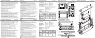
<strong>CLS</strong> <strong>24</strong>/<strong>SV</strong> Montage- und Betriebsanleitung<br />
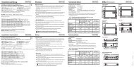
4. Produktbeschreibung<br />
Die dezentrale INOTEC Notlichtanlage <strong>CLS</strong> <strong>24</strong> ist ein Versorgungsgerät<br />
in Schutzklasse I für den Betrieb und die<br />
Überwachung von bis zu 80 Sicherheits- und Rettungszeichenleuchten.<br />
Je Abgang können bis zu 20 Leuchten<br />
in unterschiedlichen Schaltungsarten betrieben werden.<br />
Das <strong>CLS</strong> System beinhaltet:<br />
• Batterie für 1 Std., 3 Std. oder 8 Std. Notlichtbetrieb<br />
• 4 Stromkreisabgänge, geeignet für bis zu 20 Leuchten<br />
mit einer maximalen Anschlussleistung von max. 3A je<br />
Stromkreis (<strong>CLS</strong> <strong>24</strong>/<strong>SV</strong> und <strong>CLS</strong> <strong>Power</strong>)<br />
• 2 Stromkreisabgänge, geeignet für bis zu 20 Leuchten<br />
(<strong>CLS</strong> <strong>24</strong> - <strong>7Ah</strong>)<br />
• Steuerteil mit vierzeiligem Display für<br />
Statusinformationen<br />
• 4-kanaliger Lichtschalterabfrage<br />
• Integriertes Prüfbuch<br />
• Optionales Netzwerkmodul INOWEB<br />
Die Leuchten werden über eine zweiadrige Versorgungsleitung<br />
mit <strong>24</strong>V-Schutzkleinspannung versorgt<br />
und können über das Gerätesteuerteil programmiert<br />
werden. Dabei wird der eindeutigen Leuchtenadresse<br />
eine logische Verknüpfung mit einer Stromkreisadresse<br />
zugewiesen.<br />
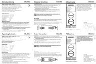
Das frei programmierbare Steuerteil hat vier Status-LED<br />
und ein vierzeiliges alphanummerisches Display zur<br />
Anzeige des jeweiligen Geräte- und Leuchtenzustandes.<br />
Über die serienmäßig integrierte PS/2-Schnittstelle<br />
können Textinformation zu den einzelnen Leuchten mit<br />
einer handelsüblichen Tastatur erfasst werden.<br />
Jederzeit können manuelle Tests zur Überprüfung ausgelöst<br />
werden. Ebenso sind automatische Tests zu frei programmierbaren<br />
Zeitpunkten möglich. Die Testergebnisse<br />
werden im integrierten Prüfbuch detailliert gespeichert<br />
und sind jederzeit abrufbar (ca. 1.000 Einträge).<br />
Vier potentialfreie Kontakte zur externen Fehlermeldung/Statusanzeige<br />
sind vorhanden. Einer dieser Kontakte<br />
ist frei programmierbar.<br />
Über ein optionales Netzwerkmodul kann der Zustand<br />
überall im Netzwerk per Webbrowser abgerufen werden.<br />
Der Zugriff auf die HTML-Seiten ist über ein frei wählbares<br />
Passwort zu schützen.<br />
<strong>CLS</strong> <strong>24</strong>/<strong>SV</strong> Mounting and Operating Instructions<br />
4. Product description<br />
The <strong>CLS</strong> <strong>24</strong> local INOTEC emergency lighting system is<br />
a protection class I supply device for using and monitoring<br />
up to 80 safety and emergency exit luminaires. You<br />
can operate up to 20 luminaires with different switching<br />
modes for each outgoing circuit.<br />
The <strong>CLS</strong> system includes:<br />
• Battery for 1 h, 3 h or 8 hours of emergency lighting<br />
• 4 outgoing circuits designed for up to 20 luminaires<br />
with a maximum connected output of max. 3A per<br />
circuit(<strong>CLS</strong> <strong>24</strong>/<strong>SV</strong> und <strong>CLS</strong> <strong>Power</strong>)<br />
• 2 outgoing circuits designed for up to20 luminaires (<strong>CLS</strong><br />
<strong>24</strong> - <strong>7Ah</strong>)<br />
• Controller with 4-row display for status information<br />
• 4-channel light sequence switching<br />
• Integrated logbook<br />
• Optional network module INOWEB<br />
The luminaires are supplied via a dual conductor supply<br />
lead with <strong>24</strong>V low voltage protection and can be<br />
programmed using the device controller. Programming<br />
involves assigning the luminaires unique address with<br />
a logical link to a circuit address.<br />
The programmable controller has 4 status LEDs and<br />
a 4-row alphanumeric display to indicate the current<br />
device and luminaire status. With the PS/2 interface builtin<br />
as standard, you can use a regular keyboard to enter<br />
textual information concerning each luminaire.<br />
You can conduct manual tests to check the system at any<br />
time, or have the system conduct automatic tests at any<br />
programmed time. Details of the test results are saved in<br />
the integrated logbook for you to view when you prefer<br />
(approx. 1000 entries).<br />
There are 4 voltfree contacts on the external error message/status<br />
display. One of these contacts can be programmed<br />
at will.<br />
An optional network module can be used to call up the<br />
status anywhere on the network via a web browser. Set any<br />
password you like to protect access to the HTML pages.<br />
7