Emergency Lighting Device CLS 24 - 7Ah CLS 24/SV CLS Power ...
Emergency Lighting Device CLS 24 - 7Ah CLS 24/SV CLS Power ...
Emergency Lighting Device CLS 24 - 7Ah CLS 24/SV CLS Power ...

Erfolgreiche ePaper selbst erstellen
Machen Sie aus Ihren PDF Publikationen ein blätterbares Flipbook mit unserer einzigartigen Google optimierten e-Paper Software.
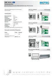
<strong>CLS</strong> <strong>24</strong>/<strong>SV</strong> Montage- und Betriebsanleitung<br />
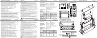
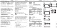
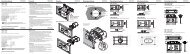
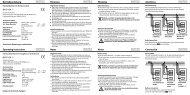
6.3. Elektrischer Anschluss<br />
Die Verkabelung erfolgt bei der <strong>CLS</strong> und <strong>CLS</strong> <strong>Power</strong> über<br />
die oberen Kabeleinführungen.<br />
Im Aufputzgehäuse der <strong>CLS</strong> ist auch eine rückseitige<br />
Kabeleinführung möglich. Dazu ist das vorgestanzte<br />
Blech in der Gehäuserückwand<br />
herauszubrechen.<br />
<strong>CLS</strong> <strong>24</strong>/<strong>SV</strong> Mounting and Operating Instructions<br />
6.3. Electrical connection<br />
The cabelling for the <strong>CLS</strong> and <strong>CLS</strong> <strong>Power</strong> is via the upper<br />
cable inlets.<br />
A rear side cable inlet is possible for the surfacemounted<br />
housing. Therefore the pre-stamped<br />
steel metal at the rear has to be breaked out.<br />
Netzanschluss<br />
Mains connection<br />
Lichtschalterabfrage<br />
Light sequence switching<br />
Lichtschalterabfrage<br />
Light sequence switching<br />
Lichtschalterabfrage<br />
Light sequence switching<br />
Lichtschalterabfrage<br />
Light sequence switching<br />
<strong>CLS</strong> MTB<br />
Externe Komponenten<br />
External components<br />
<strong>CLS</strong> Dimmer<br />
Ohne Funktion<br />
Not in use<br />
DPÜ<br />
Three-phase-monitor<br />
Meldetableau<br />
Mimic panel<br />
Leuchte 1 ... 20<br />
Luminaries 1…20<br />
Leuchte 1 ... 20<br />
Luminaries 1…20<br />
Leuchte 1 ... 20<br />
Luminaries 1…20<br />
Leuchte 1 ... 20<br />
Luminaries 1…20<br />
Netz<br />
PE L N<br />
LSA1<br />
N L<br />
LSA2<br />
N L<br />
LSA3<br />
N L<br />
LSA4<br />
N L<br />
R T G IBa IBp IBp SL FS +<strong>24</strong>V Opt.<br />
+<strong>24</strong>V<br />
– + – + – + Stoer<br />
T<br />
Betr.<br />
Bat.-B.<br />
SK1<br />
- +<br />
- +<br />
SK2<br />
- +<br />
- +<br />
SK3<br />
- +<br />
- +<br />
SK4<br />
- +<br />
- +<br />
InoWeb<br />
INOTEC<br />
Ein/On<br />
Ein/On<br />
Ein/On<br />
Ein/On<br />
Betrieb<br />
Operation<br />
Batt.-Betrieb<br />
Bat.-Operation<br />
Störung<br />
Failure<br />
OK<br />
Störung<br />
Failure<br />
Störung<br />
Failure<br />
Störung<br />
Failure<br />
Störung<br />
Failure<br />
SK 1 SK 2 SK 3 SK 4<br />
Lade Störung<br />
Charge failure<br />
1 2 3 4 5 6 7 8 9 10 11 12 13 14 15 16 17 18 19 20<br />
ESC<br />
14<br />
6.3.1. Netzanschluss<br />
Anschluss der Spannungsversorgung 230V AC an die<br />
Klemmen L, N, PE.<br />
6.3.2. Endstromkreise<br />
Das <strong>CLS</strong>-System besitzt 4 Endstromkreise (2 Endstromkreise<br />
bei <strong>CLS</strong>-<strong>7Ah</strong>) zur Überwachung von je 20 Leuchtenadressen.<br />
Die Endstromkreise können jeweils mit bis<br />
zu max. 3A belastet werden und sind mit 5A abgesichert.<br />
Dabei ist aber auf die Gesamtbelastung des ganzen Systems<br />
zu achten. 5. Technische Daten - Seite 10<br />
Der Einsatz von Kleinspannung (SELV) zur Versorgung<br />
der Notbeleuchtung vereinfacht die Verkabelung und<br />
eine PE-Ader entfällt. Bitte beachten Sie dazu die Angaben<br />
zur Leitungslänge im Anhang C. Leitungslängen<br />
- Seite 55<br />
Über die Klemmen + und -, die pro Endstromkreis<br />
doppelt ausgeführt sind, werden die Leuchten angeschlossen.<br />
Jede Leuchte besitzt eine eindeutige ID, die<br />
dann bei der Programmierung einer lokalen Adresse im<br />
Stromkreis zugeordnet werden muss. 8.3.3. Leuchten<br />
programmieren - Seite 29<br />
Bei der De-/Montage der Leuchten ist darauf<br />
zu achten, dass die IDs auf Gehäuse und Modul<br />
übereinstimmen!<br />
Im Fall der Nachinstallation ist darauf zu achten, dass<br />
jede Leuchten-ID pro Stromkreis nur einmal an der <strong>CLS</strong><br />
angeschlossen wird!<br />
Max. Leitungslänge Endstromkreis Anhang C. Leitungslängen<br />
- Seite 55<br />
6.3.1. Mains connection<br />
Connect the 230V AC voltage supply to terminals L,<br />
N and PE.<br />
6.3.2. Final circuits<br />
The <strong>CLS</strong> system has 4 final circuits (2 final circuits at <strong>CLS</strong>-<br />
<strong>7Ah</strong>) to each monitor 20 luminaire addresses. The final<br />
circuits can each carry a load of max. 3A with a 5A fuse.<br />
Please make sure the total load on the entire system is<br />
not exceeded. 5. Technical data - page 10<br />
Using low voltage (SELV) to supply the emergency lighting<br />
simplifies cabling and eliminates the need for a PE<br />
conductor. Please observe the wire lengths specified in<br />
Appendix C. Wire lengths - Seite 55<br />
The luminaires are connected at terminals + and -, of<br />
which there are 2 per final circuit. Each luminaire has a<br />
unique ID which you must then assign to a local address<br />
on the circuit when you program it. 8.3.3. Programming<br />
luminaires - page 29<br />
When (un)installing the luminaires, make sure<br />
the IDs on the casing and the module match.<br />
In the event of replacement installation, make sure an<br />
identical luminaire ID is not connected more than once<br />
to a circuit of a <strong>CLS</strong>.<br />
Max. wire length of final circuits Appendix C. Wire<br />
lengths - Seite 55