14:53 - AEG Haustechnik
14:53 - AEG Haustechnik
14:53 - AEG Haustechnik

Sie wollen auch ein ePaper? Erhöhen Sie die Reichweite Ihrer Titel.
YUMPU macht aus Druck-PDFs automatisch weboptimierte ePaper, die Google liebt.
Replacing an existing ELFAMATIC µC 2100<br />
The device must be connected as shown in the circuit diagram.<br />
Removal<br />
To remove the controller, release the top part from the base (as<br />
described above) and disconnect the connecting cables.<br />
Then release the base from the rail as shown in the illustration<br />
below.<br />
For the Fitter<br />
Sensor<br />
Normally, the installation location of the atmospheric sensor should be selected according to the<br />
following criteria:<br />
● Installation according to the illustration below<br />
● Min. height above ground: 2.5 m<br />
● The sensor should be mounted on the side of the building on which the main rooms to be heated<br />
are located (avoid mounting on the north side of the building where possible)<br />
● The sensor must be mounted at a sufficient distance from doors, windows, exhaust-air ducts, etc.<br />
The cable between the sensor and control unit must be suitable for mains voltage.<br />
2.3.2 Electrical connection<br />
The terminal assignment is given in the table below.<br />
Sensor<br />
installation<br />
Preliminary check<br />
● Insulation test on all cables (without consumers)<br />
● Resistance test (turn the rotary knob of charging controller on each heater clockwise as far as it<br />
will go)<br />
1. At Z1 and Z2 of the ELFAMATIC µC 3000:<br />
R= 176 Ω ... 100 kΩ<br />
The measured resistance must not be less than 176 Ω.<br />
2. At W1 and W2 of the ELFAMATIC µC 3000:<br />
Atmospheric sensor<br />
R = See table in page 24<br />
Make sure that the correct sensor code is entered.<br />
● Switch on the mains voltage and measure between L and N.<br />
● Simulate the LF release and measure the voltage between LF and N.<br />
● Switch off the mains voltage.<br />
Attach the top part of the housing to the base.<br />
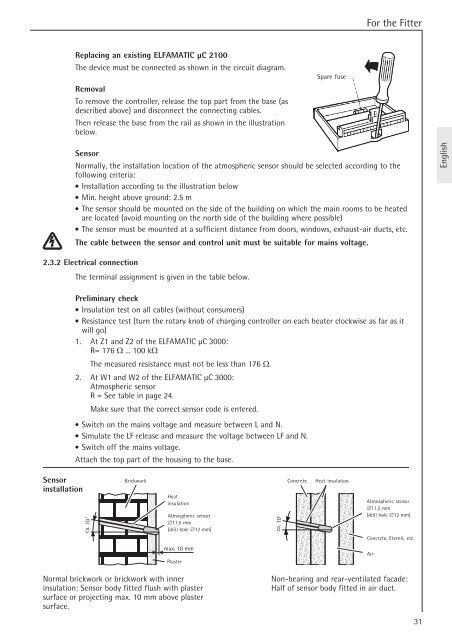
ca. 10˚<br />
Brickwork<br />
Heat<br />
insulation<br />
Atmospheric sensor<br />
∅11,5 mm<br />
(drill hole ∅12 mm)<br />
max. 10 mm<br />
Plaster<br />
Normal brickwork or brickwork with inner<br />
insulation: Sensor body fitted flush with plaster<br />
surface or projecting max. 10 mm above plaster<br />
surface.<br />
ca. 10˚<br />
Spare fuse<br />
Concrete Heat insulation<br />
Atmospheric sensor<br />
∅11,5 mm<br />
(drill hole ∅12 mm)<br />
Concrete, Eternit, etc.<br />
Non-bearing and rear-ventilated facade:<br />
Half of sensor body fitted in air duct.<br />
Air<br />
31<br />
English