Ditec Smart Plus - DITEC ENTREMATIC
Ditec Smart Plus - DITEC ENTREMATIC
Ditec Smart Plus - DITEC ENTREMATIC

Erfolgreiche ePaper selbst erstellen
Machen Sie aus Ihren PDF Publikationen ein blätterbares Flipbook mit unserer einzigartigen Google optimierten e-Paper Software.
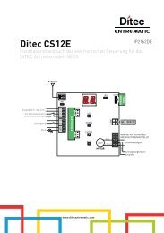
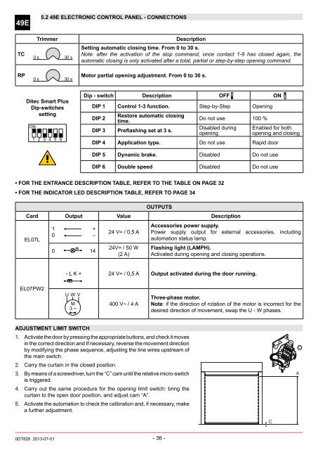
49E5.2 49E ELECTRONIC CONTROL PANEL - ConnectionsTCTrimmer0 s 30 sDescriptionSetting automatic closing time. From 0 to 30 s.Note: after the activation of the stop command, once contact 1-9 has closed again, theautomatic closing is only activated after a total, partial or step-by-step opening command.RP Motor partial opening adjustment. From 0 to 30 s.0 s 30 s<strong>Ditec</strong> <strong>Smart</strong> <strong>Plus</strong>Dip-switchessettingON1 2 3 4 5 6Dip - switch Description OFF ONDIP 1 Control 1-3 function. Step-by-Step OpeningDIP 2Restore automatic closingtime.DIP 3 Preflashing set at 3 s.Do not use 100 %Disabled duringopeningEnabled for bothopening and closingDIP 4 Application type. Do not use Rapid doorDIP 5 Dynamic brake. Disabled Do not useDIP 6 Double speed Disabled Do not use• FOR THE ENTRANCE DESCRIPTION TABLE, REFER TO THE TABLE ON PAGE 32• FOR THE INDICATOR LED DESCRIPTION TABLE, REFER TO PAGE 34OUTPUTSCard Output Value DescriptionEL07L1 +0 –0 1424 V= / 0,5 A24V= / 50 W(2 A)Accessories power supply.Power supply output for external accessories, includingautomation status lamp.Flashing light (LAMPH).Activated during opening and closing operations.- L K + 24 V= / 0,5 A Output activated during the door running.EL07PW2U W VM3 ~400 V~ / 4 AThree-phase motor.Note: if the direction of rotation of the motor is incorrect for thedesired direction of movement, swap the U - W phases.ADJUSTment limit switch1. Activate the door by pressing the appropriate buttons, and check it movesin the correct direction and If necessary, reverse the movement directionby modifying the phase sequence, adjusting the line wires upstream ofthe main switch.2. Carry the curtain in the closed position.3. By means of a screwdriver, turn the “C” cam until the relative micro-switchis triggered.4. Carry out the same procedure for the opening limit switch: bring thecurtain to the open door position, and adjust cam “A”.5. Activate the automation to check the calibration and, if necessary, makea further adjustment.AACC0DT826 2013-07-01- 36 -