
Erfolgreiche ePaper selbst erstellen
Machen Sie aus Ihren PDF Publikationen ein blätterbares Flipbook mit unserer einzigartigen Google optimierten e-Paper Software.
Version ; 200228<br />
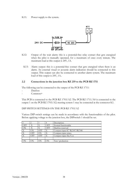
K11: Power supply to the system.<br />
K12: Output of the wait alarm: this is a potential-free relay contact that gets energised<br />
when the pilot is manually operated, for a maximum of once every minute. The<br />
maximum load at this output is 24V, 1A.<br />
K13: Alarm output: this is a potential-free contact that gets energised when there is an<br />
alarm. An external visual or acoustic alarm indication should be connected to this<br />
output. This output can also be connected to another alarm system. The maximum<br />
load of this output is 24V, 1A..<br />
2.2 Connections in the junction box RZ 219 to the PCB RZ 1711<br />
The following can be connected to the output of the PCB RZ 1711:<br />
- Danfoss<br />
- Common+<br />
This PCB is connected to the PCB RZ 1703/A2. The PCB RZ 1711/A0 is connected to the<br />
output 1 on the PCB RZ 1703/A2; steering system 1 may be connected at the connector K1.<br />
DIP SWITCH SETTINGS ON THE PCB RZ 1703/A2<br />
Various DIP-switch settings can be made in accordance with the functionalities of the pilot.<br />
Before applying voltage to the junction box, the DIPswitch 1 should be set.<br />
1 2 3 4 Description:<br />
OFF X X OFF Normal functionality<br />
ON X X OFF Danfoss reserved<br />
X ON OFF X Compass input K7 RZ347/RZ348<br />
X OFF ON X Compass input nmea<br />
X OFF OFF X Compass input Sin/Cos<br />
ON ON ON ON Test/ production<br />
38