Polymer Films as Acoustic Matching Layers - Khuri-Yakub ...
Polymer Films as Acoustic Matching Layers - Khuri-Yakub ...
Polymer Films as Acoustic Matching Layers - Khuri-Yakub ...

You also want an ePaper? Increase the reach of your titles
YUMPU automatically turns print PDFs into web optimized ePapers that Google loves.
ABSTRACT<br />
We have investigated usin some polymer films<br />
such <strong>as</strong> polyimide and Parylene ?or acoustic impedance<br />
matching applications. Polyimide films were spin<br />
coated and Parylene films were vapor deposited on<br />
silicon and l<strong>as</strong>s substrates, respectively. The<br />
impedance, ve P ocity of sound and acoustic attenuation<br />
of these films were me<strong>as</strong>ured in the 70-230 MHz<br />
frequency range. The curing temperature of the<br />
polyimide films w<strong>as</strong> also varied to determine the<br />
dependence of the material properties on processing<br />
conditions. The impedance of these films were<br />
me<strong>as</strong>ured to be in the 2.7 to 3.7 Mrayl range.<br />
Therefore, these films can be used to obtain a good<br />
acoustic matching between most liquids and most low<br />
impedance solids. The me<strong>as</strong>ured Q values also<br />
promise operation at frequencies up to a few hundred<br />
MHz.<br />
INTRODUCTION<br />
Efficient coupling of acoustic fields from a liquid<br />
into a solid require a quarter-wave matching layer due<br />
to the large impedance mismatch between most<br />
liquids and solids. For most applications the<br />
impedance of the matching layer h<strong>as</strong> to be in the 3 to<br />
10 Mrayl range. Unfortunately, there are not a lot of<br />
materials available with an impedance in this<br />
frequency range. Typically at gi ahertz frequencies a<br />
vacuum-deposited thin-film 07 borosilicate gl<strong>as</strong>s<br />
(impedance, Z, is 11 Mrayls) or amorphous carbon<br />
(Z=8 Mrayls) is used <strong>as</strong> matching layers.1 At low<br />
megahertz frequencies thin sheets of solids such <strong>as</strong><br />
epoxy composites are laminated on the substrate <strong>as</strong><br />
anti-reflection coatings. When frequencies on the<br />
order of a few hundred megahertz are used, however,<br />
neither of these techniques can be applied. Typical<br />
wavelengths in solids are on the order of a few tens of<br />
microns at frequencies around 100 MHz. Vacuum<br />
deposition of materials at these thicknesses is either<br />
ver costly or impossible at all. Laminating materials<br />
wit{ such thicknesses can not be done because<br />
polishing materials down to such thicknesses is very<br />
difficult.<br />
We have investigated polymer films such <strong>as</strong><br />
polyimide and Parylene <strong>as</strong> acoustic matching layers at<br />
frequencies in the 100 to 200 MHz range. The<br />
*E. L. Ginzton Laboratory, Stanford University,<br />
Stanford, CA. 94305<br />
1051-0117/90/0000-1337 $1.00 0 1990 IEEE<br />
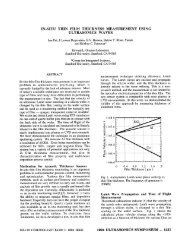
POLYMER FILMS AS ACOUSTIC MATCHING LAYERS<br />
B. Hadimioglu and B. T. <strong>Khuri</strong>-<strong>Yakub</strong>*<br />
XEROX Palo Alto Research Center<br />
3333 Coyote Hill Road<br />
Palo Alto, CA. 94304<br />
me<strong>as</strong>urements indicate that these films promise good<br />
transmission efficiencies between most liquids and<br />
especially low impedance solids such <strong>as</strong> silicon, gl<strong>as</strong>s<br />
and quartz.<br />
EXPERIMENTAL PROCEDURE<br />
The acoustic me<strong>as</strong>urements were performed using<br />
a pulse-echo detection system. Figure 1 shows a<br />
diagram of the setup. Typically 200 nsec-wide pulses<br />
of rf signal are applied into a LiNbO3 acoustic<br />
transducer. The transducer is bonded on a double side<br />
polished quartz crystal and it generates plane sound<br />
waves in the quartz rod. The transducer h<strong>as</strong> a center<br />
frequency of 130 MHz although its broad bandwidth<br />
allows me<strong>as</strong>urements in the 70 to 230 MHz frequency<br />
range. The amplitude of the signal applied into the<br />
transducer is controlled by a precision step attenuator.<br />
The signals received from the transducer are detected<br />
using a low-noise superheterodyne receiver. The<br />
attenuation value of the step attenuator is recorded <strong>as</strong><br />
the frequency is varied to determine the frequency<br />
response of the device-under-test. The system h<strong>as</strong> a<br />
dynamic range of over 80 dBs with a me<strong>as</strong>urement<br />
accuracy of better than T.5 dB over the entire<br />
frequency range.<br />
Figure 2 shows a diagram of the transducer-<br />
me<strong>as</strong>ured device configuration along with various<br />
signals received from the transducer. In order to<br />
RFmclllator FETSwltch Digital<br />
Attenuator<br />
Mixer<br />
I’ I<br />
‘a +h<br />
Control<br />
Power Splitter Transducer<br />
Test<br />
wafer<br />
Figure 1. The rf-electronics of the me<strong>as</strong>urement system<br />
1990 ULTRASONICS SYMPOSIUM - 1337
Liquid<br />
(Zl)<br />
<strong>Matching</strong><br />
Laver<br />
Ar (Reflection loss)= A,(mat) - A,(ref)<br />
At (Transmission loss) = At(ref) - At(mat)<br />
Figure 2. Me<strong>as</strong>urement setup with the various rfpulses<br />
received.<br />
accurately determine the losses in the matching layer,<br />
first the amplitude of the reflected and transmitted<br />
signals Al(ref) and At(ref) were recorded without the<br />
matching layer present in the system <strong>as</strong> shown in<br />
Figure 2. Then the same echoes were me<strong>as</strong>ured with<br />
the matching layer present on the wafer. The<br />
difference between these signals represent the<br />
amplitude of the reflection and transmission<br />
coefficients of the liquid/matching layer/solid<br />
configuration, respectively.<br />
In order to estimate the mechanical properties of<br />
the material under test, the me<strong>as</strong>ured reflected and<br />
transmission coefficients were compared to the values<br />
predicted by a theoretical calculation of the response<br />
of the system. The theoretical reflection and<br />
transmission coefficients of the matching layer are<br />
given by<br />
and<br />
1338 - 1990 ULTRASONICS SYMPOSIUM<br />
where<br />
Aloss is given by<br />
where<br />
and Zj, is the input impedance of the matching<br />
layer/solid combination looking from the liquid side<br />
given by<br />
The attenuation constant a of the matching layer is<br />
<strong>as</strong>sumed to incre<strong>as</strong>e <strong>as</strong> the frequency to the power y.<br />
Z/, Z and Z, are the impedance of the liquid, matching<br />
layer and substrate, respectively. The matching layer<br />
h<strong>as</strong> a thickness of t and sound velocity of v. An<br />
alternative definition for the attenuation constant is<br />
the Q of the layer where Q=nf/va and f is the<br />
frequency.<br />
It should be noted here that since the ph<strong>as</strong>e of the<br />
reflection coefficient is not me<strong>as</strong>ured, there are two<br />
impedances that will match the me<strong>as</strong>ured magnitude<br />
of the reflection and transmission coefficients. These<br />
impedances are located symmetrically around the<br />
quarter-wave matching impedance Zv4= (Z/ZJW In<br />
order to determine the impedance of the matching<br />
layer unambiguously, me<strong>as</strong>urements were done using<br />
both water and isopropyl alcohol <strong>as</strong> the coupling<br />
liquid. Since isopropyl h<strong>as</strong> an impedance much less<br />
than that of water, it is e<strong>as</strong>y to determine the<br />
impedance of the matching layer accurately.<br />
The pol imide films2 were applied by spin coating<br />
on one sde of 2.5 mm thick double side polished<br />
silicon wafers. The wafers were spun at 1200<br />
rpm for 60 seconds which yielded final film thicknesses<br />
of about 5 pm. After a drying at 90°C for 10 minutes, a<br />
(3-stage cure w<strong>as</strong> done at 140OC for 30 minutes. Holes<br />
were photolithographically etched in the polyimide to<br />
expose the silicon surface. These holes allow the<br />
me<strong>as</strong>urement of the polyimide thickness <strong>as</strong> well <strong>as</strong> the<br />
me<strong>as</strong>urement of the reference data. A final high<br />
temperature cure w<strong>as</strong> then applied for 1 hour. In<br />
order to determine the dependence of the mechanical<br />
properties of the olyimide films on processing<br />
conditions, the fina P cure temperature w<strong>as</strong> varied<br />
between 14OOC and 325OC.<br />
The Parylene films were applied using vapor ph<strong>as</strong>e
deposition on pyrex gl<strong>as</strong>s plates. Two different types<br />
of Parylene films were me<strong>as</strong>ured, Parylene-N and<br />
Parylene-C. The thickness of all the films were<br />
mea ured by an a-Step machine with an accuracy of<br />
T 508.<br />
RESULTS<br />
Figures 3 and 4 show a typical set of data along<br />
with theoretical curves fitted on the experimental<br />
data. Figures 3(a) and (b) show the reflection and<br />
transmission loss, respectively, with water <strong>as</strong> the<br />
coupling fluid. Figures 4(a) and (b) are corresponding<br />
plots for isopropyl alcohol: The fit between the<br />
experimental and theoretical curves are excellent in<br />
most c<strong>as</strong>es. The uncertainty in determining the<br />
impedance of the matchin layer w<strong>as</strong> found to be<br />
T.05 Mrayl. The accuracy o 3 the velocity estimation is<br />
better than 50 m/sec. The-attenuation value of the<br />
J<br />
z<br />
: 51,,<br />
1<br />
,I<br />
, J - / = + , .<br />
..* . .<br />
'5 0 I00 150 200 250<br />
FREQUENCY (MHz ><br />
PMI-325 HRTER<br />
Figure3. (a) Me<strong>as</strong>ured reflection loss and (b)<br />
transmission loss for a polyimide film.<br />
Coupling liquid is water. Solid line is the<br />
theoretical curve fitted on the data.<br />
..<br />
PM1-325 15C<br />
20 ,<br />
E<br />
!<br />
I<br />
'5 t I I 1<br />
0,I. ~ ' 100 ~ " ~ 150 ~ ~ 200 ."""' " ~ c20 ~ ~ '<br />
FREQUENCY (MHzI<br />
Figure4. (a) Me<strong>as</strong>ured reflection loss and (b)<br />
transmission loss for a olyimide film.<br />
Couplin liquid is isopropy P alcohol. Solid<br />
line is $e theoretical curve fitted on the<br />
data.<br />
films, with the exception of Parylene-C, were found to<br />
be such that typical Q w<strong>as</strong> greater than 100 at 100<br />
MHz. The power dependence, y, of the attenuation<br />
constant w<strong>as</strong> <strong>as</strong>sumed to be 2 in all calculations. Such<br />
attenuation values are too low to perturb the<br />
me<strong>as</strong>ured reflection and. transmission losses<br />
significantly in the me<strong>as</strong>urement frequenc<br />
The accuracy of the Q me<strong>as</strong>urement is, there/or'ea.%<br />
and should be considered <strong>as</strong> a lower limit for the<br />
actual Q values. In order to determine the acoustic<br />
attenuation more accurately, higher frequency<br />
me<strong>as</strong>urements are needed.<br />
Table 1 shows the results of the me<strong>as</strong>urements. It<br />
can be seen that the impedance and sound velocity of<br />
the polyimide films are near 3.6 Mra I and 2.4 kmlsec,<br />
respectively. The change in the mec t! anical properties<br />
of the polyimide films with the cure temperature is<br />
1990 ULTRASONICS SYMPOSIUM - 1339
Cure<br />
Sample # Material Temperature 2 Q<br />
(kmysec, (Mrayls) (at 100 MHrl<br />
CO<br />
PM1-325 Polyimide 325 2.43 36 KN)<br />
PM1-240 Polyimide 240 2 55 36 1w<br />
PM1-180 Polyimide 180 2 53 37 100<br />
PM1-140 Polyimide 140 2 57 3 75 100<br />
PARNl ParyleneN<br />
- 2.1 2.85 100<br />
Table 1. The results of the me<strong>as</strong>urements.<br />
very small with a slight incre<strong>as</strong>e of the impedance <strong>as</strong><br />
the cure temperature is decre<strong>as</strong>ed. The Parylene films<br />
show a sound velocity of 2.2 km/sec with a lower<br />
impedance of about 2.9 Mrayl.<br />
Table 2 shows the predicted operation of<br />
polyimide films cured at 325OC for matching sound<br />
from water into various low impedance solids at<br />
frequencies <strong>as</strong> high <strong>as</strong> 600 MHz. The Q is <strong>as</strong>sumed to<br />
be 200 at 100 MHz with an inverse frequency<br />
dependence. It can be seen that these films offer a<br />
significant improvement in the transmission and<br />
reflection losses at these frequencies for the substrates<br />
considered. The acoustic attenuation is relatively low<br />
compared to the data reported by Selfridge3 for low<br />
impedance materials such <strong>as</strong> pl<strong>as</strong>tics. Both polyimide<br />
and Parylene also offer e<strong>as</strong>y application with thickness<br />
ranging from sub-micron to several microns. These<br />
materials are also relatively inert and stable4 which<br />
should make them ideal for matching layer<br />
applications.<br />
COUPLING SOUND FROM WATER INTO SILICON AND GLASS<br />
<strong>Matching</strong> layer: Polyimide (325%). U4 thick<br />
Table 2. Predicted response of polyimide films cured<br />
at 325oC.<br />
CONCLUSION<br />
We have me<strong>as</strong>ured the acoustic impedance,<br />
velocity of sound and mechanical Q of polymide and<br />
Parylene films. The me<strong>as</strong>ured impedances show that<br />
both of these materials should yield a significant<br />
improvement in the efficiency of coupling of sound<br />
1340 - 1990 ULTRASONICS SYMPOSIUM<br />
from liquids to low impedance solids such <strong>as</strong> silicon,<br />
l<strong>as</strong>s and quartz. The acoustic attenuation for these<br />
4. ilms are also low enough to suggest operation of<br />
these films up to a few hundred megahertz.<br />
ACKNOWLEDGEMENTS<br />
The authors wish to thank Robert Allen and<br />
Barbara Minott for supplying the polyimide wafers.<br />
1.<br />
2.<br />
3.<br />
4.<br />
REFERENCES<br />
D. Rugar, "Cryogenic <strong>Acoustic</strong> Microscopy," Ph.D.<br />
Dissertation, Stanford University (1981).<br />
PIX-1400, Hitachi Chemical Co. Ltd., Japan.<br />
A. R. Selfridge, "Approximate Material Properties<br />
of Isotropic Materials," IEEE Trans. Sonics and<br />
Ultr<strong>as</strong>on., SU-32, 381 (1985).<br />
See, for example, <strong>Polymer</strong>s for Electronic<br />
Applications, edited by J. H. Lai (CRC, Florida,<br />
1989), Chapters 2 and 3.