chapter 12 hydraulic transient design for pipeline systems
chapter 12 hydraulic transient design for pipeline systems
chapter 12 hydraulic transient design for pipeline systems
Create successful ePaper yourself
Turn your PDF publications into a flip-book with our unique Google optimized e-Paper software.
<strong>12</strong>.10 Chapter Twelve<br />
HYDRAULIC TRANSIENT DESIGN FOR PIPELINE SYSTEMS<br />
• Flow rate. Capacity Q at operating point in chosen units.<br />
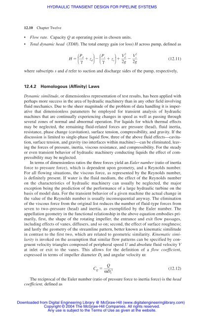
• Total dynamic head (TDH). The total energy gain (or loss) H across pump, defined as<br />
H � ⎛ ⎜� ⎝ Pd<br />
� � zd γ<br />
⎞<br />
⎟<br />
⎠ � ⎛ ⎜� ⎝ Ps<br />
γ<br />
� � z s<br />
⎞<br />
⎟<br />
⎠<br />
2 2<br />
d Vs<br />
� �V � � �� (<strong>12</strong>.11)<br />
2g 2g<br />
where subscripts s and d refer to suction and discharge sides of the pump, respectively,<br />
<strong>12</strong>.4.2 Homologous (Affinity) Laws<br />
Dynamic similitude, or dimensionless representation of test results, has been applied with<br />
perhaps more success in the area of <strong>hydraulic</strong> machinery than in any other field involving<br />
fluid mechanics. Due to the sheer magnitude of the problem of data handling it is imperative<br />
that dimensionless parameters be employed <strong>for</strong> <strong>transient</strong> analysis of <strong>hydraulic</strong><br />
machines that are continually experiencing changes in speed as well as passing through<br />
several zones of normal and abnormal operation. For liquids <strong>for</strong> which thermal effects<br />
may be neglected, the remaining fluid-related <strong>for</strong>ces are pressure (head), fluid inertia,<br />
resistance, phase change (cavitation), surface tension, compressibility, and gravity. If the<br />
discussion is limited to single-phase liquid flow, three of the above fluid effects—cavitation,<br />
surface tension, and gravity (no interfaces within machine)—can be eliminated, leaving<br />
the <strong>for</strong>ces of pressure, inertia, viscous resistance, and compressibility. For the steady<br />
or even <strong>transient</strong> behavior of <strong>hydraulic</strong> machinery conducting liquids the effect of compressibility<br />
may be neglected.<br />
In terms of dimensionless ratios the three <strong>for</strong>ces yield an Euler number (ratio of inertia<br />
<strong>for</strong>ce to pressure <strong>for</strong>ce), which is dependent upon geometry, and a Reynolds number.<br />
For all flowing situations, the viscous <strong>for</strong>ce, as represented by the Reynolds number,<br />
is definitely present. If water is the fluid medium, the effect of the Reynolds number<br />
on the characteristics of <strong>hydraulic</strong> machinery can usually be neglected, the major<br />
exception being the prediction of the per<strong>for</strong>mance of a large <strong>hydraulic</strong> turbine on the<br />
basis of model data. For the <strong>transient</strong> behavior of a given machine the actual change in<br />
the value of the Reynolds number is usually inconsequential anyway. The elimination<br />
of the viscous <strong>for</strong>ce from the original list reduces the number of fluid-type <strong>for</strong>ces from<br />
seven to two–pressure (head) and inertia, as exemplified by the Euler number. The<br />
appellation geometry in the functional relationship in the above equation embodies primarily,<br />
first, the shape of the rotating impeller, the entrance and exit flow passages,<br />
including effects of vanes, diffusers, and so on; second, the effect of surface roughness;<br />
and lastly the geometry of the streamline pattern, better known as kinematic similitude<br />
in contrast to the first two, which are related to geometric similarity. Kinematic similarity<br />
is invoked on the assumption that similar flow patterns can be specified by congruent<br />
velocity triangles composed of peripheral speed U and absolute fluid velocity V<br />
at inlet or exit to the vanes. This allows <strong>for</strong> the definition of a flow coefficient,<br />
expressed in terms of impeller diameter D I and angular velocity ω:<br />
Q<br />
CQ � �� 3<br />
(<strong>12</strong>.<strong>12</strong>)<br />
ωDI<br />
The reciprocal of the Euler number (ratio of pressure <strong>for</strong>ce to inertia <strong>for</strong>ce) is the head<br />
coefficient, defined as<br />
Downloaded from Digital Engineering Library @ McGraw-Hill (www.digitalengineeringlibrary.com)<br />
Copyright © 2004 The McGraw-Hill Companies. All rights reserved.<br />
Any use is subject to the Terms of Use as given at the website.


