

chapter 12 hydraulic transient design for pipeline systems
chapter 12 hydraulic transient design for pipeline systems
chapter 12 hydraulic transient design for pipeline systems

You also want an ePaper? Increase the reach of your titles
YUMPU automatically turns print PDFs into web optimized ePapers that Google loves.
<strong>12</strong>.6 Chapter Twelve<br />
HYDRAULIC TRANSIENT DESIGN FOR PIPELINE SYSTEMS<br />
<strong>12</strong>.3.3 Definition of Hydraulic Per<strong>for</strong>mance of Valves<br />
The <strong>hydraulic</strong> per<strong>for</strong>mance of a valve depends upon the flow passage through the valve<br />
opening and the subsequent recovery of pressure. The <strong>hydraulic</strong> characteristics of a valve<br />
under partial to fully opened conditions typically relate the volumetric flow rate to a characteristic<br />
valve area and the head loss ∆H across the valve. The principal fluid properties<br />
that can affect the flow characteristics are fluid density ρ, fluid viscosity µ, and liquid<br />
vapor pressure p v if cavitation occurs. Except <strong>for</strong> small valves and/or viscous liquids or<br />
both, Reynolds number effects are usually not important, and will be neglected with reference<br />
to water. A valve in a <strong>pipeline</strong> acts as an obstruction, disturbs the flow, and in general<br />
causes a loss in energy as well as affecting the pressure distribution both upstream and<br />
downstream. The characteristics are expressed either in terms of (1) flow capacity as a<br />
function of a defined pressure drop or (2) energy dissipation (headloss) as a function of<br />
pipe velocity. In both instances the pressure or head drop is usually the difference in total<br />
head caused by the presence of the valve itself, minus any loss caused by regular pipe friction<br />
between measuring stations.<br />
The proper manner in determining ∆H experimentally is to measure the <strong>hydraulic</strong><br />
grade line (HGL) far enough both upstream and downstream of the valve so that uni<strong>for</strong>m<br />
flow sections to the left of and to the right of the valve can be established, allowing <strong>for</strong> the<br />
extrapolation of the energy grade lines (EGL) to the plane of the valve. Otherwise, the<br />
valve headloss is not properly defined. It is common to express the <strong>hydraulic</strong> characteristics<br />
either in terms of a headloss coefficient K L or as a discharge coefficient C f where A v<br />
is the area of the valve at any opening, and ∆H is the headloss defined <strong>for</strong> the valve.<br />
Frequently a discharge coefficient is defined in terms of the fully open valve area. The<br />
<strong>hydraulic</strong> coefficients embody not only the geometric features of the valve through A v but<br />
also the flow characteristics.<br />
Unless uni<strong>for</strong>m flow is established far upstream and downstream of a valve in a<br />
<strong>pipeline</strong> the value of any of the coefficients can be affected by effects of nonuni<strong>for</strong>m flow.<br />
It is not unusual <strong>for</strong> investigators to use only two pressure taps—one upstream and one<br />
downstream, frequently 1 and 10 diameters, respectively. The flow characteristics of<br />
valves in terms of pressure drop or headloss have been determined <strong>for</strong> numerous valves<br />
by many investigators and countless manufacturers. Only a few sets of data and typical<br />
curves will be presented here <strong>for</strong> ball, butterfly, and gate, ball, butterfly, and gate valves<br />
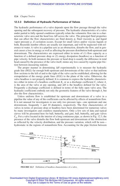
C D . For a valve located in the interior of a long continuous pipe, as shown in Fig. <strong>12</strong>.3, the<br />
presence of the valve disturbs the flow both upstream and downstream of the obstruction<br />
as reflected by the velocity distribution, and the pressure variation, which will be non—<br />
hydrostatic in the regions of nonuni<strong>for</strong>m flow. Accounting <strong>for</strong> the pipe friction between<br />
V2<br />
�� 2g<br />
FIGURE <strong>12</strong>.3 Definition of headloss characteristics of a valve.<br />
Downloaded from Digital Engineering Library @ McGraw-Hill (www.digitalengineeringlibrary.com)<br />
Copyright © 2004 The McGraw-Hill Companies. All rights reserved.<br />
Any use is subject to the Terms of Use as given at the website.


