

chapter 12 hydraulic transient design for pipeline systems
chapter 12 hydraulic transient design for pipeline systems
chapter 12 hydraulic transient design for pipeline systems

Create successful ePaper yourself
Turn your PDF publications into a flip-book with our unique Google optimized e-Paper software.
<strong>12</strong>.<strong>12</strong> Chapter Twelve<br />
HYDRAULIC TRANSIENT DESIGN FOR PIPELINE SYSTEMS<br />
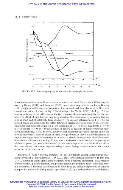
FIGURE <strong>12</strong>.5 Simulated pump trip without valves in a single-<strong>pipeline</strong> system.<br />
abnormal operation, as well as served to rein<strong>for</strong>ce the need <strong>for</strong> test data. Following the<br />
work by Knapp (1941) and Swanson (1953), and a summary of their results by Donsky<br />
(1961), eight possible zones of operation, four normal and four abnormal, will be discussed<br />
here with reference to Fig. <strong>12</strong>.6, developed by Martin (1983). In Fig. <strong>12</strong>.6 the<br />
head H is shown as the difference in the two reservoir elevations to simplify the illustration.<br />
The effect of pipe friction may be ignored <strong>for</strong> this discussion by assuming that the<br />
pipe is short and of relatively large diameter. The regions referred to on Fig. <strong>12</strong>.6 are<br />
termed zones and quadrants, the latter definition originating from plots of lines of constant<br />
head and constant torque on a flow-speed plane (v � α axes). Quadrants I (v � 0,<br />
α � 0) and III (v � 0, α � 0) are defined in general as regions of pump or turbine operation,<br />
respectively. It will be seen, however, that abnormal operation (neither pump nor<br />
turbine mode) may occur in either of these two quadrants. A very detailed description of<br />
each of the eight zones of operation is in order. It should be noted that all of the conditions<br />
shown schematically in Fig. <strong>12</strong>.6 can be contrived in a laboratory test loop using an<br />
additional pump (or two) as the master and the test pump as a slave. Most, if not all, of<br />
the zones shown can also be experienced by a pump during a <strong>transient</strong> under the appropriate<br />
set of circumstances.<br />
Quadrant I. Zone A (normal pumping) in Fig. <strong>12</strong>.6 depicts a pump under normal operation<br />
<strong>for</strong> which all four quantities— Q, N, H, and T are regarded as positive. In this case<br />
Q � 0, indicating useful application of energy. Zone B (energy dissipation) is a condition<br />
of positive flow, positive rotation, and positive torque, but negative head—quite an abnormal<br />
condition. A machine could operate in Zone B by (1) being overpowered by another<br />
pump or by a reservoir during steady operation, or (2) by a sudden drop in head during a<br />
Downloaded from Digital Engineering Library @ McGraw-Hill (www.digitalengineeringlibrary.com)<br />
Copyright © 2004 The McGraw-Hill Companies. All rights reserved.<br />
Any use is subject to the Terms of Use as given at the website.


