

chapter 12 hydraulic transient design for pipeline systems
chapter 12 hydraulic transient design for pipeline systems
chapter 12 hydraulic transient design for pipeline systems

You also want an ePaper? Increase the reach of your titles
YUMPU automatically turns print PDFs into web optimized ePapers that Google loves.
<strong>12</strong>.26 Chapter Twelve<br />
Some codes do not simulate water column separation, but instead only maintain the<br />
pressure at cavity location at vapor pressure. The results of such an analysis are invalid, if<br />
indeed an actual cavity occurred, at some time subsequent to cavity <strong>for</strong>mation. This technique<br />
is only useful to know if a cavity could have occurred, as there can be no assessment<br />
of the consequences of column separation. The inability of any code to model water<br />
column separation has the following implications: (1) the seriousness of any column separation<br />
event, if any, can not be determined, and (2) once vapor pressure is attained, the<br />
computation model loses its ability to predict adequately system <strong>transient</strong>s. If negative<br />
pressures below 138 kPa (20 psig) are not to be allowed the inability of a code to assess<br />
the consequences of column separation and its attendant collapse is admittedly not so serious.<br />
The code need only flag pressures below 138 kPa (20) psig and negative pressures,<br />
indicating if there is a need <strong>for</strong> surge protection devices.<br />
The ability of any model to properly simulate water column separation depends upon<br />
a number of factors. The principal ones are<br />
• Accurate knowledge of initial flow rates<br />
• Proper representation of pumps, valves, and piping system<br />
• A vapor pocket allowed to <strong>for</strong>m, grow, and collapse<br />
• Maintenance of vapor pressure within cavity while it exists<br />
• Determination of volume of cavity at each time step<br />
• Collapse of cavity at the instant the cavity volume is reduced to zero<br />
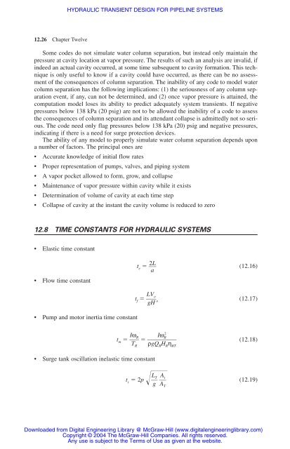
<strong>12</strong>.8 TIME CONSTANTS FOR HYDRAULIC SYSTEMS<br />
• Elastic time constant<br />
• Flow time constant<br />
HYDRAULIC TRANSIENT DESIGN FOR PIPELINE SYSTEMS<br />
• Pump and motor inertia time constant<br />
te � � 2L<br />
�<br />
a<br />
tf � � LVo<br />
gH<br />
• Surge tank oscillation inelastic time constant<br />
� o<br />
(<strong>12</strong>.16)<br />
(<strong>12</strong>.17)<br />
tm � � I<br />
2<br />
ωR<br />
IωR<br />
� ��� (<strong>12</strong>.18)<br />
T ρgQ H<br />
R<br />
t s � 2p �� L<br />
R<br />
��<br />
g� T At<br />
���� AT<br />
R η RT<br />
(<strong>12</strong>.19)<br />
Downloaded from Digital Engineering Library @ McGraw-Hill (www.digitalengineeringlibrary.com)<br />
Copyright © 2004 The McGraw-Hill Companies. All rights reserved.<br />
Any use is subject to the Terms of Use as given at the website.


