

chapter 12 hydraulic transient design for pipeline systems
chapter 12 hydraulic transient design for pipeline systems
chapter 12 hydraulic transient design for pipeline systems

Create successful ePaper yourself
Turn your PDF publications into a flip-book with our unique Google optimized e-Paper software.
HYDRAULIC TRANSIENT DESIGN FOR PIPELINE SYSTEMS<br />
Hydraulic Transient Design <strong>for</strong> Pipeline Systems <strong>12</strong>.13<br />
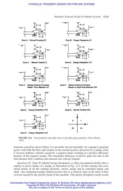
FIGURE <strong>12</strong>.6 Four quadrants and eight zones of possible pump operation. (From Martin,<br />
1983)<br />
<strong>transient</strong> caused by power failure. It is possible, but not desirable, <strong>for</strong> a pump to generate<br />
power with both the flow and rotation in the normal positive direction <strong>for</strong> a pump, Zone<br />
C (reverse turbine), whichis caused by a negative head, resulting in a positive efficiency<br />
because of the negative torque. The maximum efficiency would be quite low due to the<br />
bad entrance flow condition and unusual exit velocity triangle.<br />
Quadrant IV. Zone H, labeled energy dissipation, is often encountered shortly after a<br />
tripout or power failure of a pump, as illustrated in Fig. <strong>12</strong>.5. In this instance the combined<br />
inertia of all the rotating elements—motor, pump and its entrained liquid, and<br />
shaft—has maintained pump rotation positive but at a reduced value at the time of flow<br />
reversal caused by the positive head on the machine. This purely dissipative mode results<br />
Downloaded from Digital Engineering Library @ McGraw-Hill (www.digitalengineeringlibrary.com)<br />
Copyright © 2004 The McGraw-Hill Companies. All rights reserved.<br />
Any use is subject to the Terms of Use as given at the website.


