

chapter 12 hydraulic transient design for pipeline systems
chapter 12 hydraulic transient design for pipeline systems
chapter 12 hydraulic transient design for pipeline systems

Create successful ePaper yourself
Turn your PDF publications into a flip-book with our unique Google optimized e-Paper software.
<strong>12</strong>.16 Chapter Twelve<br />
HYDRAULIC TRANSIENT DESIGN FOR PIPELINE SYSTEMS<br />
the standpoint of physical understanding, are fraught with the difficulty of |v/α| becoming<br />
infinite as the unit passes through, or remains at, zero speed (� = 0). Some have solved<br />
that problem by switching from h/α 2 versus v/α to h/v 2 versus α/v, and likewise <strong>for</strong> β, <strong>for</strong><br />
|v/α| � l. This technique doubles the number of curves on Figs. <strong>12</strong>.7 and <strong>12</strong>.8, and thereby<br />
creates discontinuities in the slopes of the lines at |v/α| � 1, in addition to complicating<br />
the storing and interpolation of data. Marchal et al. (1965) devised a useful trans<strong>for</strong>mation<br />
which allowed the complete pump characteris-tics to be represented by two single<br />
curves, as shown <strong>for</strong> the same pump in Fig. <strong>12</strong>.10. The difficulty of v/α becoming infinite<br />
was eliminated by utilizing the function tan �1 (v/α) as the abscissa. The eight zones, or<br />
four quadrants can then be connected by the continuous functions. Although some of the<br />
physical interpretation of pump data has been lost in the trans<strong>for</strong>mation, Fig. <strong>12</strong>.10 is now<br />
a preferred correlation <strong>for</strong> <strong>transient</strong> analysis using a digital computer because of function<br />
continuity and ease of numerical interpolation. The singularities in Figs. <strong>12</strong>.7 and <strong>12</strong>.8 and<br />
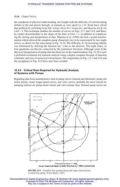
the asymptotes in Fig. <strong>12</strong>.9 have now been avoided.<br />
<strong>12</strong>.4.5 Critical Data Required <strong>for</strong> Hydraulic Analysis<br />
of Systems with Pumps<br />
Regarding data from manufacturers such as pump curves (normal and abnormal), pump and<br />
motor inertia, motor torque-speed curves, and valve curves, probably the most critical <strong>for</strong><br />
pumping stations are pump-motor inertia and valve closure time. Normal pump curves are<br />
FIGURE <strong>12</strong>.9 Complete four-quadrant head and torque characteristics<br />
of radial-flow pump. (From Martin, 1983)<br />
Downloaded from Digital Engineering Library @ McGraw-Hill (www.digitalengineeringlibrary.com)<br />
Copyright © 2004 The McGraw-Hill Companies. All rights reserved.<br />
Any use is subject to the Terms of Use as given at the website.


