

chapter 12 hydraulic transient design for pipeline systems
chapter 12 hydraulic transient design for pipeline systems
chapter 12 hydraulic transient design for pipeline systems

Create successful ePaper yourself
Turn your PDF publications into a flip-book with our unique Google optimized e-Paper software.
HYDRAULIC TRANSIENT DESIGN FOR PIPELINE SYSTEMS<br />
Hydraulic Transient Design <strong>for</strong> Pipeline Systems <strong>12</strong>.19<br />
combat the downsurge problem there are a number of options, mostly involving the <strong>design</strong><br />
and installation of one or more surge protection devices. In this section various surge protection<br />
techniques will be discussed, followed by an assessment of the virtue of each with<br />
respect to pumping <strong>systems</strong> in general. The lift <strong>systems</strong> shown in Fig. <strong>12</strong>.11 depict various<br />
surge protection schemes.<br />
<strong>12</strong>.5.1 Critical Parameters <strong>for</strong> Transients<br />
Be<strong>for</strong>e discussing surge protection devices, some comments will be made regarding the<br />
various <strong>pipeline</strong>, pump and motor, control valve, flow rate, and other parameters that<br />
affect the magnitude of the <strong>transient</strong>. For a pumping system the four main parameters are<br />
(1) pump flow rate, (2) pump and motor WR 2 , (3) any valve motion, and (4) <strong>pipeline</strong> characteristics.<br />
The <strong>pipeline</strong> characteristics include piping layout—both plan and profile—<br />
pipe size and material, and the acoustic velocity. So-called short <strong>systems</strong> respond differently<br />
than long <strong>systems</strong>. Likewise, valve motion and its effect, whether controlled valves<br />
or check valves, will have different effects on the two types of <strong>systems</strong>.<br />
The <strong>pipeline</strong> characteristics—item number (4)—relate to the response of the system to<br />
a <strong>transient</strong> such as pump power failure. Clearly, the response will be altered by the addition<br />
of one or more surge protection device or the change of (1) the flow rate, or (2) the<br />
WR 2 , or (3) the valve motion. Obviously, <strong>for</strong> a given pipe network and flow distribution<br />
there are limited means of controlling <strong>transient</strong>s by (2) WR 2 and (3) valve actuation. If<br />
these two parameters can not alleviate the problem than the <strong>pipeline</strong> response needs to be<br />
altered by means of surge protection devices.<br />
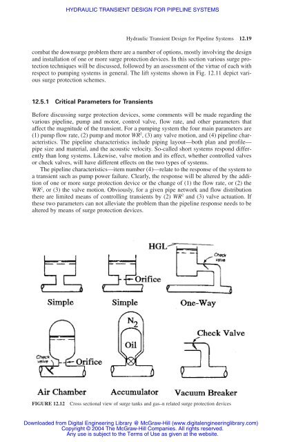
FIGURE <strong>12</strong>.<strong>12</strong> Cross sectional view of surge tanks and gas–n related surge protection devices<br />
Downloaded from Digital Engineering Library @ McGraw-Hill (www.digitalengineeringlibrary.com)<br />
Copyright © 2004 The McGraw-Hill Companies. All rights reserved.<br />
Any use is subject to the Terms of Use as given at the website.


