chapter 12 hydraulic transient design for pipeline systems
chapter 12 hydraulic transient design for pipeline systems
chapter 12 hydraulic transient design for pipeline systems
You also want an ePaper? Increase the reach of your titles
YUMPU automatically turns print PDFs into web optimized ePapers that Google loves.
HYDRAULIC TRANSIENT DESIGN FOR PIPELINE SYSTEMS<br />
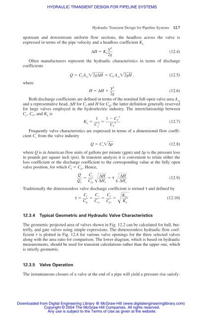
upstream and downstream uni<strong>for</strong>m flow sections, the headloss across the valve is<br />
expressed in terms of the pipe velocity and a headloss coefficient K L<br />
2<br />
∆H � K<br />
V<br />
L�� (<strong>12</strong>.4)<br />
2g<br />
Often manufacturers represent the <strong>hydraulic</strong> characteristics in terms of discharge<br />
coefficients<br />
Q � Cf Avo�2�g�∆�H� � CF Avo�2�g�H� , (<strong>12</strong>.5)<br />
where<br />
2<br />
H � ∆H �<br />
V<br />
�� 2g<br />
(<strong>12</strong>.6)<br />
Both discharge coefficients are defined in terms of the nominal full-open valve area Avo and a representative head, ∆H <strong>for</strong> Cf and H <strong>for</strong> CQ , the latter definition generally reserved<br />
<strong>for</strong> large valves employed in the hydroelectric industry. The interrelationship between<br />
Cf , CF , and KL is<br />
2<br />
1 1 � CF KL � �<br />
C 2� � �� 2<br />
C f<br />
F<br />
(<strong>12</strong>.7)<br />
Frequently valve characteristics are expressed in terms of a dimensional flow coefficient<br />
Cv from the valve industry<br />
Q � C v �∆�p� (<strong>12</strong>.8)<br />
where Q is in American flow units of gallons per minute (gpm) and ∆p is the pressure loss<br />
in pounds per square inch (psi). In <strong>transient</strong> analysis it is convenient to relate either the<br />
loss coefficient or the discharge coefficient to the corresponding value at the fully open<br />
valve position, <strong>for</strong> which C f � C fo . Hence,<br />
Q Cf<br />
�� � �� Qo<br />
C � fo<br />
� ∆H<br />
�H ∆���<br />
o<br />
� τ �� ∆H<br />
�H ∆���<br />
o<br />
(<strong>12</strong>.9)<br />
Traditionally the dimensionless valve discharge coefficient is termed τ and defined by<br />
Cf<br />
Cv<br />
Cf<br />
τ � �� � �� � �� �� C C C<br />
�K<br />
o<br />
(<strong>12</strong>.10)<br />
fo<br />
<strong>12</strong>.3.4 Typical Geometric and Hydraulic Valve Characteristics<br />
vo<br />
The geometric projected area of valves shown in Fig. <strong>12</strong>.2 can be calculated <strong>for</strong> ball, butterfly,<br />
and gate valves using simple expressions. The dimensionless <strong>hydraulic</strong> flow coefficient<br />
� is plotted in Fig. <strong>12</strong>.4 <strong>for</strong> various valve openings <strong>for</strong> the three selected valves<br />
along with the area ratio <strong>for</strong> comparison. The lower diagram, which is based on <strong>hydraulic</strong><br />
measurements, should be used <strong>for</strong> <strong>transient</strong> calculations rather than the upper one, which<br />
is strictly geometric.<br />
<strong>12</strong>.3.5 Valve Operation<br />
Hydraulic Transient Design <strong>for</strong> Pipeline Systems <strong>12</strong>.7<br />
The instantaneous closure of a valve at the end of a pipe will yield a pressure rise satisfy-<br />
Downloaded from Digital Engineering Library @ McGraw-Hill (www.digitalengineeringlibrary.com)<br />
Copyright © 2004 The McGraw-Hill Companies. All rights reserved.<br />
Any use is subject to the Terms of Use as given at the website.<br />
fo<br />
��<br />
K� L<br />
L


