Datascope - Mindray
Datascope - Mindray
Datascope - Mindray

Create successful ePaper yourself
Turn your PDF publications into a flip-book with our unique Google optimized e-Paper software.
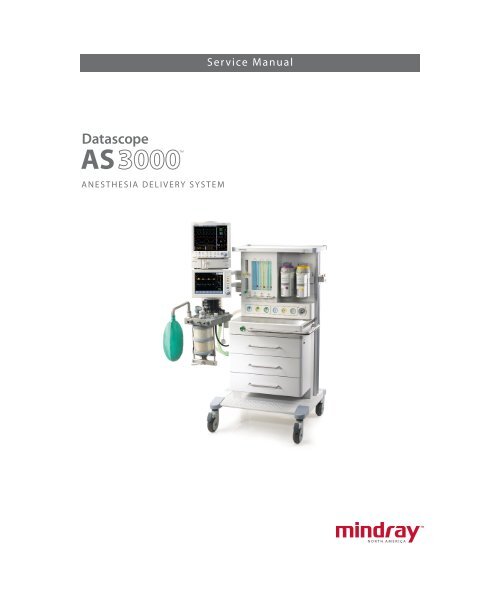
<strong>Datascope</strong><br />
AS<br />
AnesthesiA Delivery system<br />
<br />
service manual
<strong>Datascope</strong><br />
AS<br />
AnesthesiA Delivery system<br />
<br />
service manual
AS3000 is a U.S. trademark of <strong>Mindray</strong> DS USA, Inc.<br />
Krytox ® is a U.S. registered trademark of E. I. du Pont de Nemours and Company<br />
Selectatec ® is a U.S. trademark of Datex Ohmeda<br />
Glyptal ® is a U.S. registered trademark of Glyptal, Inc.<br />
Dräger Vapor ® and plug-in system S-2000 are registered trademarks of Dräger Medical.<br />
Copyright © <strong>Mindray</strong> DS USA, Inc., 2008. All rights reserved. Contents of this publication may not be reproduced in any<br />
form without permission of <strong>Mindray</strong> DS USA, Inc.<br />
AS3000 Service Manual 0070-10-0683
Table of Contents<br />
Foreword.......................................................................................................................................................vii<br />
Warnings, Cautions and Notes ........................................................................................................................vii<br />
Warnings ......................................................................................................................................................vii<br />
Cautions .......................................................................................................................................................viii<br />
Notes ............................................................................................................................................................ ix<br />
Theory of Operation .....................................................................................................1 - 1<br />
Introduction................................................................................................................................................ 1 - 1<br />
Microprocessor-controlled Ventilator.............................................................................................................. 1 - 2<br />
Components............................................................................................................................................... 1 - 3<br />
Front View .......................................................................................................................................... 1 - 3<br />
Side View........................................................................................................................................... 1 - 5<br />
Rear View........................................................................................................................................... 1 - 7<br />
Other components (not identified in graphics) ......................................................................................... 1 - 8<br />
Breathing System................................................................................................................................. 1 - 9<br />
The Ventilator Unit ............................................................................................................................... 1 - 9<br />
Adjustable Alarms ............................................................................................................................. 1 - 10<br />
Compliance Compensation................................................................................................................. 1 - 10<br />
Electrical Supply ....................................................................................................................................... 1 - 11<br />
Electrical components......................................................................................................................... 1 - 11<br />
Ventilator Control and Drive....................................................................................................................... 1 - 12<br />
BDU (Basic Digital Unit)...................................................................................................................... 1 - 12<br />
Amplifier Board ........................................................................................................................ 1 - 14<br />
Drive Gas Pressure Sensor Board ................................................................................................ 1 - 19<br />
PAW Pressure Sensor Board....................................................................................................... 1 - 20<br />
Breathing System Heater ............................................................................................................ 1 - 21<br />
Sensor Board............................................................................................................................ 1 - 23<br />
Power Management........................................................................................................................... 1 - 26<br />
Battery ............................................................................................................................................. 1 - 28<br />
Power Supply.................................................................................................................................... 1 - 28<br />
Anesthesia System Components .................................................................................................................. 1 - 29<br />
Auxiliary Outlets................................................................................................................................ 1 - 29<br />
Absorber Heater Wire Board.............................................................................................................. 1 - 29<br />
Work Light Board .............................................................................................................................. 1 - 29<br />
Ventilator UI ............................................................................................................................................. 1 - 31<br />
Keyboard Board................................................................................................................................ 1 - 31<br />
Display............................................................................................................................................. 1 - 34<br />
Communication Interface / RS232 Isolate Board ...................................................................................1 - 35<br />
Fuses ............................................................................................................................................... 1 - 35<br />
Ventilator Pneumatic - O 2 Drive Gas ........................................................................................................... 1 - 36<br />
Ventilator pneumatic drive .................................................................................................................. 1 - 36<br />
Drive Pressure-High pressure regulator ................................................................................................. 1 - 36<br />
Gas Box Assembly............................................................................................................................. 1 - 36<br />
Tube color coding.............................................................................................................................. 1 - 36<br />
The Breathing System ................................................................................................................................ 1 - 37<br />
CMV mode, inspiration ...................................................................................................................... 1 - 37<br />
CMV mode, expiration....................................................................................................................... 1 - 37<br />
Manual mode, inspiration................................................................................................................... 1 - 38<br />
Manual mode, expiration ................................................................................................................... 1 - 38<br />
Pneumatic PEEP ................................................................................................................................. 1 - 39<br />
Ventilator in Standby.......................................................................................................................... 1 - 39<br />
Breathing System Components ............................................................................................................ 1 - 39<br />
Ventilation Bellows System.......................................................................................................... 1 - 39<br />
AS3000 Service Manual 0070-10-0683 i
Table of Contents<br />
Manual Breathing Bag............................................................................................................... 1 - 39<br />
CO 2 Absorber .......................................................................................................................... 1 - 39<br />
Inspiratory and Expiratory Valves ................................................................................................ 1 - 39<br />
APL (Airway Pressure Limiting) valve ............................................................................................ 1 - 39<br />
Installation Guide .........................................................................................................2 - 1<br />
Delivery of The New Anesthesia Machine ...................................................................................................... 2 - 1<br />
Assembly ................................................................................................................................................... 2 - 2<br />
Unpacking.......................................................................................................................................... 2 - 2<br />
Breathing System and Breathing System Accessories ................................................................................ 2 - 2<br />
Attaching the Mounting Arms and User Interface............................................................................. 2 - 3<br />
Breathing System Connections ...................................................................................................... 2 - 3<br />
Anesthesia System Connections..................................................................................................... 2 - 3<br />
Tank Wrench and Pre-operation Checklist............................................................................................... 2 - 4<br />
Patient Suction Regulator and Arm......................................................................................................... 2 - 4<br />
Suction Canister Bracket....................................................................................................................... 2 - 4<br />
Utility Tray, Monitor Mounting Arm with Utility Hook(s)............................................................................. 2 - 4<br />
Vaporizers.......................................................................................................................................... 2 - 4<br />
High Pressure Hoses ............................................................................................................................ 2 - 5<br />
Emergency Cylinder(s) ......................................................................................................................... 2 - 5<br />
Breathing Circuit, CO2 Absorbent, and Liquid Vaporizer Agent ................................................................ 2 - 5<br />
Monitoring Products - Mounting and Electrical Connection........................................................................2 - 6<br />
Agent Monitor Waste Gas Scavenging .................................................................................................. 2 - 6<br />
Oxygen Sensor Calibration .................................................................................................................. 2 - 6<br />
Installation Checkout Procedure .................................................................................................................... 2 - 8<br />
Repair Information .......................................................................................................3 - 1<br />
Introduction................................................................................................................................................ 3 - 1<br />
Warnings and Cautions............................................................................................................................... 3 - 2<br />
Warnings ........................................................................................................................................... 3 - 2<br />
Cautions............................................................................................................................................. 3 - 2<br />
Troubleshooting Guidelines .......................................................................................................................... 3 - 2<br />
Special Tools Required ................................................................................................................................ 3 - 3<br />
Troubleshooting Chart ................................................................................................................................. 3 - 4<br />
Common Symptoms and Corrective Actions for Field Service Technicians ................................................... 3 - 4<br />
Leak Troubleshooting................................................................................................................................. 3 - 11<br />
Test Pneumatics ........................................................................................................................................ 3 - 12<br />
Leak Test - Manual Ventilation Test....................................................................................................... 3 - 12<br />
Safety Valve Test ............................................................................................................................... 3 - 13<br />
Leak Test - Automatic Ventilation Test.................................................................................................... 3 - 14<br />
Compliance Test................................................................................................................................ 3 - 15<br />
Pneumatic Hose and Wiring Diagrams ........................................................................................................ 3 - 16<br />
Pneumatic Hose Labeling.................................................................................................................... 3 - 16<br />
Sampling Pipeline Module Interface Labeling ........................................................................................ 3 - 17<br />
Electrical Cable Labeling .................................................................................................................... 3 - 18<br />
Replacement Parts and Accessories...............................................................................4 - 1<br />
Introduction................................................................................................................................................ 4 - 1<br />
Available Replacement Parts and Sub-Assemblies ........................................................................................... 4 - 1<br />
Exchange Program .............................................................................................................................. 4 - 1<br />
Replacement Parts Pricing Information .................................................................................................... 4 - 1<br />
Ordering Information ........................................................................................................................... 4 - 2<br />
Isometric Drawings...................................................................................................................................... 4 - 3<br />
Chassis .............................................................................................................................................. 4 - 3<br />
Chassis Parts List ......................................................................................................................... 4 - 5<br />
ii 0070-10-0683 AS3000 Service Manual
Table of Contents<br />
Breathing System................................................................................................................................. 4 - 6<br />
Breathing System Parts List.......................................................................................................... 4 - 11<br />
Electric Box....................................................................................................................................... 4 - 12<br />
Electric Box Parts List.................................................................................................................. 4 - 12<br />
Gas Circuit Box................................................................................................................................. 4 - 13<br />
Gas Circuit Box Parts List............................................................................................................ 4 - 13<br />
User Interface.................................................................................................................................... 4 - 14<br />
User Interface Parts List............................................................................................................... 4 - 15<br />
Flowmeter......................................................................................................................................... 4 - 16<br />
Flowmeter Parts List.................................................................................................................... 4 - 16<br />
Calibration ...................................................................................................................5 - 1<br />
Introduction................................................................................................................................................ 5 - 1<br />
Calibration Warnings, Precautions, and Notes............................................................................................... 5 - 2<br />
Warnings ........................................................................................................................................... 5 - 2<br />
Cautions............................................................................................................................................. 5 - 2<br />
Notes................................................................................................................................................. 5 - 3<br />
General Guidelines..................................................................................................................................... 5 - 4<br />
Test Equipment and Special Tools Required.................................................................................................... 5 - 4<br />
Calibration Procedures ................................................................................................................................ 5 - 4<br />
Oxygen Sensor Calibration .................................................................................................................. 5 - 4<br />
Proportional Valve Regulator Calibration ................................................................................................ 5 - 6<br />
Flow Sensor Calibration ....................................................................................................................... 5 - 7<br />
Flow Valve Calibration......................................................................................................................... 5 - 9<br />
Paw Sensor....................................................................................................................................... 5 - 10<br />
PEEP Valve ....................................................................................................................................... 5 - 11<br />
Flow Meter ....................................................................................................................................... 5 - 12<br />
Leakage detection.............................................................................................................................. 5 - 13<br />
Startup leakage detection........................................................................................................... 5 - 13<br />
APL Valve leakage detection....................................................................................................... 5 - 13<br />
Safety Valve leakage detection ................................................................................................... 5 - 13<br />
Breathing System leakage detection............................................................................................. 5 - 13<br />
Compliance detection ........................................................................................................................ 5 - 13<br />
Periodic Maintenance....................................................................................................6 - 1<br />
Maintenance Schedule ................................................................................................................................ 6 - 1<br />
Periodic Maintenance Consumable Parts Kits.................................................................................................. 6 - 1<br />
Periodic Maintenance Schedule of Service Activities........................................................................................ 6 - 2<br />
Visual Inspection Checklist ........................................................................................................................... 6 - 2<br />
Replacement of Consumable Parts................................................................................................................. 6 - 3<br />
Check Valve Cleaning................................................................................................................................. 6 - 4<br />
Tools and Materials ............................................................................................................................. 6 - 4<br />
Cleaning Procedure ............................................................................................................................. 6 - 5<br />
Battery Maintenance and Replacement ........................................................................................................ 6 - 13<br />
Battery Maintenance .......................................................................................................................... 6 - 13<br />
Battery Replacement .......................................................................................................................... 6 - 13<br />
Functional Tests ........................................................................................................................................ 6 - 13<br />
Test Equipment and Special Tools Required........................................................................................... 6 - 13<br />
Pressure Regulator Checks .................................................................................................................. 6 - 14<br />
Proportional Valve Regulator ...................................................................................................... 6 - 14<br />
Gas Delivery System Tests................................................................................................................... 6 - 14<br />
O2 Flush Verification ................................................................................................................. 6 - 14<br />
O2:N2O Ratio System ............................................................................................................... 6 - 15<br />
Start-Up Tests .................................................................................................................................... 6 - 15<br />
AS3000 Service Manual 0070-10-0683 iii
Table of Contents<br />
System Self Test......................................................................................................................... 6 - 15<br />
Leak/Safety Valve Test............................................................................................................... 6 - 15<br />
Leak Test .................................................................................................................................. 6 - 17<br />
Compliance Test ....................................................................................................................... 6 - 20<br />
Manual Leak Test ...................................................................................................................... 6 - 21<br />
Oxygen Sensor Calibration ........................................................................................................ 6 - 22<br />
Pneumatic Leak Tests.......................................................................................................................... 6 - 24<br />
N 2O Cylinder Leak Test ............................................................................................................. 6 - 24<br />
O 2 Cylinder Leak Test................................................................................................................ 6 - 24<br />
AIR Cylinder Leak Test ............................................................................................................... 6 - 24<br />
Line Supply Check Valves Test .................................................................................................... 6 - 24<br />
N 2O Line Pressure Leak Test ....................................................................................................... 6 - 25<br />
O 2 Line Pressure Leak Test.......................................................................................................... 6 - 25<br />
AIR Line Pressure Leak Test ......................................................................................................... 6 - 25<br />
Cylinder Supply Check Valves Test .............................................................................................. 6 - 25<br />
Breathing System Checks.................................................................................................................... 6 - 26<br />
Waste Gas Scavenger Test (if available) ...................................................................................... 6 - 26<br />
Internal Gas Connections Test ..................................................................................................... 6 - 26<br />
Drive Gas Pressure Loss Alarm, N 2O Cutoff Test ........................................................................... 6 - 26<br />
Performance Verification .................................................................................................................... 6 - 27<br />
Standby Mode Ventilation Test.................................................................................................... 6 - 27<br />
Manual Mode Ventilation Test .................................................................................................... 6 - 27<br />
APNEA Alarm Test .................................................................................................................... 6 - 27<br />
Alarm MUTE Test....................................................................................................................... 6 - 27<br />
CMV Adult Ventilation Mode Test................................................................................................ 6 - 28<br />
CMV Child Ventilation Mode Test................................................................................................ 6 - 29<br />
Airway Disconnect Alarm Test..................................................................................................... 6 - 29<br />
PCV Adult Ventilation Mode Test ................................................................................................. 6 - 30<br />
Pressure Support (PS) Ventilation Mode Test.................................................................................. 6 - 31<br />
Alarms and Failsafe Functions ............................................................................................................. 6 - 32<br />
Set Up ..................................................................................................................................... 6 - 32<br />
Low FiO2 Alarm Test.................................................................................................................. 6 - 32<br />
High FiO2 Alarm Test ................................................................................................................ 6 - 33<br />
Peak Pressure Alarms Test .......................................................................................................... 6 - 33<br />
Minute Volume Alarm Test .......................................................................................................... 6 - 34<br />
Miscellaneous Tests............................................................................................................................ 6 - 34<br />
Test the Line Voltage Alarm ........................................................................................................ 6 - 34<br />
Wheel Brakes Test..................................................................................................................... 6 - 34<br />
Work Light Test ......................................................................................................................... 6 - 34<br />
Auxiliary Flowmeter................................................................................................................... 6 - 35<br />
Patient Suction Regulator (if available) ......................................................................................... 6 - 35<br />
Vaporizers........................................................................................................................................ 6 - 35<br />
Vaporizer Interlock Test.............................................................................................................. 6 - 35<br />
Vaporizer Accuracy Test ............................................................................................................ 6 - 36<br />
Vaporizer Leak Test ................................................................................................................... 6 - 36<br />
Dräger Vapor 2000 Operating Instructions ARRB-F001 ................................................................. 6 - 37<br />
Electrical Tests................................................................................................................................... 6 - 38<br />
Convenience AC Outlets Test...................................................................................................... 6 - 38<br />
Electrical Safety Inspection Test ................................................................................................... 6 - 38<br />
AS3000 Installation Checklist ............................................................................................................. 6 - 38<br />
Cleaning.................................................................................................................................................. 6 - 39<br />
Cleaning and Disinfecting the AS3000 ................................................................................................ 6 - 39<br />
iv 0070-10-0683 AS3000 Service Manual
Table of Contents<br />
Cleaning and Sterilizing the Breathing System and Components.............................................................. 6 - 39<br />
Preoperative Checklist ............................................................................................................................... 6 - 39<br />
Phone Numbers and How To Get Assistance................................................................................................ 6 - 47<br />
Warranty .....................................................................................................................7 - 1<br />
Warranty Statements................................................................................................................................... 7 - 1<br />
Disclaimers ................................................................................................................................................ 7 - 2<br />
Product Improvements .......................................................................................................................... 7 - 2<br />
Manufacturer’s Responsibility ....................................................................................................................... 7 - 2<br />
AS3000 Service Manual 0070-10-0683 v
Table of Contents<br />
This page intentionally left blank.<br />
vi 0070-10-0683 AS3000 Service Manual
Foreword Introduction<br />
Foreword<br />
This Service Manual is intended as a guide for technically qualified personnel performing<br />
repair and calibration procedures.<br />
Warnings, Cautions and Notes<br />
Please read and adhere to all warnings, cautions and notes listed here and in the<br />
appropriate areas throughout this manual.<br />
A WARNING is provided to alert the user to potential serious outcomes (death, injury, or<br />
serious adverse events) to the patient or the user.<br />
A CAUTION is provided to alert the user to use special care necessary for the safe and<br />
effective use of the device. They may include actions to be taken to avoid effects on patients<br />
or users that may not be potentially life threatening or result in serious injury, but about which<br />
the user should be aware. Cautions are also provided to alert the user to adverse effects on<br />
this device of use or misuse and the care necessary to avoid such effects.<br />
A NOTE is provided when additional general information is applicable.<br />
Warnings<br />
WARNING: Whenever using anesthetic gases, nitrous oxide, oxygen, or<br />
any hospital gas always follow the appropriate agent<br />
evacuation/collection procedures. Use the hospital gas<br />
evacuation system.<br />
WARNING: For continued protection against fire hazard, replace all<br />
fuses with the specified type and rating.<br />
WARNING: In order to prevent an electric shock, the machine<br />
(protection class I) may only be connected to a correctly<br />
grounded mains connection (socket outlet with grounding<br />
contact).<br />
WARNING: Remove all accessory equipment from the shelf before<br />
moving the anesthesia machine over bumps or on any<br />
inclined surface. Heavy top loading can cause the machine<br />
to tip over causing injury.<br />
WARNING: Possible explosion hazard. Do not operate machine near<br />
flammable anesthetic agents or other flammable<br />
substances. Do not use flammable anesthetic agents (i.e.,<br />
ether or cyclopropane.)<br />
WARNING: The use of anti-static or electrically conductive respiration<br />
tubes, when utilizing high frequency electric surgery<br />
equipment, may cause burns and is therefore not<br />
recommended in any application of this machine.<br />
WARNING: Possible electric shock hazard. The machine may only be<br />
opened by authorized service personnel.<br />
AS3000 Service Manual 0070-10-0683 vii
Introduction Cautions<br />
WARNING: Compressed gasses are considered Dangerous Goods/<br />
Hazardous Materials per I.A.T.A. and D.O.T. regulations. It is<br />
a violation of federal and international law to offer any<br />
package or over pack of dangerous goods for<br />
transportation without the package being appropriately<br />
identified, packed, marked, classified, labeled and<br />
documented according to D.O.T. and I.A.T.A. regulations.<br />
Please refer to the applicable I.A.T.A. Dangerous Goods<br />
Regulations and /or the Code of Federal Regulations 49<br />
(Transportation, Parts 171-180) for further information.<br />
WARNING: Avoid exposure to respiratory gases by always directing<br />
the fresh gas flow from the fresh gas outlet to the waste gas<br />
scavenger.<br />
Cautions<br />
CAUTION: This device uses high pressure compressed gas. When<br />
attaching or disconnecting backup gas cylinders, always<br />
turn the cylinder valves slowly. Use the AS3000 flow meters<br />
to bleed down the pressure, watching the cylinder gauge<br />
indicate the depleting cylinder pressure, before<br />
disconnecting the cylinder from the yoke. Always open and<br />
close cylinder valves fully.<br />
CAUTION: This device operates using compressed gas at high<br />
pressures from the hospital central supply. When connecting<br />
gas supply lines attach the hose connection to the machine<br />
before connecting the quick disconnect fitting to the hospital<br />
source. Disconnect the supply hose from the hospital source<br />
connection prior to disconnecting it from the AS3000 gas<br />
connection fittings.<br />
CAUTION: Refer to the “Periodic Maintenance Schedule of Service<br />
Activities” on page 6-2, in the Periodic Maintenance section<br />
for assistance when performing scheduled periodic<br />
maintenance.<br />
CAUTION: Do not leave gas cylinder valves open if the pipeline supply<br />
is in use and the system master switch is turned to 'ON'. If<br />
used simultaneously, cylinder supplies could be depleted,<br />
leaving an insufficient reserve supply in the event of<br />
pipeline failure.<br />
CAUTION: Use cleaning agent sparingly. Excess fluid could enter the<br />
machine, causing damage.<br />
CAUTION: This machine must only be operated by trained, skilled<br />
medical staff.<br />
CAUTION: Perform the electrical safety inspection as the last step after<br />
completing a repair or after routine maintenance. Perform<br />
this inspection with all covers, panels, and screws installed.<br />
CAUTION: After changing the CO 2 absorbent, carry out a system leak<br />
test.<br />
CAUTION: Only Selectatec compatible vaporizers with Interlock-<br />
System may be used with the AS3000 unit.<br />
CAUTION: After each exchange of a vaporizer, carry out a system Leak<br />
test.<br />
viii 0070-10-0683 AS3000 Service Manual
Notes Introduction<br />
CAUTION: The bellows dome cannot be autoclaved.<br />
CAUTION: Do not clean the machine while it is on and/or plugged in.<br />
CAUTION: Pressing “Quit” at any time during the procedure will cancel<br />
the session's settings and reload the previously-stored<br />
calibration coefficients.<br />
CAUTION: Depleted soda lime changes color. Replace the soda lime if<br />
approximately 2/3 of the absorber content is discolored.<br />
CO 2 absorbent can be safely changed without stopping<br />
mechanical ventilation.<br />
Notes<br />
NOTE: Unauthorized servicing may void the remainder of the<br />
warranty. Check with the factory or with a local authorized<br />
distributor to determine the warranty status of a particular<br />
instrument.<br />
AS3000 Service Manual 0070-10-0683 ix
Introduction Notes<br />
This page intentionally left blank.<br />
x 0070-10-0683 AS3000 Service Manual
1.0 Theory of Operation<br />
1.1 Introduction<br />
The AS3000 is a continuous flow anesthesia system which offers manual or automatic<br />
ventilation, easily adjustable fresh gas delivery, anesthetic agent delivery, ventilation<br />
monitoring, convenient ergonomics, and state-of-the-art safety systems. The components of the<br />
AS3000 Anesthesia System are described this chapter.<br />
AS3000 Service Manual 0070-10-0683 1 - 1
Microprocessor-controlled Ventilator Theory of Operation<br />
1.2 Microprocessor-controlled Ventilator<br />
The Microprocessor-controlled ventilator, with its dedicated Breathing System, allows time-<br />
controlled, pressure limited, constant volume ventilation for all patient groups within a tidal<br />
volume range of 40 mL (4 kg infant) to 1400 mL (large adult).<br />
Time-controlled, pressure limited, and compliance compensated constant volume ventilation<br />
is provided through the Controlled Mandatory Ventilation (CMV) mode. The CMV mode<br />
delivers a viable ventilation method for complicated lung conditions. The ventilator also<br />
provides time-controlled, volume dependant ventilation, targeting a set (adjustable) target<br />
pressure provided through the Pressure Controlled Ventilation (PCV) mode. Automatic and<br />
comprehensive system startup tests and alarm management systems ensure controlled<br />
ventilation conditions in every mode of operation.<br />
The durable and ergonomically designed user interface and Navigator Knob enables easy<br />
operation. The display provides the selected ventilation modes (CMV, PCV, PS and SIMV)<br />
and the following values: Tidal Volume, Peak Pressure, Mean Pressure, FiO2, Breath Rate, I:E<br />
Ratio, PEEP, Plateau Pressure, Alarm limits, and real-time Airway Pressure and flow<br />
waveform.<br />
Patient<br />
Electronic<br />
Control<br />
Exp. Flow<br />
Sensor<br />
Insp. Flow<br />
Sensor<br />
P<br />
Exp. Valve<br />
O2 Sensor<br />
Insp. Valve<br />
Absorber<br />
Canister<br />
Fresh Gas<br />
Breathing Bag<br />
Solenoid<br />
Valve<br />
Reversing<br />
Valve<br />
Vaporizer<br />
Proportional<br />
Valve<br />
Pressure<br />
Regulator<br />
FIGURE 1-1 The AS3000 Pneumatic System<br />
O2<br />
Flush<br />
APL Valve<br />
Bellows<br />
Vaporizer<br />
Exhaust<br />
Valve<br />
PEEP<br />
Valve<br />
Fresh Gas<br />
Flow Sensor<br />
V<br />
Breathing<br />
System<br />
Ventilator<br />
Ratio<br />
Controller<br />
N20<br />
Cuttoff<br />
Gas Inlet<br />
Block<br />
1 - 2 0070-10-0683 AS3000 Service Manual<br />
AGSS<br />
Flow<br />
Tubes<br />
AIR<br />
Flow<br />
Meter<br />
Pressure<br />
Regulator<br />
Pressure<br />
Regulator<br />
Pressure<br />
Regulator<br />
O2<br />
Flow<br />
Meter<br />
O2<br />
Outlet<br />
Pressure<br />
Switch<br />
Inlet Filter<br />
Inlet Filter<br />
Inlet Filter<br />
P<br />
P<br />
P<br />
P<br />
P<br />
P<br />
Cylinder<br />
O O O<br />
Cylinder<br />
Cylinder<br />
N20 AIR O2
Theory of Operation Components<br />
1.3 Components<br />
1.3.1 Front View<br />
1<br />
2<br />
3<br />
4<br />
5<br />
6<br />
7<br />
8<br />
9<br />
FIGURE 1-2 AS3000 Front View<br />
1. Monitor Arm<br />
The Monitor Arm provides support for a bedside monitor. It can easily rotate for more<br />
convenient viewing.<br />
2. User Interface<br />
The display of the user Interface provides waveforms, numeric data and menu tabs. The keys<br />
and Navigator Knob enable the user to power up the system, silence alarms, access menu<br />
tabs, and switch between manual and mechanic ventilation.<br />
AS3000 Service Manual 0070-10-0683 1 - 3<br />
11<br />
10
Components Theory of Operation<br />
3. UI Arm<br />
The UI Arm provides support for the user interface assembly. It can easily rotate for more<br />
convenient viewing.<br />
4. Oxygen Sensor<br />
The Oxygen Sensor monitors the oxygen concentration of the inspired gas of the Breathing<br />
System.<br />
5. Breathing System<br />
The Breathing System’s main function is to store anesthetic gas, oxygen, and air; vent exhaust<br />
gas; and absorb carbon dioxide. It connects directly to the respiratory passage to help<br />
complete the breathing process.<br />
6. CGO (Common Gas Outlet) Subassembly<br />
Mixed gas composed of O2, AIR, N2O, and anesthetic agent connects to the patient's<br />
Breathing System via a flexible tube from the CGO Subassembly.<br />
7. O2 Flush Valve<br />
The O2 Flush Valve is located on the front of the AS3000. The supplied gas does not pass<br />
the flowmeter and vaporizer. It is directly sent to the fresh gas outlet. Press this button to<br />
supply gas (35 - 50 L/min). Release this switch to automatically close the gas supply.<br />
8. AGSS (Anesthetic Gas Scavenging System)<br />
The AGSS (Anesthetic Gas Scavenging System) reclaims exhausted gas generated during<br />
anesthesia.<br />
9. Drawer Subassembly<br />
The AS3000 has three drawers for storage, which can be locked and fixed through the<br />
uppermost drawer lock.<br />
10. Vaporizer Mounting Manifold<br />
The Vaporizer Mounting Manifold provides support for up to two Selectatec ® compatible<br />
anesthetic vaporizers.<br />
11. Flowmeter<br />
The Flowmeter displays gas flow values for N2O, O2, AIR, Auxiliary O2, and Auxiliary AIR.<br />
It consists of coarse and fine flow tubes used to accurately measure gas flow with additional<br />
flow tubes to measure auxiliary O2 and AIR gas flow.<br />
Flow tube measurement values:<br />
GAS FINE FLOW TUBE<br />
COARSE FLOW TUBE<br />
-01 UNITS -02 UNITS AUXILIARY FLOW TUBE<br />
N2O 0 - 1 L/min 1 - 12 L/min 1 - 10 L/min N/A<br />
O2 0 - 1 L/min 1 - 10 L/min 1 - 10 L/min 0 - 15 L/min<br />
AIR 0 - 1 L/min 1 - 15 L/min 1 - 12 L/min 0 - 15 L/min<br />
1 - 4 0070-10-0683 AS3000 Service Manual
Theory of Operation Components<br />
1.3.2 Side View<br />
12<br />
13<br />
14<br />
15<br />
16<br />
17<br />
18<br />
19<br />
20<br />
21<br />
22<br />
23<br />
FIGURE 1-3 AS3000 Side View<br />
12. Upper Mainframe Subassembly<br />
The Upper Mainframe Subassembly provides support for the pressure gauges, the Flowmeter,<br />
the gas box assembly, the mains supply assembly, and the YOKE assembly.<br />
13. User Interface Cable<br />
The User Interface Cable provides signal transmission between the User Interface and the<br />
main unit.<br />
AS3000 Service Manual 0070-10-0683 1 - 5
Components Theory of Operation<br />
14. Auxiliary Gas Outlet Assembly<br />
The Auxiliary Gas Outlet Assembly provides the patient with auxiliary oxygen and air mixtures<br />
(of different concentrations). It also contains an O2 connection for use with other equipment.<br />
15. Breathing System Interface<br />
The Breathing System Interface provides a connection interface for gas signal acquisition<br />
between the Breathing System and gas circuit.<br />
16. Breathing System Pneumatic Hose<br />
The Breathing System Pneumatic Hose provides multiple connections including: PEEP control,<br />
Auto/Manual control, and four pressure sampling connections between the Breathing System<br />
and mainframe.<br />
17. O2 Sensor Cable<br />
The O2 Sensor Cable provides a connection between the oxygen sensor component in the Breathing<br />
System and the oxygen concentration signal acquisition port on outlet module of the mainframe.<br />
18. Breathing System Interface<br />
The Breathing System Interface provides the main unit with an interface for connection with<br />
drive gas, heating system and the oxygen concentration sensor of the Breathing System.<br />
19. The Breathing System Support Arm<br />
The Breathing System Support Arm provides connection between the Breathing System and<br />
the mainframe, in order to support the Breathing System.<br />
20. Heater Wire<br />
The Heater Wire provides connection to the heating system of the Breathing System. By<br />
heating the Breathing System during anesthesia, accumulation of water in the Breathing<br />
System is minimized. It also provides comfortable gas to the patient.<br />
21. AGSS Transfer Hose<br />
The AGSS Transfer Hose provides pipeline connection between the exhaust gas outlet of the<br />
Breathing System and the AGSS evacuation system.<br />
22. Lower Mainframe Assembly<br />
The Lower Mainframe Assembly provides support for the drawer subassembly, outlet module,<br />
CGO subassembly, O2 flush valve and the electric box. Together with the Upper Mainframe<br />
Subassembly and Base Assembly, forms the mainframe of the machine.<br />
23. Base Assembly<br />
The Base Assembly provides support to the whole machine. The four casters provide<br />
movement for the machine in any direction. The front casters have a locking function.<br />
1 - 6 0070-10-0683 AS3000 Service Manual
Theory of Operation Components<br />
1.3.3 Rear View<br />
24<br />
25<br />
26<br />
27<br />
28<br />
29<br />
30<br />
31<br />
32<br />
33<br />
FIGURE 1-4 AS3000 Rear View<br />
24. Top Shelf Assembly<br />
The Top shelf Assembly includes the work light and its switch. It also serves as a storage<br />
area.<br />
25. Gas Input Assembly<br />
The Gas Input Assembly allows gas in the pipeline and backup gas cylinder to enter the<br />
AS3000 for regulation. The Pressure regulator reduces pressure to 36 psi (250 kPa). The<br />
O2 operated valve can open allowing N2O to enter the flowmeter only when O2 pressure is<br />
above 7.3 psi (50 kPa). Otherwise, N2O cannot enter the gas circuit. The pressure switch<br />
generates a signal when the input pressure is below 29 psi (200 kPa), and the system will<br />
provide an audible alarm.<br />
AS3000 Service Manual 0070-10-0683 1 - 7
Components Theory of Operation<br />
26. Vaporizer Storage Mount<br />
The Vaporizer Storage Mount provides the AS3000 with auxiliary placement for a<br />
vaporizer.<br />
27. Mains Supply Assembly<br />
The Mains Supply Assembly attaches the AS3000 to an external AC wall outlet. It also<br />
supplies power throughout the unit.<br />
28. Electronic Flowmeter Assembly<br />
The Electronic Flowmeter Assembly provides fresh gas flow measurement for the AS3000.<br />
29. Gas Box Assembly<br />
The Gas Box Assembly provides drive gas to the Breathing System and includes a safety<br />
valve to insure that pressure stays below 85 cmH2O. It also contains the PEEP valve, and the<br />
differential pressure sensors.<br />
30. YOKE Assembly<br />
The YOKE Assembly provides connection for three backup gas cylinders. The pressure<br />
regulator for the backup gas cylinder reduces the pressure of a high pressure gas cylinder<br />
down to 43.5 psi (300 kPa).<br />
31. AMP Cables<br />
The AMP Cables provide signal transmission between the electric box and gas circuit box.<br />
32. Electric Box Assembly<br />
The Electric Box Assembly provides, and distributes power to the AS3000.<br />
33. Rear Panel Assembly<br />
The Rear Panel Assembly protects, and provides heat dissipation for the electric box and<br />
auxiliary support for the backup gas cylinder.<br />
1.3.4 Other components (not identified in graphics)<br />
34. Inspiratory and Expiratory Valves<br />
The Inspiratory and Expiratory Valves are unidirectional valves that allow air to flow in only<br />
one direction.<br />
35. Absorber Canister<br />
The AS3000 uses two Absorber Canisters which can contain 1500 mL of soda lime each.<br />
They can be used for 6 - 8 hours each if full. Water generated from the reaction with CO2 is<br />
drained from a valve on the lower side of the canister.<br />
36. APL (Airway Pressure Limiting) Valve<br />
The APL Valve is used for limiting maximum airway pressure during manual ventilation. The<br />
adjustable range of the APL is 0 - 70 cmH2O. 1 - 8 0070-10-0683 AS3000 Service Manual
Theory of Operation Components<br />
37. Bellows Assembly<br />
The AS3000 employs ascending ventilation bellows, in which mixed gas is stored. Drive<br />
gas supplied by the ventilator forces the bellows to descend sending mixed gas into the<br />
inspiratory passage of patient's airway. If a patient's airway suffers from gas leakage, the<br />
bellows will collapse, informing the operator of a possible problem. A tidal volume scale is<br />
provided on the transparent dome, through which a patient's tidal volume can be estimated.<br />
38. Pressure-relief Valve<br />
The Pressure-relief Valve is located at the base of the bellows. When end-expiration airway<br />
pressure reaches 1 - 3 cmH2O, the pressure-relief valve opens and redundant gas is<br />
expelled.<br />
39. Exhaust Gas Outlet<br />
The Exhaust Gas Outlet is located on the lower part of the Breathing System. It is connected<br />
to the AGSS or via the AGSS transfer tube.<br />
40. Absorber Heating System<br />
The Breathing System is heated to body temperature to avoid humidified gases condensing<br />
within the Breathing System thus improving airway climatization for the patient's re-breathing<br />
of respiratory gases.<br />
1.3.5 Breathing System<br />
The Breathing System is integrated into a compact aluminum block. This block is heated to<br />
body temperature to prevent condensing of humidified gases within the Breathing System,<br />
thus improving airway climatization for the patient's re-breathing of respiratory gases. The<br />
heated Breathing System contains: an inspiratory valve with O2 adapter for FiO2 measurement, expiratory valve, APL Valve, breathing bag connection, and internal<br />
inspiratory and expiratory flow sensors.<br />
1.3.6 The Ventilator Unit<br />
The AS3000 ventilator offers multiple ventilation modes: Controlled Mandatory Ventilation<br />
with volume control (CMV), Pressure Control Ventilation (PCV), Synchronized Intermittent<br />
Mandatory Ventilation (SIMV), and Pressure Support (PS) ventilation. Electronic PEEP is<br />
available in all ventilation modes. User control over inspiratory flow (SLOPE) is possible in<br />
PCV, SIMV, and PS modes. Automatic fresh gas compensation limits the effect of user<br />
changes in fresh gas flow rate on the patient. The traditional bellows system is driven by<br />
oxygen and makes patient disconnections clearly visible.<br />
AS3000 Service Manual 0070-10-0683 1 - 9
Components Theory of Operation<br />
1.3.7 Adjustable Alarms<br />
Minimum and maximum alarm limits can be set for Peak Pressure, Mean Pressure and FiO 2 .<br />
Minimum alarm limits can be set for Tidal Volume and Minute Volume. Exceeding the peak<br />
pressure alarm limit automatically halts the inspiratory phase preventing airway pressure<br />
from exceeding the high alarm setting. In the CMV mode, when reaching this pressure limit,<br />
a “High Airway Pressure” alarm is displayed, and inspiration is discontinued. The next<br />
inspiration occurs at the regular time interval, preventing increase of the respiratory rate. The<br />
result is a decreased tidal volume (T Vol.) and minute volume (M Vol.). During pressure<br />
limitation, the ventilator displays the alarm message until the condition is corrected.<br />
1.3.8 Compliance Compensation<br />
Compliance compensation automatically corrects for the expansion of the circuit in CMV<br />
ventilation mode. System compliance is measured by the ventilator to maintain the set tidal<br />
volume (±15%). The compliance test may be bypassed at machine power up. When<br />
bypassing the compliance test, the default settings are used.<br />
1 - 10 0070-10-0683 AS3000 Service Manual
Theory of Operation Electrical Supply<br />
1.4 Electrical Supply<br />
1.4.1 Electrical components<br />
Probe Flow<br />
Airway Pressure<br />
FiO2 Sensor<br />
10.4” TFT-LCD<br />
Gas Source Pressure<br />
PC104<br />
Ventilator UI<br />
Ventilator Control and Drive<br />
BDU<br />
Amplifier<br />
P. Val. Insp.<br />
FIGURE 1-5 Electrical Components Overview<br />
Manual/Mech Val.<br />
Cal. Valve<br />
FM Flow Sensor<br />
Cable<br />
Flow Insp.<br />
Val. Exp. PEEP<br />
Backlight Inverter<br />
Amplifier for<br />
audio alarm<br />
Communication<br />
and Interface<br />
PWR MNG<br />
Anesthesia<br />
AS3000 Service Manual 0070-10-0683 1 - 11<br />
DA<br />
Internal Signals<br />
Pwr<br />
BAT<br />
DC/DC<br />
PS<br />
AC/DC<br />
Keypad<br />
Knob<br />
Switch<br />
Switch<br />
Work Light<br />
SW<br />
Ctrl &<br />
Protect<br />
Power Supply<br />
FM Back Light<br />
AC Heater<br />
Inlet<br />
Filter<br />
Aux Mains<br />
Outlet
Ventilator Control and Drive Theory of Operation<br />
1.5 Ventilator Control and Drive<br />
1.5.1 BDU (Basic Digital Unit)<br />
The BDU serves as the active ventilator control. The BDU controls the actions of the PEEP,<br />
calibration, and proportional valves, and reads the signal flow, and pressure sensors and<br />
valves<br />
FIGURE 1-6 BDU Control Board, Top View<br />
1 - 12 0070-10-0683 AS3000 Service Manual
Theory of Operation Ventilator Control and Drive<br />
FIGURE 1-7 BDU Control Board, Bottom View<br />
AS3000 Service Manual 0070-10-0683 1 - 13
Ventilator Control and Drive Theory of Operation<br />
1.5.1.1 Amplifier Board<br />
FIGURE 1-8 Amplifier Board, Top View<br />
FIGURE 1-9 Amplifier Board, Bottom View<br />
1 - 14 0070-10-0683 AS3000 Service Manual
Theory of Operation Ventilator Control and Drive<br />
O 2 Sensor Input, S4<br />
PIN NAME FUNCTION<br />
1. O2- O2 Sensor Input -<br />
2. O2- O2 Sensor Input -<br />
3. O2+ O2 Sensor Input +<br />
4. O2 + O2 Sensor Input +<br />
DC Power Input, J7<br />
PIN NAME FUNCTION<br />
1. GND Power Ground<br />
2. +5V Controller Logic Power<br />
3. P12V Power 12V<br />
4. PWBUS Power Bus 24V<br />
5. GND Analog Ground<br />
6. A12V Analog 12V<br />
7. 5V/4.8V Power 5V/4.8V<br />
Power Control, J20<br />
PIN NAME FUNCTION<br />
1. GND Ground<br />
2. /PWON Power On Enable, Low active<br />
3. PWEN Power On Enable, High active<br />
4. 5VAUX 5V Auxiliary<br />
5. DC_M AC/DC Monitor signal<br />
6. PWBUS Power bus<br />
7. BAT_M Battery Monitor signal<br />
8. APE Auxiliary Power Enable<br />
9. CHAR_SIGNAL Charge Status, No connection<br />
10. /MUTE Mute, No connection<br />
Signals and Power to Keyboard, J5<br />
PIN NAME FUNCTION<br />
1. ENPW Power Enable, High active<br />
2. /PWON / Power on Enable, Low active<br />
3. 5VAUX 5V Auxiliary<br />
4. APE Auxiliary Power Enable<br />
5. GND Ground<br />
6. TTLRX TTL Receive<br />
7. 232ARX RS232A Receive<br />
8. 232BRX RS232B Receive<br />
9. GND Ground<br />
AS3000 Service Manual 0070-10-0683 1 - 15
Ventilator Control and Drive Theory of Operation<br />
Signals and Power to Keyboard, J5 (Continued)<br />
PIN NAME FUNCTION<br />
10. PWBUS PowerBus<br />
11. PWBUS PowerBus<br />
12. PWBUS PowerBus<br />
13. GND Ground<br />
14. GND Ground<br />
15. DC24V DC24V monitor<br />
16. BATV+ Battery monitor<br />
17. /MUTE No connection<br />
18. GND Ground<br />
19. TTLTX TTL Transmit<br />
20. 232ATX RS232A Transmit<br />
21. 232BTX RS232B Transmit<br />
22. GND Ground<br />
23. PWBUS PowerBus<br />
24. PWBUS PowerBus<br />
25. GND Ground<br />
Signals and Power to Sensor Board, J30<br />
PIN NAME FUNCTION<br />
1. A+12V Analogue +12V<br />
2. FL_INS Import flow<br />
3. FL_EXP Export flow<br />
4. FM_FL Flowmeter flow<br />
5. Pair Pressure of air<br />
6. Paw Pressure inside air way<br />
7. Pgas Pressure gas supply status<br />
8. GND Ground<br />
9. AGND Analog Ground<br />
10. AGND Analog Ground<br />
11. P24V Power 24V<br />
12. P24V Power 24V<br />
13. P24V Power 24V<br />
14. P12V Power 12V<br />
15. P12V Power 12<br />
16. P5V Power 5V<br />
17. P5V Power 5V<br />
18. Inhale Inspire Valve<br />
19. Man Manual/AUTO Valve<br />
20. Exhale Expire Valve<br />
21. Exhale Expire Valve<br />
22. AGND Analog Ground<br />
1 - 16 0070-10-0683 AS3000 Service Manual
Theory of Operation Ventilator Control and Drive<br />
Signals and Power to Sensor Board, J30 (Continued)<br />
PIN NAME FUNCTION<br />
23. AGND Analog Ground<br />
24. AGND Analog Ground<br />
25. AGND Analog Ground<br />
Bus to BDU, J96<br />
PIN NAME FUNCTION<br />
1 - 3 5V 5V Power<br />
4 - 6 GND Ground<br />
Test Point Definition<br />
DESIGNATOR NAME FUNCTION RANGE<br />
T1 FIO2 ADC input of O2 Sensor 0.25-0.51V (In AIR)<br />
T2 Pgas Pressure switch of gas supply,<br />
low active<br />
T3 FL_INSP Inspire Flow signal 0.20-0.30V (0 flow)<br />
T4 Pair Absolute Pressure of air way 1.7-2.1V (atmospheric<br />
pressure)<br />
T5 FL_EXP Expire flow signal 0.20-0.30V (0 flow)<br />
T6 Fm_fl Flow of flowmeter 0.25-0.51V (flowmeter off)<br />
T7 AD-Exhale PEEP valve, current feedback Level depends on PEEP<br />
setting and vent mode. No<br />
activity may indicate open<br />
connection from driver to<br />
valve (ie. bad cable)<br />
T8 Volt Internal power inspect<br />
T9 MUTE Not used<br />
T10 M-EN Manual/Auto mode select<br />
T11 V-EN Valves enable Input Global valve enable signal.<br />
Must be active for valves to<br />
operate.<br />
T12 EX-DA Exhale DA output<br />
T13 In-DA Inhale DA output<br />
T14 GS_ST gas supply status, high active<br />
T15 XVI unamplified version of T7<br />
T16 IVI unamplified version of T28<br />
T17 MVI Manual-Valve current feedback<br />
T18 IVG Proportional valve drive signal, Level depends on machine<br />
drives T16 and T28<br />
settings.<br />
T19 XVG PEEP valve drive signal - drives Level depends on PEEP<br />
T15 and T7<br />
setting and vend mode.<br />
T20 PADJ Power 4.8V 4.8V<br />
T21 P24V Power 24V 24V<br />
T22 P12V Power 12V 12V<br />
AS3000 Service Manual 0070-10-0683 1 - 17
Ventilator Control and Drive Theory of Operation<br />
Test Point Definition<br />
DESIGNATOR NAME FUNCTION RANGE<br />
T23 -10V Negative Voltage -10V -10V<br />
T24 A12V Analogue 12V 12V<br />
T25 VCC Power 5V 5V<br />
T26 5VAUX 5V Auxiliary 5V<br />
T27 10V Analogue +10V +10V<br />
T28 AD-Inhale Inhale-STATE feedback No activity may indicate<br />
open connection from driver<br />
to valve (ie. bad cable)<br />
T29 AGND Analogue Ground<br />
T30 GND Ground<br />
T31 PAW Pressure inside air way 0.45-0.55 (open to<br />
atmosphere)<br />
T32 Manual Manual/Auto Valve feedback<br />
1 - 18 0070-10-0683 AS3000 Service Manual
Theory of Operation Ventilator Control and Drive<br />
1.5.1.2 Drive Gas Pressure Sensor Board<br />
FIGURE 1-10 Drive Gas Pressure Sensor Board, Top View<br />
FIGURE 1-11 Drive Gas Pressure Sensor Board, Bottom View<br />
Pair Board<br />
Pair, J1<br />
PIN NAME FUNCTION<br />
1. AGND Analog Ground<br />
2. Pair Pressure of air<br />
3. NC No connection<br />
4. AR10V 10V<br />
5. NC No connection<br />
AS3000 Service Manual 0070-10-0683 1 - 19
Ventilator Control and Drive Theory of Operation<br />
1.5.1.3 PAW Pressure Sensor Board<br />
FIGURE 1-12 Paw Pressure Sensor Board, Top View<br />
FIGURE 1-13 Paw Pressure Sensor Board, Bottom View<br />
Paw Board<br />
Paw, J2<br />
PIN NAME FUNCTION<br />
1. AGND Analog Ground<br />
2. Paw Pressure inside airway<br />
3. AR5V 5V<br />
4. NC No connection<br />
5. NC No connection<br />
1 - 20 0070-10-0683 AS3000 Service Manual
Theory of Operation Ventilator Control and Drive<br />
1.5.1.4 Breathing System Heater<br />
FIGURE 1-14 Breathing System Heater Board, Top View<br />
FIGURE 1-15 Breathing System Heater Board, Bottom View<br />
J2<br />
PIN NAME FUNCTION<br />
2. GND Power Ground<br />
3. 5V Controller Power, Output Enable<br />
4. 24V Heater Power Supply<br />
5. NC No Connection<br />
AS3000 Service Manual 0070-10-0683 1 - 21
Ventilator Control and Drive Theory of Operation<br />
J3<br />
PIN NAME FUNCTION<br />
1. RET Heater Power Ground<br />
2. DQ Sensor signal<br />
3. 24V Heater Output<br />
Test point definition<br />
DESIGNATOR NAME FUNCTION<br />
T10 GND Power Ground<br />
T1 5V Controller Power<br />
T7 24V Heater Power input<br />
T9 POUT Heater Output<br />
Indicating lamp definition<br />
DESIGNATOR STATUS FUNCTION<br />
LT2 RED Heater Output available<br />
LT3 GREEN Heater Ready<br />
1 - 22 0070-10-0683 AS3000 Service Manual
Theory of Operation Ventilator Control and Drive<br />
1.5.1.5 Sensor Board<br />
FIGURE 1-16 Sensor Board, Top View<br />
FIGURE 1-17 Sensor Board, Bottom View<br />
AS3000 Service Manual 0070-10-0683 1 - 23
Ventilator Control and Drive Theory of Operation<br />
Sensor Board<br />
Pair, J1<br />
PIN NAME FUNCTION<br />
1. AGND Analog Ground<br />
2. Pair Pressure of air<br />
3. NC No connection<br />
4. AR10V 10V<br />
5. NC No connection<br />
PAW, J2<br />
PIN NAME FUNCTION<br />
1. AGND Analog Ground<br />
2. Paw Pressure inside airway<br />
3. AR5V 5V<br />
4. NC No connection<br />
5. NC No connection<br />
Work Light Power, J11<br />
PIN NAME FUNCTION<br />
1. 24V Power 24V<br />
2. GND Power Ground<br />
Backlight Power, J15<br />
PIN NAME FUNCTION<br />
1. 24V Power 24V<br />
2. GND Power Ground<br />
Switch of Gas Supply, J6<br />
PIN NAME FUNCTION<br />
1. GND Ground<br />
2. NC No connection<br />
3. Pgas Switch input<br />
Expire Valve, J14<br />
PIN NAME FUNCTION<br />
1. 5V 5V<br />
2. Valexp Expire Valve Drive<br />
1 - 24 0070-10-0683 AS3000 Service Manual
Theory of Operation Ventilator Control and Drive<br />
Inspire Valve, J12<br />
PIN NAME FUNCTION<br />
1 - 2 24V 24V<br />
3 - 4 Valexp inspire Valve Drive<br />
Man/Auto Valve, J14<br />
PIN NAME FUNCTION<br />
1. 24V 24V<br />
2. Valman Manual/Auto Valve Drive<br />
Signals and Power of Sensor Board, J13<br />
PIN NAME FUNCTION<br />
1. A+12V Analogue +12V<br />
2. FL_INS Import flow<br />
3. FL_EXP Export flow<br />
4. FM_FL Flowmeter flow<br />
5. Pair Pressure of air<br />
6. Paw Pressure inside air way<br />
7. Pgas Pressure gas supply status<br />
8. GND Ground<br />
9. AGND Analog Ground<br />
10. AGND Analog Ground<br />
11. P24V Power 24V<br />
12. P24V Power 24V<br />
13. P24V Power 24V<br />
14. P12V Power 12V<br />
15. P12V Power 12<br />
16. P5V Power 5V<br />
17. P5V Power 5V<br />
18. Inhale Inspire Valve<br />
19. Man MANUAL/AUTO Valve<br />
20. Exhale Expire Valve<br />
21. Exhale Expire Valve<br />
22. AGND Analog Ground<br />
23. AGND Analog Ground<br />
24. AGND Analog Ground<br />
25. AGND Analog Ground<br />
AS3000 Service Manual 0070-10-0683 1 - 25
Ventilator Control and Drive Theory of Operation<br />
1.5.2 Power Management<br />
Power management is located behind the Rear Panel Assembly. This module serves as the<br />
voltage supply for the ventilator control and drive BDU, the flowmeter backlight, the work<br />
light, the Breathing System Heater, and the charging/discharging control for the battery.<br />
FIGURE 1-18 Power Board, Top View<br />
FIGURE 1-19 Power Board, Bottom View<br />
1 - 26 0070-10-0683 AS3000 Service Manual
Theory of Operation Ventilator Control and Drive<br />
Power Board<br />
Battery input, J4<br />
PIN NAME FUNCTION<br />
1. BAT Battery Input +<br />
2. 5V Power Ground<br />
3. BATTEST Battery test input<br />
DC24V Power input, J3<br />
PIN NAME FUNCTION<br />
4. GND Power Ground<br />
5. GND Power Ground<br />
6. 24V Power input<br />
7. 24V Power input<br />
DC Power output, J2<br />
PIN NAME FUNCTION<br />
1. GND Power Ground<br />
2. +5V Controller Logic Power<br />
3. P12V Power 12V<br />
4. PWBUS Power Bus 24V<br />
5. GND Analog Ground<br />
6. A12V Analog 12V<br />
7. 5V/4.8V Power 5V/4.8V<br />
Heater Power, J1<br />
PIN NAME FUNCTION<br />
6. GND Power Ground<br />
7. 5V Controller Power, Output Enable<br />
8. 24V Heater Power Supply<br />
9. PBUS Power Bus, No Connection<br />
Power Control, J2<br />
PIN NAME FUNCTION<br />
1. GND Ground<br />
2. /PWON Power On Enable, Low active<br />
3. PWEN Power On Enable, High active<br />
4. 5VAUX 5V Auxiliary<br />
5. DC_M AC/DC Monitor signal<br />
6. PWBUS Power bus<br />
7. BAT_M Battery Monitor signal<br />
AS3000 Service Manual 0070-10-0683 1 - 27
Ventilator Control and Drive Theory of Operation<br />
1.5.3 Battery<br />
Power Control, J2 (Continued)<br />
The sealed lead-acid battery is maintenance free, and has a maximum recharge time of 8<br />
hours when fully discharged. The run time is at least 45 minutes with a fully charged battery.<br />
To prevent unintended loss of battery operation, the recommended replacement period is<br />
every 3 years.<br />
1.5.4 Power Supply<br />
PIN NAME FUNCTION<br />
8. APE Auxiliary Power Enable<br />
9. CHAR_SIGNAL Charge Status, No connection<br />
10. /MUTE Mute, No connection<br />
Power Switch, J5<br />
PIN NAME FUNCTION<br />
1. GND Ground<br />
2. NC No Connection<br />
3. PWON Power On Enable, Low active<br />
Test Point definitions<br />
DESIGNATOR NAME FUNCTION<br />
T1 24V 24V DC Input<br />
T2 PWBUS Power Bus<br />
T3 A12V Analogue 12V<br />
T4 P12V Power 12V<br />
T5 +5V Logic Power 5V<br />
T6 5V/4.8V Power 5V/4.8V<br />
T7 BAT+ Battery Input +<br />
T8 30V 30V for charger<br />
T9 PWAUX Power Auxiliary<br />
T10 CHARGE Charge Status<br />
T11 5VAUX 5V Auxiliary<br />
T12 VRs Charger Feedback<br />
Led Designation<br />
DESIGNATOR LED COLOR STATUS FUNCTION<br />
DS1 GREEN 24V DC available<br />
DS2 GREEN Power Bus On<br />
DS3 GREEN Charge<br />
The power supply provides power to the machine and relevant controls.<br />
1 - 28 0070-10-0683 AS3000 Service Manual
Theory of Operation Anesthesia System Components<br />
1.6 Anesthesia System Components<br />
1.6.1 Auxiliary Outlets<br />
The AS3000 has four auxiliary outlets (120 VAC, 60 Hz, 2A maximum each). There are<br />
two 2A fuses for each outlet.<br />
1.6.2 Absorber Heater Wire Board<br />
FIGURE 1-20 Absorber Heater Wire Board, Top View<br />
FIGURE 1-21 Absorber Heater Wire Board, Bottom View<br />
1.6.3 Work Light Board<br />
FIGURE 1-22 Work Light Board, Top View<br />
FIGURE 1-23 Work Light Board, Bottom View<br />
AS3000 Service Manual 0070-10-0683 1 - 29
Anesthesia System Components Theory of Operation<br />
Work light Power, J11<br />
PIN NAME FUNCTION<br />
1. 24V Power<br />
2. NC No Connection<br />
3. GND Power Ground<br />
Work light switch, J11<br />
PIN NAME FUNCTION<br />
1. 24V Power 24V<br />
2. NC No Connection<br />
3. LOW Low dim<br />
4. HIGH High dim<br />
1 - 30 0070-10-0683 AS3000 Service Manual
Theory of Operation Ventilator UI<br />
1.7 Ventilator UI<br />
1.7.1 Keyboard Board<br />
FIGURE 1-24 Keyboard Board, Top View<br />
AS3000 Service Manual 0070-10-0683 1 - 31
Ventilator UI Theory of Operation<br />
FIGURE 1-25 Keyboard Board, Bottom View<br />
1 - 32 0070-10-0683 AS3000 Service Manual
Theory of Operation Ventilator UI<br />
Keyboard<br />
Signals and Power of Keyboard, J1<br />
PIN NAME FUNCTION<br />
1. ENPW Power Enable, High active<br />
2. GND Ground<br />
3. /PWON / Power on Enable, Low active<br />
4. DC24V DC24V monitor<br />
5. 5VAUX 5V Auxiliary<br />
6. BATV+ Battery monitor<br />
7. APE Auxiliary Power Enable<br />
8. /MUTE No connection<br />
9. GND Ground<br />
10. GND Ground<br />
11. TTLRX TTL Receive<br />
12. TTLTX TTL Transmit<br />
13. 232ARX RS232A Receive<br />
14. 232ATX RS232A Transmit<br />
15. 232BRX RS232B Receive<br />
16. 232BTX RS232B Transmit<br />
17. GND Ground<br />
18. GND Ground<br />
19. PWBUS PowerBus<br />
20. PWBUS PowerBus<br />
21. PWBUS PowerBus<br />
22. PWBUS PowerBus<br />
23. PWBUS PowerBus<br />
24. GND Ground<br />
25. GND Ground<br />
PC104 Power output, J6<br />
PIN NAME FUNCTION<br />
1. 5V Controller Logic Power<br />
2. GND Power Ground<br />
3. GND Power Ground<br />
4. 12V Power 12V, No connection<br />
Backlight Power, J2<br />
PIN NAME FUNCTION<br />
1. 12V Power output<br />
2. 12V Power output<br />
3. GND Power Ground<br />
4. GND Power Ground<br />
AS3000 Service Manual 0070-10-0683 1 - 33
Ventilator UI Theory of Operation<br />
1.7.2 Display<br />
Backlight Power, J2 (Continued)<br />
PIN NAME FUNCTION<br />
5. ON/OFF Backlight ENABLE<br />
6. DIM Contrast adjust<br />
Power of 232 Isolator, J9<br />
PIN NAME FUNCTION<br />
1. 5V Power 5V<br />
2. NC No connection<br />
3. GND Ground<br />
COM1/2<br />
PIN NAME FUNCTION<br />
2 RXD 232RXD TO PC104 INPUT<br />
3 TXD 232TXD TO PC104 OUTPUT<br />
5 GND Ground<br />
Test Point Definition<br />
DESIGNATOR NAME FUNCTION<br />
T5 +5V Logic Power 5V<br />
T6 P12V Power 12V<br />
T9 PWBUS Power Bus<br />
LED Designation<br />
DESIGNATOR STATUS FUNCTION<br />
LT1 GREEN/BLINK Keyboard ready<br />
The display is a 10.4 inch TFT LCD<br />
1 - 34 0070-10-0683 AS3000 Service Manual
Theory of Operation Ventilator UI<br />
1.7.3 Communication Interface / RS232 Isolate Board<br />
1.7.4 Fuses<br />
FIGURE 1-26 RS232 Isolate Board, Top View<br />
FIGURE 1-27 RS232 Isolate Board, Bottom View<br />
RS232 Isolator<br />
Power, J3<br />
Pin Name Function<br />
4. 5V Power 5V<br />
5. NC No connection<br />
6. GND Ground<br />
COM1/2<br />
Pin Name Function<br />
2 RXD 232RXD TO PC INPUT<br />
3 TXD 232TXD TO PC OUTPUT<br />
5 GND Ground<br />
COM1A/B<br />
Pin Name Function<br />
2 TXD 232TXD TO PC OUTPUT<br />
3 RXD 232RXD TO PC INPUT<br />
5 GND Ground<br />
The AS3000 has 10 fuses on the back panel of the unit. There are two 2A fuses for each of<br />
the four outlets and two 10A fuses for the line cord.<br />
AS3000 Service Manual 0070-10-0683 1 - 35
Ventilator Pneumatic - O 2 Drive Gas Theory of Operation<br />
1.8 Ventilator Pneumatic - O 2 Drive Gas<br />
1.8.1 Ventilator pneumatic drive<br />
Oxygen is the driving gas for the ventilator. In addition to the flowmeter block, a high<br />
pressure regulator reduces the supply pressure to 25.4 psi (175 kPa). This pressure<br />
represents the drive gas for the ventilator.<br />
The drive pressure regulator is placed ahead of the proportional valve that generates the<br />
driving gas flow during the inspiratory phase. This flow fills the bellows dome that surrounds<br />
the bellows.<br />
1.8.2 Drive Pressure-High pressure regulator<br />
The drive pressure regulator stabilizes the supply pressure provided to the proportional valve.<br />
The flow generated by the proportional valve is therefore independent of pressure variations<br />
at the supply.<br />
Setting the drive pressure regulator at 25.4 psi (175 kPa) allows for a maximum inspiratory<br />
flow of 70 L/min at the ventilator.<br />
1.8.3 Gas Box Assembly<br />
The driving module consists of the proportional valve and a solenoid valve for the vent mode<br />
switch. The proportional valve pressure regulator, and generates a driving gas flow of 0 - 70<br />
L/min in relation to the control voltage of the proportional valve of 0 - 5VDC.<br />
The control voltage of the proportional valve, required for the pre-selected parameter<br />
settings, is generated by the BDU board. The driving gas flow Qdrive gas is in the following<br />
relationship with the tidal volume:<br />
Q drive gas = V T/T<br />
with: Q drive gas = driving gas flow<br />
V T = generated tidal volume<br />
T = time<br />
1.8.4 Tube color coding<br />
All the pneumatic tubes used in the AS3000 are color coded for use in the United States<br />
only.<br />
GAS US STANDARD<br />
O2 Green<br />
N2O Blue<br />
AIR Yellow<br />
1 - 36 0070-10-0683 AS3000 Service Manual
Theory of Operation The Breathing System<br />
1.9 The Breathing System<br />
1.9.1 CMV mode, inspiration<br />
Tidal volume (T Vol.) compensates for variations in gas flow. This is to ensure that the set tidal<br />
volume is delivered to the patient.<br />
Patient<br />
FIGURE 1-28 Breathing System Pneumatics, CMV Mode, Inspiration<br />
1.9.2 CMV mode, expiration<br />
As the patient exhales tidal volume into the expiratory limb, fresh gas enters the bellows.<br />
Fresh gas mixes with exhaled gas after the Absorber removes CO 2 . Excess fresh gas passes<br />
through the exhaust valve to the AGSS<br />
Patient<br />
Electronic<br />
Control<br />
Electronic<br />
Control<br />
Exp. Flow<br />
Sensor<br />
Insp. Flow<br />
Sensor<br />
Exp. Flow<br />
Sensor<br />
Insp. Flow<br />
Sensor<br />
P<br />
O2 Sensor<br />
Insp. Valve<br />
P<br />
Exp. Valve<br />
Exp. Valve<br />
O2 Sensor<br />
Insp. Valve<br />
Absorber<br />
Canister<br />
Absorber<br />
Canister<br />
Fresh Gas<br />
Fresh Gas<br />
Solenoid<br />
Valve<br />
Solenoid<br />
Valve<br />
Reversing<br />
Valve<br />
FIGURE 1-29 Breathing System Pneumatics, CMV Mode, Expiration<br />
Breathing Bag<br />
Breathing Bag<br />
Reversing<br />
Valve<br />
Breathing<br />
System<br />
Ventilator<br />
AS3000 Service Manual 0070-10-0683 1 - 37<br />
Proportional<br />
Valve<br />
Pressure<br />
Regulator<br />
Proportional<br />
Valve<br />
Pressure<br />
Regulator<br />
APL Valve<br />
Bellows<br />
APL Valve<br />
Bellows<br />
Exhaust<br />
Valve<br />
PEEP<br />
Valve<br />
Exhaust<br />
Valve<br />
PEEP<br />
Valve<br />
AGSS<br />
AGSS<br />
Breathing<br />
System<br />
Ventilator
The Breathing System Theory of Operation<br />
1.9.3 Manual mode, inspiration<br />
As the breathing bag is compressed, the gas is directed to the patient. Pressures exceeding<br />
the set value of the APL Valve will pass through the APL Valve the AGSS.<br />
Patient<br />
FIGURE 1-30 Breathing System Pneumatics, Manual Mode, Inspiration<br />
1.9.4 Manual mode, expiration<br />
As the patient exhales tidal volume into the expiratory limb, fresh gas enters the Breathing<br />
System. Fresh gas mixes with exhaled gas after the Absorber removes CO 2. Excess fresh gas<br />
passes through the exhaust valve to the AGSS<br />
Patient<br />
Electronic<br />
Control<br />
Electronic<br />
Control<br />
Exp. Flow<br />
Sensor<br />
Insp. Flow<br />
Sensor<br />
Exp. Flow<br />
Sensor<br />
Insp. Flow<br />
Sensor<br />
P<br />
O2 Sensor<br />
Insp. Valve<br />
P<br />
Exp. Valve<br />
Exp. Valve<br />
O2 Sensor<br />
Insp. Valve<br />
Absorber<br />
Canister<br />
Absorber<br />
Canister<br />
Fresh Gas<br />
Fresh Gas<br />
Solenoid<br />
Valve<br />
Solenoid<br />
Valve<br />
Reversing<br />
Valve<br />
FIGURE 1-31 Breathing System Pneumatics, Manual Mode, Expiration<br />
Breathing Bag<br />
Breathing Bag<br />
Reversing<br />
Valve<br />
Breathing<br />
System<br />
Ventilator<br />
1 - 38 0070-10-0683 AS3000 Service Manual<br />
Proportional<br />
Valve<br />
Pressure<br />
Regulator<br />
Proportional<br />
Valve<br />
Pressure<br />
Regulator<br />
APL Valve<br />
Bellows<br />
APL Valve<br />
Bellows<br />
Exhaust<br />
Valve<br />
2 cmH2O<br />
PEEP<br />
Valve<br />
Exhaust<br />
Valve<br />
2 cm H2O<br />
PEEP<br />
Valve<br />
AGSS<br />
AGSS<br />
Breathing<br />
System<br />
Ventilator
Theory of Operation The Breathing System<br />
1.9.5 Pneumatic PEEP<br />
The PEEP valve regulates the pressure at which the exhaust valve opens, therefore the exhaust<br />
valve opens only when the pressure exceeds the set PEEP pressure.<br />
1.9.6 Ventilator in Standby<br />
When the AS3000 is in the standby mode, monitoring will be inactive, The patient should<br />
not be ventilated when the system is in standby mode.<br />
1.9.7 Breathing System Components<br />
1.9.7.1 Ventilation Bellows System<br />
The ventilator's driving system is a flow generator. Driving gas fills the bellows dome to<br />
compress the bellows. The breathing gas is pressed out of the bellows into the patient<br />
breathing circuit. The bellows is refilled with fresh gas and the expired gas from the patient.<br />
1.9.7.2 Manual Breathing Bag<br />
In manual mode, this device acts as a normal breathing bag, enabling the user to ventilate<br />
the patient manually. In mechanical ventilation mode, this bag is cut off from the breathing<br />
circuit by the reversing valve.<br />
1.9.7.3 CO 2 Absorber<br />
The soda lime inside the absorber retains the carbon dioxide from the exhaled gas. The<br />
AS3000 accommodates standard sized Pre-Paks or loose-fill CO2 absorbent.<br />
1.9.7.4 Inspiratory and Expiratory Valves<br />
To ensure correct gas flow direction to and from the patient, one-way-valves are integrated in<br />
the inspiratory and expiratory limb of the Breathing System.<br />
1.9.7.5 APL (Airway Pressure Limiting) valve<br />
In manual mode, the APL Valve acts as a normal spring loaded pressure relief valve, limiting<br />
the maximum pressure in the Breathing System.<br />
AS3000 Service Manual 0070-10-0683 1 - 39
The Breathing System Theory of Operation<br />
This page intentionally left blank.<br />
1 - 40 0070-10-0683 AS3000 Service Manual
2.0 Installation Guide<br />
2.1 Delivery of The New Anesthesia Machine<br />
The following customer supplied material must be present prior to installation. Missing<br />
equipment can result in delays, incomplete installations and/or extra visits.<br />
Compatible emergency O 2, N 2O, and AIR cylinders<br />
Agent vaporizers and key fillers, if not purchased with the AS3000<br />
Liquid agent medication<br />
CO2 absorbent Pre-Paks or loose fill<br />
Active O2, N2O, and AIR, lines at 50 psi<br />
Drop down hoses for ceiling mounted medical gas utilities, compatible with quickdisconnect<br />
hoses if not purchased with the AS3000<br />
Activated medical gases (O2 , N2O, AIR, VAC, and EVAC)<br />
AS3000 Service Manual 0070-10-0683 2 - 1
Assembly Installation Guide<br />
2.2 Assembly<br />
2.2.1 Unpacking<br />
NOTE: The AS3000 Breathing System Block is matched to the<br />
AS3000 it is attached to by calibration and installation.<br />
After removing the Breathing System Block from the<br />
Mounting Arm of the AS3000, assure that the Breathing<br />
System Block is returned to the same AS3000 that it came<br />
from originally.<br />
1. Inspect the two boxes for any damage, check the tip watches, and report any damage<br />
or sign of tipping to the dispatcher.<br />
2. Ensure the serial numbers on both carton labels match prior to assembling the system.<br />
3. Remove the shipping straps and caps from the 2 boxes.<br />
4. Remove the foam from inside the top of the box.<br />
5. Remove the Corrugated box from around AS3000.<br />
6. Remove the bag and shrink wrap from around AS3000.<br />
7. Remove the foam from AS3000 casters.<br />
2.2.2 Breathing System and Breathing System Accessories<br />
4<br />
3<br />
2<br />
1<br />
5<br />
FIGURE 2-1 The AS3000 and accessories<br />
1. AGSS 2. Breathing System<br />
3. User Interface Mounting Arm 4. User Interface<br />
5. Patient Monitor Mounting Arm 6. O 2 Cable<br />
7. Pneumatic Hose Assembly 8. Heater Cable<br />
9. Drive Gas 10. Breathing System Mounting Arm<br />
11. AGSS Transfer Hose 12. CGO Port<br />
2 - 2 0070-10-0683 AS3000 Service Manual<br />
6<br />
8 9 10<br />
7<br />
11<br />
12
Installation Guide Assembly<br />
2.2.2.1 Attaching the Mounting Arms and User Interface<br />
(see FIGURE 2-1)<br />
1. Remove the mounting arms from small box and install them onto the AS3000 using a 3<br />
mm allen wrench.<br />
2. Remove the keys from the parts box, and unlock the AS3000 drawers and put parts<br />
box into top drawer.<br />
3. Remove the AGSS and Breathing System mount from the foam packaging, and install<br />
them onto the AS3000.<br />
4. Remove the User Interface and slide it onto the User Interface mounting arm.<br />
5. Apply Loctite 243 to the User Interface cable jackscrews and jackposts. Then, connect<br />
the User Interface cable to the User Interface. Ensure the jackscrews are securely<br />
tightened.<br />
2.2.2.2 Breathing System Connections<br />
(see FIGURE 2-1)<br />
1. Remove the foam and bag from around the Breathing System.<br />
2. Ensure that the serial number tag attached to the bag arm matches the serial number<br />
found on the package carton.<br />
3. Install the Breathing System onto the arm on the left side of the AS3000 by attaching it<br />
to the installed bracket.<br />
4. Attach the Drive Gas Hose to the bottom port of the Breathing System<br />
5. Attach the Heater cable into the port located on the bottom of the Breathing System<br />
6. Install the O 2 Cell to the O 2 Interface<br />
7. Attach the O 2 cell to the O 2 cable and insert the cell into its designated port on the<br />
Breathing System.<br />
8. Attach the Pneumatic Hose Assembly to the designated port on the rear of the Breathing<br />
System.<br />
9. Attach the AGSS Transfer Hose to its designated port on the bottom of the Breathing<br />
System.<br />
2.2.2.3 Anesthesia System Connections<br />
(see FIGURE 2-1)<br />
1. Attach the Fresh Gas Hose of the Breathing System to the CGO port on the system.<br />
AS3000 Service Manual 0070-10-0683 2 - 3
Assembly Installation Guide<br />
2. Attach the Drive Gas Hose to the designated port on the Breathing System Interface.<br />
3. Attach the Heater Cable to the designated port on the Breathing System Interface.<br />
4. Attach the O 2 Cable to the designated port on the Breathing System Interface.<br />
5. Attach the Pneumatic Hose Assembly to the designated connector labeled Breathing<br />
System Pneumatics.<br />
6. Attach the AGSS Transfer Hose.<br />
2.2.3 Tank Wrench and Pre-operation Checklist<br />
1. Mount the tank wrench on the rear of the AS3000 so that it can be used to open or<br />
close each cylinder, without disconnecting it from the machine.<br />
2. Attach the pre-operation checklist to a location on the AS3000 where the operator can<br />
access it.<br />
2.2.4 Patient Suction Regulator and Arm<br />
1. Remove the Patient Suction Regulator and mounting arm from its packaging.<br />
2. Attach the mounting arm to the customers desired channel. It mounts to either side<br />
channel.<br />
3. Tighten the locking screw.<br />
4. Thread the patient suction regulator into its mating port on the mounting arm.<br />
5. Attach a barbed fitting adapter to the suction regulator's VAC fitting as necessary to<br />
attach a hospital grade suction hose from the regulator output to the suction canister.<br />
2.2.5 Suction Canister Bracket<br />
1. Remove the suction canister bracket from its packaging.<br />
2. Attach the bracket to the right lower rail and secure.<br />
2.2.6 Utility Tray, Monitor Mounting Arm with Utility Hook(s)<br />
2.2.7 Vaporizers<br />
1. Remove the items from their packing material.<br />
2. Slide the utility tray into the desired channel.<br />
3. Tighten the locking screw.<br />
4. Remove the plastic cap from under the mounting arm's swivel head.<br />
5. Mount the utility hook(s) under the swivel head of the arm using the screws and tool<br />
provided with the hook.<br />
6. Slide the mounting arm into the desired channel. Allow enough room for mounting<br />
monitors at the desired height.<br />
7. Tighten the locking screw.<br />
1. Prior to mounting, set the vaporizer to the T position. (Does not apply for all vaporizers.)<br />
2 - 4 0070-10-0683 AS3000 Service Manual
Installation Guide Assembly<br />
2. Discard the washers that came with the vaporizer. Use only approved O-rings that come<br />
mounted on the vaporizer mounting ports of the AS3000.<br />
3. Mount a mechanical vaporizer to either side of the AS3000 vaporizer mount by<br />
placing the vaporizer on the ports and locking down the lever.<br />
4. Mount an electronic vaporizer in the same manner. Follow any installation instructions<br />
that come with the specific vaporizer.<br />
2.2.8 High Pressure Hoses<br />
1. Remove the hoses from their packing material.<br />
2. Attach each hose to its mating connector by hand. Do not use any tools.<br />
3. Use extreme care while attaching the EVAC hose to the waste gas scavenger (WGS); as<br />
it is extremely delicate.<br />
4. Attach an EVAC hose to a VAC source connection only if an EVAC source connection is<br />
not available.<br />
2.2.9 Emergency Cylinder(s)<br />
1. Remove the cover from a new O 2, N 2O, and AIR cylinder.<br />
2. Mount one at a time onto the rear of the anesthesia machine.<br />
3. Discard the cylinder's tank washer. Always use the approved tank washer provided with<br />
the AS3000.<br />
4. Open the bail of each yoke and mount the cylinder over the tank washer.<br />
5. Ensure the O 2 cylinder mates to the O 2 Pin Index Safety System (PISS) connection on the<br />
O 2 yoke. Close the yoke bail and use the hand-screw to tighten the cylinder to the yoke<br />
port.<br />
6. Open and close the cylinder valve and observe that the cylinder gauge on the<br />
anesthesia machine rises to the colored range.<br />
7. Ensure that the N 2O cylinder mates to the N 2O PISS connection on the N 2O yoke.<br />
Close the yoke bail and use the hand-screw to tighten the cylinder to the yoke port.<br />
8. Open and close the cylinder valve and observe that the cylinder gauge on the<br />
anesthesia machine rises to the colored range.<br />
9. Ensure that the AIR cylinder mates to the AIR PISS connection on the AIR yoke. Close the<br />
yoke bail and use the hand-screw to tighten the cylinder to the yoke port.<br />
10. Open and close the cylinder valve and observe the cylinder gauge on the anesthesia<br />
machine rise to the colored range.<br />
2.2.10 Breathing Circuit, CO 2 Absorbent, and Liquid Vaporizer Agent<br />
1. Attach a breathing circuit to the inspiratory and expiratory ports as detailed in the<br />
directions for use. Attach the breathing bag and any other respiratory accessories as<br />
described.<br />
2. Insert the Pre-Paks one on top of the other with the wider side facing up on both Pre-<br />
Paks. (alternatively the absorber canisters may be filled with loose fill absorbent.)<br />
3. Install the absorber canister with a quarter turn of the lever at the bottom the absorber<br />
assembly, this ensures a tight seal.<br />
AS3000 Service Manual 0070-10-0683 2 - 5
Assembly Installation Guide<br />
2.2.11 Monitoring Products - Mounting and Electrical Connection<br />
1. Any monitoring system compatible with the GCX mounting system's swivel head may be<br />
mounted to the AS3000’s arm.<br />
NOTE: Use of other monitors and mounting hardware is the<br />
responsibility of the installer.<br />
2. Always make full use of all mounting fasteners and strap capturing devices when<br />
mounting monitors to the AS3000.<br />
3. After mounting a monitor to the AS3000, connect it to one of the AC outlets located on<br />
the rear of the AS3000.<br />
a. Turn on each monitor one at a time and ensure that the circuit breaker holds without<br />
tripping.<br />
b. Dress each line cord neatly along the side of the anesthesia machine so that it can<br />
not be easily pulled or extend far from the main chassis.<br />
2.2.12 Agent Monitor Waste Gas Scavenging<br />
1. Respiratory gas monitoring products have an exhaust port from which waste gas expels.<br />
The exhaust port on the gas monitor must be connected to the open barbed fitting on the<br />
waste gas scavenger.<br />
2. Ensure that a tight connecting fitting is attached to the rear of the gas monitor. Ensure<br />
that the other end of the same tube has a tight fitting connection attached to the waste<br />
gas scavenger’s (WGS) barbed fitting.<br />
3. Dress the exhaust tubing neatly along the side of the anesthesia machine so that it can<br />
not be easily pulled or extend far from the main chassis.<br />
2.2.13 Oxygen Sensor Calibration<br />
NOTE: See ‘‘Periodic Maintenance Schedule of Service Activities’’<br />
on page 6-2 for when to calibrate the oxygen sensor.<br />
1. Preparing the unit<br />
a. Allow the breathing system to warm up and reach thermal equilibrium<br />
(approximately 30-60 minutes).<br />
b. In Standby mode, press the MENU button. The menu screen will appear.<br />
c. Select Service, then input the password 2010 to enter the Service screen.<br />
d. Select Calibration to enter the Calibration screen.<br />
e. Select Oxygen Sensor to enter the Oxygen Sensor Calibration screen.<br />
2. Calibration<br />
NOTE: Do not shake the O 2 sensor during calibration.<br />
NOTE: During calibration, keep the O 2 sensor in a vertical position,<br />
connector side up, and bottom side exposed to room air;<br />
keep the O 2 sensor near the heated block to minimize the<br />
temperature difference from within the heated block.<br />
2 - 6 0070-10-0683 AS3000 Service Manual
Installation Guide Assembly<br />
NOTE: If the system is going to be used during the calibration,<br />
insert the O 2 cell plug into the port from which the oxygen<br />
sensor was removed using a push and turn motion.<br />
a. Select 21% to enter the 21% oxygen concentration calibration screen.<br />
b. Remove the oxygen sensor from the Breathing System and expose it to room air for<br />
at least 3 minutes.<br />
c. Flush the O 2 sensor with air from the auxiliary output for 5-10 seconds to ensure that<br />
no O 2 bubbles are trapped in the sensor.<br />
d. Select Next to start 21% oxygen concentration calibration.<br />
NOTE: The O 2 sensor voltage is displayed during the calibration.<br />
This is the amplified O 2 cell voltage at the A/D converter for<br />
the oxygen sensor. The O 2 sensor voltage is not displayed<br />
for UI versions 2.24 and lower.<br />
e. When calibration is successfully completed, install the oxygen sensor into the<br />
Breathing System.<br />
NOTE: The oxygen sensor must be installed in the Breathing<br />
System for 10 minutes prior to 100% oxygen concentration<br />
calibration to adjust to the temperature of the system.<br />
f. Press the O 2 Flush button for 5-10 seconds to clear out any non-O 2 gases from the<br />
system.<br />
g. Expose the oxygen sensor to 100% pure oxygen (5 L/min) for at least 3 minutes.<br />
h. Select 100% to enter the 100% oxygen concentration calibration screen.<br />
i. Select Next to start 100% oxygen concentration calibration.<br />
AS3000 Service Manual 0070-10-0683 2 - 7
Installation Checkout Procedure Installation Guide<br />
2.3 Installation Checkout Procedure<br />
Complete each step to verify the functionality of the AS3000 prior to clinical use.<br />
Also, perform this checkout after installation, reinstallation, servicing or after any periodic<br />
maintenance activity. This checklist does not replace periodic maintenance actions that must<br />
be performed to maintain peak performance.<br />
1. Verify that all components are present, and inspect for physical damage.<br />
a. Ensure that the Operating Instructions is present.<br />
b. Verify unit is free from cosmetic defects. Plastics, labeling and display window are<br />
free from inclusions, pitting, bulges, sink marks, nicks, scratches, gouges dents,<br />
discolorations, etc. Verify all major hardware is fastened properly.<br />
c. Verify that there are Tank Washers for each of the external cylinder yokes.<br />
d. Verify that each vaporizer's locking spring is intact on the manifold by looking<br />
through the opening and checking for the visible wire spring.<br />
e. Verify that each connector of the vaporizer mount has an O-ring.<br />
f. Verify that breathing circuit consumables and CO 2 absorbent are present.<br />
g. Inspect the O 2 , N 2 O, AIR, VAC, and EVAC supply hoses for damages.<br />
h. Turn the flow control knobs for O 2, AIR and N 2O and verify that the floats rise and<br />
spin as the flow is increased and fall freely as the flow is decreased.<br />
i. inspect the AC line cord for fraying and damages.<br />
2. Verify that the laminated Preoperative Checkout card is attached.<br />
3. Verify that the tank wrench is attached.<br />
4. Verify that the waste scavenger flow rate is set and that the hose is<br />
intact, connected and dry.<br />
a. Attach the waste gas hose from the waste gas port on the Breathing System to one of<br />
the waste gas ports on the AGSS.<br />
b. Attach the EVAC hose from the waste gas assembly DISS (Diameter Index Safety<br />
System) fitting to a source of vacuum.<br />
c. Adjust the position of the float to be between the Min and Max lines by turning its<br />
flow adjustment knob (counterclockwise increases flow, clockwise decreases flow).<br />
2 - 8 0070-10-0683 AS3000 Service Manual
Installation Guide Installation Checkout Procedure<br />
5. Check N 2O, O 2 and AIR Lines for leaks.<br />
a. Remove the cylinders from the AS3000.<br />
b. Connect the O 2 , AIR and N 2 O hoses to the gas line inlets.<br />
NOTE: If a specific gas source is not available, skip the<br />
corresponding leak test.<br />
c. Verify O 2 , AIR and N 2 O Line Pressure gauges read the corresponding line pressure.<br />
d. Set the AIR flow controller to minimum.<br />
e. Pinch to occlude the O 2, AIR and N 2O hoses.<br />
f. Disconnect each hose from its line pressure source.<br />
g. Verify that the pressures do not drop more than 2 psi over a time period of 20<br />
seconds.<br />
6. Verify that all available line and cylinder gauges are operational.<br />
a. Connect the O 2 supply hose and remove the AIR and N 2O hoses.<br />
b. Verify the O 2 Line Pressure gauge shows the reading of the line pressure.<br />
c. Connect the AIR supply hose and remove the O 2 and N 2 O hoses.<br />
d. Verify that the AIR Line Pressure gauges show the reading of the line pressure.<br />
e. Connect the O 2 and N 2O hoses and remove the AIR hose.<br />
f. Verify that the N 2 O and O 2 Line Pressure gauge shows the reading of the line<br />
pressure.<br />
g. Attach the cylinders to the AS3000's yokes (O 2 and N 2 O or AIR). In the case<br />
where multiple cylinders of the same gas are required, attach one at a time.<br />
h. Open all attached cylinders including the O 2 cylinder. If a cylinders pressure is less<br />
than 500 psi, replace the respective cylinder.<br />
i. Verify that the cylinder pressure gauges register a pressure for each type of gas<br />
attached.<br />
7. Test O 2 Flush operation with only O 2 connected.<br />
a. Connect the O 2 supply hose and remove the AIR and N 2 O hoses.<br />
b. Attach a calibrated flow meter to the Common Gas Outlet.<br />
c. Push the O 2 Flush button and verify a reading between 35 L/min and 50 L/min at<br />
the flow meter.<br />
NOTE: O 2 flow may be greater than 50 L/min at higher altitudes.<br />
d. Reconnect the O 2 , AIR and N 2 O hoses.<br />
8. Test the O 2 :N 2 O ratio system (applicable to -01 units only).<br />
a. Set all flow control knobs to minimum.<br />
b. Increase the flow of N 2O until the O 2 reaches 1 L/min<br />
c. Verify that the N 2O flow is not higher than 3.7 L/min.<br />
d. Return flow control knobs to minimum.<br />
AS3000 Service Manual 0070-10-0683 2 - 9
Installation Checkout Procedure Installation Guide<br />
9. Test the O 2:N 2O ratio system (applicable to -02 units only).<br />
a. Set all flow control knobs to minimum.<br />
b. Set the flow of O 2 to 1 L/min.<br />
c. Open the N 2O flow knob and verify that the N 2O flow will not increase higher than<br />
3.7 L/min.<br />
d. Return flow control knobs to minimum.<br />
10. Perform System Test.<br />
a. Power ON the AS3000.<br />
b. Wait until the System Self Test is complete<br />
FIGURE 2-2 Startup Self Test<br />
c. Select Continue to prompt to the Safety Valve test<br />
2 - 10 0070-10-0683 AS3000 Service Manual
Installation Guide Installation Checkout Procedure<br />
11. Perform Leak/Safety Valve Test<br />
a. Follow the on-screen instructions.<br />
FIGURE 2-3 Leak Test Setup<br />
b. Select Continue to start the test.<br />
FIGURE 2-4 Safety Valve Test Setup<br />
AS3000 Service Manual 0070-10-0683 2 - 11
Installation Checkout Procedure Installation Guide<br />
FIGURE 2-5 Safety Valve Test in Progress<br />
FIGURE 2-6 Safety Valve Test Passed Message<br />
c. After 3 seconds, the screen will prompt to the Leak Test.<br />
12. Perform Leak Test<br />
2 - 12 0070-10-0683 AS3000 Service Manual
Installation Guide Installation Checkout Procedure<br />
a. Follow the on-screen instructions.<br />
b. Select Continue to start the test.<br />
FIGURE 2-7 Leak Test Setup<br />
AS3000 Service Manual 0070-10-0683 2 - 13
Installation Checkout Procedure Installation Guide<br />
FIGURE 2-8 Leak Test in Progress<br />
c. Select Continue to prompt to the Compliance Test.<br />
FIGURE 2-9 Leak Test Results<br />
2 - 14 0070-10-0683 AS3000 Service Manual
Installation Guide Installation Checkout Procedure<br />
13. Perform Compliance Valve Test<br />
a. Follow the on-screen instructions.<br />
b. Select Continue to start the test.<br />
FIGURE 2-10 Compliance Test Setup<br />
FIGURE 2-11 Compliance Test in Progress<br />
AS3000 Service Manual 0070-10-0683 2 - 15
Installation Checkout Procedure Installation Guide<br />
c. Select Continue to prompt to the Normal Screen.<br />
FIGURE 2-12 Compliance Test Results<br />
14. Manual Leak Test<br />
NOTE: The Manual Leak Test detects smaller leaks than can be<br />
detected in the Automatic Leak Test.<br />
a. Ensure that the gas pressure for O 2 , N 2 O, and AIR are at 50 ±10 psi.<br />
b. Power ON the AS3000.<br />
c. Attach a reusable-silicone-rubber breathing circuit to the Breathing System.<br />
NOTE: For testing purposes always use a reusable breathing<br />
circuit.<br />
d. Tightly connect the Y-fitting on the breathing circuit to the test port.<br />
e. Attach a breathing bag to the bag arm.<br />
f. Set the APL Valve to the fully closed position (70 cmH 2 O).<br />
g. Rotate the O 2 Flow Control Valve until 50 cmH 2O pressure is observed on the<br />
Airway Pressure Gauge.<br />
h. Verify that the flow required to stabilize the pressure is less than 300 mL/min.<br />
2 - 16 0070-10-0683 AS3000 Service Manual
Installation Guide Installation Checkout Procedure<br />
15. Oxygen Sensor Calibration<br />
NOTE: Oxygen Sensor Calibration can be performed in all<br />
ventilation modes.<br />
NOTE: See ‘‘Periodic Maintenance Schedule of Service Activities’’<br />
on page 6-2 for when to calibrate the oxygen sensor.<br />
a. Allow the breathing system to warm up and reach thermal equilibrium<br />
(approximately 30-60 minutes).<br />
b. Press the MENU key and then use the Navigator Knob to scroll to the<br />
Calibrate menu tab (see FIGURE 2-13). Select the Start Calibration button.<br />
FIGURE 2-13 Calibrate Menu Tab<br />
c. After the Start Calibration button has been selected, the screen shown in<br />
FIGURE 2-14 or FIGURE 2-16will be displayed, instructing the user to remove the<br />
oxygen sensor from the Breathing System and expose it to room air for at least 3<br />
minutes before proceeding. The O 2 sensor voltage is displayed during the<br />
calibration. This is the amplified O 2 cell voltage at the A/D converter for the oxygen<br />
sensor.<br />
NOTE: The O 2 sensor voltage is not displayed for UI versions 2.24<br />
and lower.<br />
d. Flush the O 2 sensor with air from the auxiliary output for 5-10 seconds to ensure that<br />
no O 2 bubbles are trapped in the sensor.<br />
NOTE: Do not shake the O 2 sensor during calibration.<br />
NOTE: Keep the O 2 sensor in a vertical position, connector side up,<br />
during calibration.<br />
NOTE: Place the O 2 sensor on top of the heated block during<br />
calibration to minimize the temperature difference from<br />
within the heated block.<br />
AS3000 Service Manual 0070-10-0683 2 - 17
Installation Checkout Procedure Installation Guide<br />
NOTE: If the system is going to be used during the calibration,<br />
insert the O 2 cell plug into the port from which the oxygen<br />
sensor was removed using a push and turn motion.<br />
e. After at least 3 minutes have passed, select the Next button to initiate the<br />
calibration process. The progress bar shown in FIGURE 2-15 or FIGURE 2-17will be<br />
displayed.<br />
FIGURE 2-14 Oxygen Sensor<br />
Calibration Instructions<br />
FIGURE 2-16 Oxygen Sensor<br />
Calibration Instructions (UI<br />
versions 2.24 and lower)<br />
FIGURE 2-15 Oxygen Sensor Calibration<br />
Progress Bar<br />
FIGURE 2-17 Oxygen Sensor Calibration<br />
Progress Bar (UI versions<br />
2.24 and lower)<br />
2 - 18 0070-10-0683 AS3000 Service Manual
Installation Guide Installation Checkout Procedure<br />
16. Proceed based on one of the following two conditions:<br />
If the calibration is successful, the screen shown in FIGURE 2-18 will be<br />
displayed, instructing the user to reinstall the oxygen sensor into the Breathing System.<br />
Select the Done button to complete the process.<br />
If the calibration fails, the screen shown in FIGURE 2-19 will be displayed,<br />
instructing the user to either repeat the calibration (by selecting the Repeat Cal<br />
button) or to replace the oxygen sensor. If the oxygen sensor must be replaced, select<br />
the Exit button, replace the oxygen sensor using a push and turn motion, and then<br />
repeat the calibration.<br />
FIGURE 2-18 Oxygen Sensor<br />
Calibration Successful<br />
17. Verify that the APNEA alarm activates in Manual mode<br />
a. Press the MANUAL/AUTO key.<br />
b. After 60 seconds, verify that:<br />
an alarm tone sounds<br />
the alarm message APNEA is displayed in red text<br />
FIGURE 2-19 Oxygen Sensor<br />
Calibration Failed<br />
18. Verify that CMV ADULT ventilator mode operates and that the tidal<br />
volume display reads within 15% of the CMV set value.<br />
a. Attach a breathing circuit and breathing bag.<br />
NOTE: For testing purposes always use a reusable breathing<br />
circuit.<br />
b. Attach an adult test lung to the Y-fitting of the breathing circuit.<br />
c. Attach a Vent Tester between the EXP port and the expiratory hose.<br />
d. Set the O2 flow to 2 L/min and set the N2O and AIR flow rates to minimum flow.<br />
AS3000 Service Manual 0070-10-0683 2 - 19
Installation Checkout Procedure Installation Guide<br />
e. Set the ventilator controls to:<br />
VENTILATOR CONTROLS VENTILATOR SETTINGS<br />
Patient Type Adult<br />
Ventilation Mode CMV<br />
Tidal Volume - VT 600<br />
Breath Rate - freq 8<br />
I:E Ratio - I:E 1:2<br />
Plateau - TP 10<br />
PEEP - PEEP Off<br />
f. Select CMV again to begin ventilation.<br />
g. Verify that the pressure waveform, Tidal Volume, Mean or Plateau Pressure, Resp.<br />
rate and minute volume values appear on the screen.<br />
h. Verify the Tidal Volume display is within 15% of the delivered volume measured with<br />
the Vent Tester within approximately 1 minute from the start of ventilation.<br />
i. Verify the delivered volume at the Vent Tester is within 15% of the Tidal Volume set<br />
value within approximately 1 minute from the start of ventilation.<br />
j. Verify the measured O 2 concentration is at least 97% after 5 minutes.<br />
k. Set the AIR flow to 3 L/min and set the N 2O and O 2 flow rates to minimum flow.<br />
l. Verify the measured O 2 concentration is 21% ±3% vol. % after 5 minutes.<br />
19. Verify that CMV CHILD ventilator mode operates and that the tidal<br />
volume display reads within 10% of the CMV set value.<br />
a. Attach a breathing circuit and breathing bag.<br />
NOTE: For testing purposes always use a reusable breathing<br />
circuit.<br />
b. Attach an adult test lung to the Y-fitting of the breathing circuit.<br />
NOTE: Limit the volume in the test lung to provide sufficient airway<br />
pressure to satisfy the Low Peak Pressure alarm. Or reduce<br />
the Peak Pressure alarm limit to a lower valve to prevent<br />
the alarm when using an adult test lung.<br />
2 - 20 0070-10-0683 AS3000 Service Manual
Installation Guide Installation Checkout Procedure<br />
c. Attach a Vent Tester between the EXP port and the expiratory hose.<br />
d. Set the O 2 flow to 2 L/min and set the N 2 O and AIR flow rates to minimum flow.<br />
e. Set the ventilator controls to:<br />
VENTILATOR CONTROLS VENTILATOR SETTINGS<br />
Patient Type Child<br />
Ventilation Mode CMV<br />
Tidal Volume - VT 120<br />
Breath Rate - freq 20<br />
I:E Ratio - I:E 1:2<br />
Plateau - TP 10<br />
PEEP - PEEP Off<br />
f. Select CMV to begin ventilation.<br />
g. Verify that the pressure waveform, Tidal Volume, Mean or Plateau Pressure, Resp.<br />
rate and minute volume values appear on the screen.<br />
h. Verify the Tidal Volume display is within 25 ml or ±15% of the delivered volume<br />
(whichever is greater) measured within approximately 1 minute from the start of<br />
ventilation.<br />
i. Verify the delivered volume as measured by a Vent Tester at the expiratory port, is<br />
within 17% of the Tidal Volume set value within approximately 1 minute from the<br />
start of ventilation.<br />
j. Verify that the PEEP reading is 4 ±2 within approximately 1 minute from the start of<br />
ventilation.<br />
20. Verify that the PCV ADULT ventilator mode operates.<br />
a. Attach a breathing circuit and breathing bag.<br />
NOTE: For testing purposes always use a reusable breathing<br />
circuit.<br />
b. Attach an adult test lung to the Y-fitting of the breathing circuit.<br />
c. Attach a Vent Tester between the EXP port and the expiratory hose.<br />
d. Set the O 2 flow to 3 L/min and set the N 2O and AIR flow rates to minimum flow.<br />
AS3000 Service Manual 0070-10-0683 2 - 21
Installation Checkout Procedure Installation Guide<br />
e. Set the ventilator controls to:<br />
VENTILATOR CONTROLS VENTILATOR SETTINGS<br />
Patient Type Adult<br />
Ventilation Mode PCV<br />
Target Pressure - PTARGET 20<br />
Breath Rate - freq 8<br />
I:E Ratio - I:E 1:2<br />
PEEP - PEEP Off<br />
Inspiratory Slope - Tslope 0.5<br />
f. Select PCV to begin ventilation.<br />
g. Verify the Peak Pressure reading of the display is ±20%, at least 2 cmH 2 O of the<br />
Peak Pressure measured with the Vent Tester.<br />
h. Verify that the pressure waveform, Tidal Volume, Resp. Rate and minute volume<br />
values appear on the screen.<br />
i. Verify that the PEAK Value reaches 20 ±4 cmH 2 O within five breaths from the start<br />
of ventilation.<br />
21. Verify that the Low Airway Pressure alarm activates.<br />
a. While the ventilator is running disconnect the Inspiratory hose.<br />
b. Verify that the “Low Airway Pressure” and the “APNEA” message appear on the<br />
screen.<br />
c. Reconnect the hose to the Inspiratory port and verify that the alarm is cleared.<br />
22. Verify that the O 2 concentration alarm signals activate.<br />
a. While the ventilator is running, press the ALARM LIMITS key.<br />
b. Set the O 2 Minimum Alarm Limit to a value higher than the current O 2 reading.<br />
c. Verify that the FiO 2 alarm activates indicated by an audio tone is present and that<br />
the alarm message “Low FiO 2 ” appears on the screen within three ventilation cycles.<br />
d. Set the O 2 Minimum Alarm Limit back to a value lower than the current O 2 reading.<br />
e. Verify that the FiO 2 alarm resets.<br />
2 - 22 0070-10-0683 AS3000 Service Manual
Installation Guide Installation Checkout Procedure<br />
23. Verify that the drive gas pressure loss alarm signals activate and N2O stops and AIR continues to flow.<br />
a. Set the O2 flow for 1 L/min.<br />
b. Set the N2O flow to 1 L/min.<br />
c. Set the AIR flow to 1 L/min.<br />
d. Disconnect the O2 line supply to the AS3000, and Close the O2 cylinder.<br />
e. Verify that the flow of N2O stops when O2 is lost.<br />
f. Verify that AIR continues to flow.<br />
g. Verify the “O2 Supply Failure” message appears on screen, a steady audio tone<br />
should sound.<br />
h. Reconnect O2 line pressure source to the AS3000.<br />
i. Verify that the alarms are reset.<br />
j. Verify N2O flow has resumed once O2 pressure returns.<br />
24. Verify that the battery operation and charging icons appears.<br />
a. Set the vent mode to Standby.<br />
b. Disconnect AC line cord.<br />
c. Verify that the battery icon appears on the screen and indicates the charge level of<br />
the battery.<br />
d. Verify that the line cord icon is flashing.<br />
e. Verify that the flow meter backlight is illuminated during battery operation.<br />
f. When the battery icon is in a not full state, reconnect the AC line cord.<br />
g. Verify that the battery charge icon appears on the screen.<br />
h. Verify that the flow meter backlight is illuminated during AC voltage operation.<br />
25. Verify operation of the work light.<br />
a. Turn on the work light located on the bottom side of the top panel.<br />
b. Verify that it lights in both on positions.<br />
26. Verify that the Auxiliary O 2 and AIR Flowmeters operates.<br />
a. Verify an AIR flow of 15 L/min can be obtained by connecting the auxiliary AIR hose<br />
to the pressure source and opening the flow meter.<br />
b. Verify an O 2 flow of 15 L/min can be obtained by connecting the auxiliary O 2 hose<br />
to the pressure source and opening the flow meter.<br />
27. Verify that the Suction Regulator operates in LINE and REGULATE<br />
positions.<br />
a. Set the suction regulator's selection dial to LINE.<br />
b. Verify maximum suction vacuum on the regulator's gauge.<br />
c. Set the suction regulator's selection dial to REGULATE.<br />
d. Verify the suction vacuum is adjustable on the regulator's gauge.<br />
e. Set the suction regulator's selection dial to OFF.<br />
AS3000 Service Manual 0070-10-0683 2 - 23
Installation Checkout Procedure Installation Guide<br />
28. Verify that the Breathing System heats to body temperature.<br />
a. Operate the AS3000 on AC operation for approximately 40 minutes.<br />
b. Verify the Breathing System has heated up to body temperature<br />
29. Complete electrical safety inspection.<br />
NOTE: Perform the electrical safety inspection as the last step after<br />
completing a repair or after routine maintenance. Perform<br />
this inspection with all covers, panels, and screws installed.<br />
a. Withdraw the Power cable(s) from the convenience receptacles at the rear of the<br />
AS3000.<br />
b. Plug the AS3000 into a Safety Analyzer.<br />
c. Connect the case ground lead of the analyzer to the U-blade ground of one of the<br />
convenience receptacles. Perform the following tests with the case grounded:<br />
Normal polarity<br />
Normal polarity with open neutral<br />
d. Perform the following tests with the case ungrounded:<br />
Normal polarity<br />
Normal polarity with open neutral<br />
Reverse polarity<br />
e. Verify that the maximum leakage current does not exceed 300 µA (0.3 mA).<br />
NOTE: Ground Resistance (between the U-blade ground on any<br />
convenience outlet to the U-blade ground on the AC line<br />
cord).<br />
f. Plug the AS3000 into the safety analyzer.<br />
g. Attach the resistance-measuring probe on the analyzer to the AS3000 U-blade<br />
ground on any convenience outlet.<br />
h. Invoke the resistance function on the safety analyzer, following the instructions for the<br />
analyzer.<br />
i. Verify that resistance to ground is less than 0.2 Ohms (200 mOhms).<br />
30. Check the vaporizer interlock.<br />
a. Attach two vaporizers to the Vaporizer Mounting Manifold and lock them in place.<br />
b. Rotate either of the vaporizer’s dial to 3% agent.<br />
c. Verify that the other vaporizer dial cannot be rotated to a setting.<br />
d. Set both vaporizer’s dials to 0.<br />
e. Rotate the other vaporizer dial to 3%.<br />
f. Verify that the first vaporizer dial cannot be rotated.<br />
g. Rotate both vaporizer dials to T and remove both vaporizers.<br />
h. Verify that the locking spring is intact.<br />
i. Reconnect both vaporizers to the Vaporizer Mounting Manifold<br />
2 - 24 0070-10-0683 AS3000 Service Manual
Installation Guide Installation Checkout Procedure<br />
31. Check each vaporizer's agent concentration output and accuracy.<br />
a. Insert the agent measuring device sampling tube inside the common gas outlet port.<br />
b. Fill the Vaporizer with anesthetic agent.<br />
NOTE: Do not overfill by filling past the indicator line on the<br />
vaporizer.<br />
c. Test the vaporizer accuracy per the Vapor 2000 instructions or see the appropriate<br />
vaporizer manual for testing details.<br />
d. Test each vaporizer in turn.<br />
e. Test any vaporizer on the Vaporizer Storage Mount.<br />
f. Remove the measuring device from the common gas outlet port.<br />
g. Connect the fresh gas tube to the common gas outlet port.<br />
32. Dräger Vapor 2000 Operating Instructions ARRB-F001.<br />
a. Fill Vaporizer - at least half full between minimum and maximum mark.<br />
b. Allow the filled Vapor to warm up to room temperature of 20-24�C. Wait long<br />
enough for the temperature to equalize - the time will vary depending on the<br />
temperature differential '�T'.<br />
1 hour = up top 2�C<br />
3 hours = ±6�C<br />
4 hours = ±10�C<br />
5 hours = ±20�C<br />
c. Check anesthetic agent monitor. Perform zero calibration of monitor with the desired<br />
gas (AIR or O 2 )<br />
d. Connect monitor to fresh gas outlet or Y-fitting. Make sure that all connections are<br />
leak-tight.<br />
e. Connect and start scavenging system.<br />
f. Switch OFF ventilator or set vent pressure to less than 5 cmH 2 O.<br />
g. Set monitor to anesthetic agent being used and to continuous measurement.<br />
h. Set flow between 2.5 and 4 L/min AIR. Use O 2 if AIR is not available.<br />
i. Check 0 and T marks, 1 vol.% 4 vol % and at least three other concentrations.<br />
j. Adjust control dial on the vaporizer.<br />
k. Read concentration after it has reached steady state.<br />
l. Correct measured values for the effect of carrier gas used. If AIR no correction<br />
required. If O 2 use following correction factor:<br />
Measured value vol.% =
Installation Checkout Procedure Installation Guide<br />
n. For setting 0 and T there should be no output of anesthetic agent.<br />
At 1 vol.%; 0.8 - 1.2 vol.% *<br />
At 2 vol.%; 1.8 - 2.2 vol.% *<br />
At 3 vol.%; 2.8 - 3.2 vol.% *<br />
At 4 vol.%; 3.8 - 4.2 vol.% *<br />
At 5 vol.%; 4.8 - 5.2 vol.% *<br />
At 6 vol.%; 5.7 - 6.3 vol.% *<br />
At 7 vol.%; 6.7 - 7.3 vol.% *<br />
At 8 vol.%; 7.7 - 8.3 vol.% *<br />
* = Correct for temperature and carrier gas if necessary.<br />
o. Switch off the vaporizer until 0 engages.<br />
p. Switch off the AIR or O2 flow.<br />
2 - 26 0070-10-0683 AS3000 Service Manual
3.0 Repair Information<br />
3.1 Introduction<br />
This chapter of the Service Manual provides the necessary technical information to perform<br />
repairs to the system. The most important prerequisites for effective troubleshooting are a<br />
thorough understanding of the system’s functions, as well as understanding its principles of<br />
operation.<br />
AS3000 Service Manual 0070-10-0683 3 - 1
Warnings and Cautions Repair Information<br />
3.2 Warnings and Cautions<br />
3.2.1 Warnings<br />
3.2.2 Cautions<br />
In the event the instrument covers are removed, observe the following warnings and cautions:<br />
WARNING: Whenever using anesthetic gases, nitrous oxide, oxygen, or<br />
any hospital gas always follow the appropriate agent<br />
evacuation/collection procedures. Use the hospital gas<br />
evacuation system.<br />
CAUTION: This device uses high pressure compressed gas. When<br />
attaching or disconnecting backup gas cylinders, always<br />
turn the cylinder valves slowly. Use the AS3000 flow meters<br />
to bleed down the pressure, watching the cylinder gauge<br />
indicate the depleting cylinder pressure, before<br />
disconnecting the cylinder from the yoke. Always open and<br />
close cylinder valves fully.<br />
CAUTION: This device operates using compressed gas at high<br />
pressures from the hospital central supply. When connecting<br />
gas supply lines attach the hose connection to the machine<br />
before connecting the quick disconnect fitting to the hospital<br />
source. Disconnect the supply hose from the hospital source<br />
connection prior to disconnecting it from the AS3000 gas<br />
connection fittings.<br />
3.3 Troubleshooting Guidelines<br />
1. Identify the problem — Due to the wide variety of potential symptoms, certain<br />
problems may be more subtle than others. Following the guidelines of the tests will help<br />
determine the problem, if one exists.<br />
2. Avoid shorting component leads together — During repair procedures, it can<br />
be tempting to make a quick series of measurements. Always turn the power off before<br />
connecting and disconnecting the test leads and probes. The accidental shorting of<br />
leads can easily stress the components and cause a second failure (aside from the safety<br />
risk).<br />
3. Use the proper equipment — The equipment listed in “Special Tools Required” on<br />
page 3-3, is suggested to fulfill a wide range of troubleshooting requirements. It is<br />
imperative to use the designated equipment in order to ensure proper results of any and<br />
all test procedures.<br />
4. Clean up the repair area — After any repair, clean off the repair area.<br />
3 - 2 0070-10-0683 AS3000 Service Manual
Repair Information Special Tools Required<br />
3.4 Special Tools Required<br />
PART NUMBER DESCRIPTION SPECIFICATION<br />
1 0070-00-0683 AS3000 Service Manual NA<br />
2 not applicable Vaporizer Instruction Manual NA<br />
3 not applicable Safety Analyzer Dempsey 430 or equivalent<br />
4 not applicable Digital Volt Meter 3 1/2 digit<br />
5 not applicable Agent (and N2O) Analyzer ±0.3 V/V% + 5% of reading<br />
6 0138-00-0012 Test Lung, Adult NA<br />
7 not applicable Digital Pressure Meter BC Biomedical DPM-2301751<br />
NMC Digital Pressure Meter<br />
8 not applicable Central supplied O2, N2O, AIR Minimum of 35 psi, DISS<br />
connections.<br />
9 not applicable Cylinder gases O2, N2O, AIR Full PISS yoke connections.<br />
10 not applicable Hand tools, Allen wrench set Metric<br />
11 0367-00-0080 Tank Wrench NA<br />
12 0103-00-0508 Y-Fitting 15 mm connection<br />
13 0004-00-0076 Respiration Tube (2 required) 0.6 meter silicone, 15 mm<br />
14 0992-00-0139 Breathing Bag 2.3 L silicone<br />
15 0510-00-0020 Krytox Lubricant NA<br />
16 not applicable Vent Tester Certifier-FA PLUS Respiratory<br />
Vent.Tester 4080<br />
17 0997-00-0641 AS3000 Calibration hose NA<br />
18 0103-00-0691 AS3000 test plug NA<br />
19 0040-00-0448 Plug Kit NA<br />
20 0453-00-1216 Regulator Calibration Hose NA<br />
AS3000 Service Manual 0070-10-0683 3 - 3
3 - 4 0070-10-0683 AS3000 Service Manual<br />
3.5 Troubleshooting Chart<br />
The following table shows common symptoms and corrective actions for problems when troubleshooting the AS3000. The information given<br />
indicates failures during startup and runtime.<br />
3.5.1 Common Symptoms and Corrective Actions for Field Service Technicians<br />
MESSAGE/ISSUE OCCURRENCE CAUSE SOLUTION<br />
“BDU Communication . . .<br />
FAIL”<br />
Startup test 1 The power supply switch is turned to ON,<br />
immediately after turned to OFF, which<br />
makes the time too short for the BDU control<br />
board power to reboot.<br />
2 The data wire is disconnected or damaged.<br />
3 The BDU control board is defective.<br />
“Software Version . . . FAIL” Startup test 1 Software versions of GUI, BDU and<br />
Keyboard are incompatible.<br />
2 The power supply switch was turned ON,<br />
and OFF quickly.<br />
3 The data wire is disconnected or damaged.<br />
“BDU EEPROM Data . . .<br />
FAIL”<br />
4 The BDU control board is defective.<br />
5 The keyboard board is defective.<br />
Startup test 1 Data stored in EEPROM on BDU control<br />
board is lost (checksum error)<br />
2 The BDU is defective<br />
“EEPROM IC . . . FAIL” Startup test 1 The BDU control board is defective or its<br />
EEPROM is damaged.<br />
“BDU WDT . . . FAIL” Startup test 1 The Watch Dog Timer in the digital signal<br />
processor on the BDU control board is<br />
damaged.<br />
“AD/DA . . . FAIL” Startup test 1 The AD or 4052 in the digital signal<br />
processor on BDU control board is<br />
damaged.<br />
1 Turn the power supply switch to OFF and<br />
power on again after waiting for a while (1 - 2<br />
seconds).<br />
2 Check whether the data wire (signal wire at<br />
backside of display) is disconnected or is<br />
damaged.<br />
3 Replace the BDU control board and perform<br />
each item of calibration and startup test again.<br />
1 Update software version.<br />
2 Turn the power supply switch to OFF, wait 1 -2<br />
seconds, then power on again.<br />
3 Check whether the data wire (signal wire at<br />
backside of display) is disconnected or is<br />
damaged.<br />
4 Replace the BDU control board and perform<br />
each item of calibration and startup test again.<br />
5 Replace the user interface assembly.<br />
1 Startup. Then perform each item of the<br />
calibration and startup test again.<br />
2 Replace the BDU board<br />
1 Check that the EEPROM (BDU U12) is<br />
connected correctly, or Replace the EEPROM<br />
and BDU control board, and perform each<br />
item of the calibration and startup test again.<br />
1 Replace the BDU control board, and perform<br />
each item of calibration and startup test again.<br />
1 Replace the BDU control board, and perform<br />
each item of the calibration and startup test<br />
again.<br />
Troubleshooting Chart Repair Information
AS3000 Service Manual 0070-10-0683 3 - 5<br />
MESSAGE/ISSUE OCCURRENCE CAUSE SOLUTION<br />
“Vent/Manual Valve Failure” Startup test 1 The wire that connects to the vent/manual<br />
valve is disconnected or is damaged.<br />
2 The vent/manual solenoid valve is<br />
damaged.<br />
3 The amplifier board or connection cable<br />
defective.<br />
“Expiration Sensor Failure” Startup test 1 Fresh gas flow is present at startup.<br />
“Keyboard Communication .<br />
. . FAIL”<br />
2 The sensor board is defective.<br />
Startup test 1 The data wire is disconnected or is<br />
damaged.<br />
2 The keyboard board is defective.<br />
“Pressure Sensor . . . FAIL” Startup test 1 The connection wire of the PAW board is<br />
disconnected or is damaged.<br />
2 The connection of the PAW board or sensor<br />
board is defective.<br />
3 The tubing kinked or occluded.<br />
“O 2 Sensor . . . FAIL” Startup test 1 The O 2 concentration is below 16%.<br />
2 The oxygen sensor is out of range.<br />
3 The main unit-oxygen sensor cable is<br />
disconnected or damaged.<br />
4 The amplifier board is defective.<br />
“PEEP Valve . . . FAIL” Startup test 1 The connection wire of the PEEP valve is<br />
disconnected or damaged.<br />
2 The PEEP valve is defective.<br />
3 The Amplifier board is defective.<br />
“Inspiration Valve . . . FAIL” Startup test 1 The connection wire of the inspiration valve<br />
is disconnected or damaged.<br />
2 The inspiration valve is defective.<br />
3 The amplifier board is defective.<br />
1 Check whether the connection wire of the<br />
vent/manual valve is disconnected or is<br />
damaged.<br />
2 Replace the vent/manual solenoid valve.<br />
3 Check the connection cable and replace the<br />
amplifier board. Then perform each item of the<br />
calibration and startup tests again.<br />
1 Turn off all fresh gas flow and reboot the unit.<br />
2 Replace the sensor board, and then perform<br />
each item of the calibration and startup test<br />
again.<br />
1 Replace the user interface assembly.<br />
2 Replace the user interface assembly.<br />
1 Check whether the connection wire of the PAW<br />
board is disconnected or damaged.<br />
2 Check the power supply and connection of the<br />
sensor board. Replace the Paw board and<br />
sensor board.<br />
3 Check the tubing for kinks and remove any<br />
occlusions.<br />
1 Increase O2 concentration.<br />
2 Replace the oxygen sensor.<br />
3 Check whether the main unit-oxygen sensor<br />
cable is disconnected or damaged.<br />
4 Replace the amplifier board, and then perform<br />
each item of the calibration and startup test<br />
again.<br />
1 Check whether the PEEP valve is disconnected<br />
or damaged.<br />
2 Replace the PEEP valve.<br />
3 Replace the amplifier board and then perform<br />
each item of the calibration and startup test<br />
again.<br />
1 Check whether the inspiration valve is<br />
disconnected or damaged.<br />
2 Replace the inspiration valve.<br />
3 Replace the amplifier board and then perform<br />
each item of the calibration and startup test<br />
again.<br />
Repair Information Troubleshooting Chart
3 - 6 0070-10-0683 AS3000 Service Manual<br />
MESSAGE/ISSUE OCCURRENCE CAUSE SOLUTION<br />
“Inspiration Sensor . . . FAIL”<br />
or<br />
“Inspiration Sensor . . . FAIL<br />
Try re-starting the system with<br />
all gas flows OFF” (UI<br />
version 2.25 and higher)<br />
“O 2 Supply . . . FAIL” Startup test<br />
Runtime<br />
“AC Power Failure” Startup test<br />
Runtime<br />
Startup test 1 Fresh gas is flowing during the startup<br />
procedure.<br />
2 The tubing kinked or occluded.<br />
3 The sensor board is defective.<br />
1 The gas source is not connected.<br />
2 The gas supply pressure switch or its cable<br />
is damaged.<br />
3 The amplifier board is defective.<br />
1 AC power is not connected.<br />
2 A fuse is tripped<br />
“Low Battery” Runtime 1 Battery capacity is low.<br />
2 The battery is defective.<br />
3 The connection wire or power board is<br />
defective.<br />
“Alarm Speaker . . . FAIL” Startup test 1 The connection wire to the speaker is<br />
disconnected or damaged.<br />
2 The speaker is damaged.<br />
3 The keyboard board is defective.<br />
“Software Mismatch”<br />
or<br />
“Software Mismatch or<br />
Failure to Shut Down<br />
Completely” (UI version 2.25<br />
and higher)<br />
Charging state is always<br />
displayed.<br />
During startup leak test, the<br />
bellows moves when it<br />
shouldn’t<br />
In leakage detection, The APL<br />
Valve detection pressure<br />
displayed on the pressure<br />
gauge does not stay within<br />
28 - 32 cmH2O. Startup test 1 Power is recycled to the unit too quickly, not<br />
allowing the memory to fully clear.<br />
Runtime 1 Battery capacity is low.<br />
2 The connection wire to the battery is<br />
disconnected or damaged.<br />
3 The battery is defective.<br />
1 Verify that no fresh gas is flowing during the<br />
startup procedure.<br />
2 Check the tubing for kinks and remove any<br />
occlusions.<br />
3 Replace the sensor board and then perform<br />
each item of the calibration and startup test<br />
again.<br />
1 Check gas source.<br />
2 Check and replace the switch or cable of the<br />
gas source.<br />
3 Replace the amplifier board, and then perform<br />
each item of the calibration and startup test<br />
again.<br />
1 Check the connection of AC power.<br />
2 Replace the fuse.<br />
1 Charge the battery by connecting AC power.<br />
2 Replace the battery.<br />
3 Check the connection wire or replace the<br />
power board.<br />
1 Check whether the connection wire of the<br />
speaker is disconnected or damaged.<br />
2 Replace the user interface assembly.<br />
3 Replace the user interface assembly.<br />
1 Shut down the unit and wait until the backlight<br />
is fully extinguished before restoring power.<br />
1 Charge the battery by connecting AC power.<br />
2 Check whether the connection wire to the<br />
battery is disconnected or damaged.<br />
3 Replace the battery.<br />
Startup test 1 A solenoid failure or wiring error. 1 Correct the wiring or replace the solenoid<br />
valve.<br />
Startup test 1 The Breathing System pneumatic hose leaks<br />
gas when in manual mode.<br />
2 Pressure gauge failure.<br />
3 The APL Valve is out of spec<br />
1 Replace the Breathing System pneumatic hose<br />
2 Replace the pressure gauge<br />
3 Replace the APL Valve<br />
Troubleshooting Chart Repair Information
AS3000 Service Manual 0070-10-0683 3 - 7<br />
MESSAGE/ISSUE OCCURRENCE CAUSE SOLUTION<br />
1 Calibrate the inspiration valve again.<br />
In leakage detection, Safety<br />
valve detection failed.<br />
In leakage detection, the<br />
leakage volume is 501 -<br />
999mL.<br />
In leakage detection, the<br />
leakage volume is larger than<br />
1L.<br />
In compliance test,<br />
compliance test failed.<br />
The power supply switch on<br />
the main unit is defective.<br />
All or some keys are non<br />
responsive.<br />
The encoder is non<br />
responsive.<br />
All or some of the work lights<br />
are defective.<br />
The switch on the work light<br />
is defective.<br />
The flow meter light is non<br />
operational.<br />
Startup test 1 The proportional valve on the airway<br />
module failed.<br />
2 The safety valve in the airway module<br />
failed.<br />
Startup Test 1 The tubing connection is not tight.<br />
2 Incorrect installation of the absorber<br />
canister.<br />
3 The pressure gauge or oxygen sensor on the<br />
circuit is not installed tightly.<br />
4 There is a leakage in the fresh gas supply.<br />
Startup Test 1 The tubing connection is not tight.<br />
2 Incorrect installation of the absorber<br />
canister.<br />
3 The pressure gauge or oxygen sensor on the<br />
circuit is not installed tightly.<br />
4 There is a leakage in the fresh gas supply.<br />
Startup Test 1 The Y-fitting is not sealed or the Breathing<br />
System has leakage.<br />
2 The respiration tubes are too long.<br />
3 Calibration of the pressure sensor is<br />
inaccurate.<br />
4 The flow meter is set incorrectly<br />
5 The calibration of the flow meter is<br />
inaccurate<br />
All 1 The power supply switch on the main unit or<br />
the cable connection failed.<br />
2 Replace the airway module.<br />
1 Check the connection on the tubing.<br />
2 Check the installation of the absorber canister.<br />
3 Check the installation of the pressure gauge or<br />
oxygen sensor on circuit.<br />
4 Check the fresh gas supply for leakage<br />
1 Check the connection on the tubing.<br />
2 Check the installation of the absorber canister.<br />
3 Check the installation of the pressure gauge or<br />
oxygen sensor on circuit.<br />
4 Check the fresh gas supply for leakage<br />
1 Check the connection and leakage of<br />
respiration tubes.<br />
2 The respiration tubes cannot be too long.<br />
3 Calibrate the pressure oxygen again.<br />
4 Set the flow meter to the correct value<br />
5 Recalibrate the flow meter<br />
1 Check the connection cable of the power<br />
supply switch of the main unit, or replace the<br />
power supply switch of main unit.<br />
2 Communication board is defective.<br />
2 Replace the communication board.<br />
All 1 The keyboard is defective.<br />
1 Replace the user interface assembly.<br />
2 The communication board is defective. 2 Replace the user interface assembly.<br />
All 1 The encoder failed.<br />
1 Replace the user interface assembly.<br />
2 The communication board is defective. 2 Check and replace the user interface assembly.<br />
All 1 The work light circuit board is defective. 1 Replace the work light circuit board.<br />
2 The cable is defective<br />
2 Check the connection to the power supply.<br />
All 1 The switch on the work light is defective. 1 Replace the work light switch.<br />
All 1 The power supply to the light is defective<br />
2 The foil of light is defective.<br />
3 The inverter is defective.<br />
1 Replace the power supply to the light.<br />
2 Replace the foil of light.<br />
3 Replace the inverter<br />
Repair Information Troubleshooting Chart
3 - 8 0070-10-0683 AS3000 Service Manual<br />
MESSAGE/ISSUE OCCURRENCE CAUSE SOLUTION<br />
Heating of circuit is non<br />
functional.<br />
AC Outlets are non<br />
functional<br />
The O2 reading is out of<br />
tolerance<br />
The display screen has a<br />
hotspot or uneven brightness<br />
The display screen is a solid<br />
color<br />
The pressure reading is out of<br />
tolerance<br />
The PEEP reading is out of<br />
tolerance<br />
the tidal volume reading is<br />
out of tolerance<br />
Runtime 1 Line power is not connected.<br />
2 The circuit cable is defective.<br />
3 Heating control board is defective.<br />
All 1 A fuse is tripped 1 Replace the fuse<br />
Runtime 1 The calibration of the oxygen sensor is<br />
inaccurate, or the oxygen sensor is<br />
defective.<br />
All 1 The display screen is defective.<br />
2 PC104 is defective.<br />
Startup Test<br />
Runtime<br />
1 The GUI program has crashed.<br />
2 The signal cable is disconnected.<br />
3 PC104 is defective.<br />
4 The communication board or power supply<br />
for the light is defective.<br />
5 The display screen is damaged.<br />
Runtime 1 Calibration of the pressure sensor is out of<br />
spec.<br />
Runtime 1 Calibration of expiration valve (PEEP) is<br />
inaccurate.<br />
2 Calibration of pressure sensor is inaccurate.<br />
Runtime 1 The compliance test after startup is<br />
inaccurate.<br />
2 Calibration of the flow sensor is inaccurate.<br />
3 Calibration of the inspiration valve is<br />
inaccurate.<br />
4 Calibration of the pressure sensor is<br />
inaccurate.<br />
1 Check the line power connection.<br />
2 Replace the cable connection to the circuit.<br />
3 Replace the heating control board.<br />
1 Calibrate the oxygen sensor again, or replace<br />
the oxygen sensor.<br />
1 Replace the user interface assembly.<br />
2 Replace the user interface assembly.<br />
1 Reboot the system<br />
2 Check the signal cable.<br />
3 Replace the user interface assembly.<br />
4 Replace the user interface assembly.<br />
5 Replace the user interface assembly.<br />
1 Calibrate the pressure sensor again.<br />
1 Calibrate the expiration valve (PEEP).<br />
2 Calibrate the pressure sensor.<br />
1 Perform the compliance test after startup again.<br />
2 Calibrate the flow sensor again.<br />
3 Calibrate the inspiration valve again.<br />
4 Calibrate the pressure sensor again.<br />
“System Self Test” Startup Test 1 Self-test during each startup. 1 No action needed.<br />
“NON-FUNCTIONAL Call<br />
Service Representative”<br />
After the startup test, only the<br />
MANUAL/AUTO key is<br />
displayed, with the alarm:<br />
(except O2 supply fail)<br />
After the startup test, there<br />
are Bypass and Continue<br />
keys, but with an alarm<br />
displayed<br />
Startup Test 1 A failure has been found (Displayed on the<br />
screen), which leads to the abnormal<br />
operation of anesthesia machine.<br />
Startup Test 1 A failure has been found (Displayed on the<br />
screen), which leads to the abnormal<br />
operation of anesthesia machine.<br />
Startup Test 1 A failure has been found (Displayed on the<br />
screen), but it does not affect the normal<br />
operation of each ventilation mode.<br />
1 Handle it according to specific information on<br />
the failure.<br />
1 Handle it according to specific information on<br />
the failure.<br />
1 Handle it according to specific information on<br />
the failure.<br />
Troubleshooting Chart Repair Information
AS3000 Service Manual 0070-10-0683 3 - 9<br />
MESSAGE/ISSUE OCCURRENCE CAUSE SOLUTION<br />
“Ventilator setting is not<br />
possible!”<br />
“Displayed parameter values<br />
are for the pending mode”<br />
“Pressure, Volume and<br />
Apnea Alarms are OFF!”<br />
“Automatic Ventilation not<br />
available!”<br />
“BDU Communication<br />
Failure!”<br />
Runtime 1 A parameter has been set to a limit that can<br />
be set.<br />
Runtime 1 The AS3000 is in the pre-selection mode,<br />
but it is still working according to the<br />
original operating mode.<br />
Runtime 1 The functional alarm in Manual mode is<br />
disabled.<br />
Startup Test<br />
Runtime<br />
Startup Test<br />
Runtime<br />
1 A failure has been found (Displayed on the<br />
screen); the AS3000 can work only in<br />
Standby/Manual mode. This information is<br />
displayed after entering the Main Screen.<br />
1 The communication cable is disconnected.<br />
2 The BDU software has crashed or reset.<br />
“O 2 Sensor failure” Runtime 1 The main unit-oxygen sensor cable is<br />
disconnected.<br />
1 The parameter set cannot exceed the<br />
adjustable range. If the limit is not reached,<br />
another parameter may be limiting the range<br />
and needs to be adjusted accordingly<br />
1 Set parameters 15 seconds in advance; or<br />
directly confirm and enter ventilation mode; or<br />
press the NORMAL SCREEN button to return<br />
to the original ventilation mode interface; or do<br />
not perform any operation and it will<br />
automatically return to the original ventilation<br />
mode interface after 15 seconds.<br />
1 Enable the functional alarm in Manual mode.<br />
1 Handle it according to specific information on<br />
the failure.<br />
1 Check the communication cable.<br />
2 Power on again.<br />
1 Check the unit-oxygen sensor cable.<br />
“O 2 Supply failure” Runtime 1 The gas source is closed or disconnected. 1 Check the gas source.<br />
Continuous Pressure Runtime 1 Airway pressure is too high.<br />
2 The expiration valve (PEEP) is defective.<br />
3 The airway is occluded.<br />
1 Relieve the airway pressure<br />
2 Repair/replace the expiration valve<br />
3 Clear the occlusion<br />
High Airway Pressure Runtime 1 Airway pressure is high. 1 Adjust the upper limit set for the airway<br />
pressure alarm.<br />
Low Airway Pressure Runtime 1 Airway pressure is low. 1 Adjust the lower limit set for the airway<br />
pressure alarm.<br />
Negative Pressure Runtime 1 Airway pressure is continuously negative. 1 Check the airway and fresh gas setting<br />
Low FiO 2 Runtime 1 Oxygen concentration is lower than the<br />
lower limit set for Oxygen Concentration<br />
alarm.<br />
2 Oxygen calibration is inaccurate.<br />
1 Adjust the lower limit set for the Oxygen<br />
Concentration alarm or the actual oxygen<br />
concentration.<br />
2 Calibrate the oxygen concentration sensor<br />
again.<br />
Repair Information Troubleshooting Chart
3 - 10 0070-10-0683 AS3000 Service Manual<br />
MESSAGE/ISSUE OCCURRENCE CAUSE SOLUTION<br />
High FiO 2 Runtime 1 Oxygen concentration is higher than the<br />
upper limit set for the Oxygen Concentration<br />
alarm.<br />
2 Oxygen calibration is inaccurate.<br />
1 Adjust the upper limit set for the Oxygen<br />
Concentration alarm or the actual oxygen<br />
concentration.<br />
2 Calibrate the oxygen concentration sensor<br />
again.<br />
APNEA Runtime 1 Breathing hoses are disconnected. 1 Check the breathing hoses.<br />
Low Battery Runtime 1 Battery capacity is low. 1 Connect the unit to AC power.<br />
High Minute Volume Runtime 1 Minute ventilation is higher than the upper 1 Adjust the upper limit set for the Minute<br />
limit set for the Oxygen Concentration<br />
alarm.<br />
Ventilation alarm.<br />
Low Minute Volume Runtime 1 Minute ventilation is lower than the lower 1 Adjust the lower limit set for the Minute Volume<br />
limit set for the Minute Volume alarm.<br />
alarm.<br />
APNEA Backup Runtime 1 PS mode is not triggered and APNEA<br />
backup ventilation is given according to the<br />
minimum breathing frequency that has been<br />
set.<br />
1 No action needed.<br />
High PEEP Runtime 1 The expiration time is too short or expiration 1 Check the time setting and expiration pipeline.<br />
limb is occluded<br />
2 Check the expiration valve (PEEP).<br />
2 The expiration valve (PEEP) is defective.<br />
Keyboard communication Startup Test 1 The signal wire is disconnected or<br />
1 Check the signal wire.<br />
Failure<br />
Runtime<br />
damaged.<br />
2 Power on again.<br />
2 The keyboard board program crashed.<br />
AC Power Failure All 1 AC power is not connected or a fuse is<br />
tripped.<br />
1 Connect AC and check the fuses.<br />
O2 Cal Due Startup Test 1 The oxygen sensor has not been calibrated 1 Calibrate the oxygen sensor.<br />
Runtime<br />
for more than 3 days.<br />
Tidal volume displayed by Runtime 1 This caused by the compliance and<br />
1 No action needed.<br />
the AS3000 is smaller than<br />
compensation of resisting force between the<br />
the value displayed on<br />
bellow.<br />
airway and patient.<br />
Bellows is deflated and at the Runtime 1 This is caused by a disconnected breathing 1 Install a breathing circuit and connect the Y-<br />
bottom of its travel during<br />
circuit, a removed absorber canister, a<br />
piece to the Test port. Select CMV mode and<br />
runtime, after initial power-up<br />
and Leak Test.<br />
removed O2 sensor or sensor adapter,<br />
check valve dome rings, or no fresh gas<br />
confirm the selection. Immediately push the O2 Flush button until the bellows is completely<br />
flow while ventilator is running.<br />
filled. Return to STANDBY mode and remove Ypiece<br />
from Test port.<br />
Troubleshooting Chart Repair Information
Repair Information Leak Troubleshooting<br />
3.6 Leak Troubleshooting<br />
Leak Test<br />
PASS<br />
Manual<br />
Leak Test<br />
FAIL FAIL<br />
Manual<br />
Leak Test<br />
FIGURE 3-1 Leak Troubleshooting Flow Chart<br />
AS3000 Service Manual 0070-10-0683 3 - 11<br />
PASS<br />
PASS<br />
Seal the<br />
scavenger port<br />
and repeat the<br />
test<br />
PASS<br />
FAIL FAIL<br />
Pinch the CGO<br />
Hose and<br />
repeat the Leak<br />
test<br />
Remove<br />
sampling<br />
line<br />
Check the<br />
Bellows Dome<br />
PASS<br />
Check the<br />
Exhaust valve<br />
Remove the<br />
Vaporizers<br />
and repeat the<br />
Leak test<br />
FAIL FAIL<br />
Check and if<br />
necessary<br />
exchange the<br />
breathing hoses<br />
Check<br />
the O2<br />
cell<br />
o-ring<br />
Check<br />
the<br />
Absorber<br />
assembly<br />
Check the PEEP<br />
valve<br />
PASS<br />
Verify the I/E Rings<br />
are tight and not<br />
cracked (do not<br />
over tighten!)<br />
No Leaks<br />
Detected<br />
Check APL<br />
Valve<br />
Check the<br />
Manual bag<br />
and bag arm<br />
Check the<br />
Proportional<br />
Valve<br />
Check the<br />
vaporizers and<br />
the vaporizer<br />
mount<br />
Check the<br />
Flowmeter<br />
module /<br />
CGO port<br />
Check the<br />
PAW<br />
gauge and<br />
its o-rings
3 - 12 0070-10-0683 AS3000 Service Manual<br />
3.7 Test Pneumatics<br />
The following section shows the pneumatic components involved while performing the AS3000 startup tests.<br />
3.7.1 Leak Test - Manual Ventilation Test<br />
Patient<br />
Electronic<br />
Control<br />
Exp. Flow<br />
Sensor<br />
Insp. Flow<br />
Sensor<br />
P<br />
Exp. Valve<br />
O2 Sensor<br />
Insp. Valve<br />
Absorber<br />
Canister<br />
FIGURE 3-2 Manual Ventilation Test Pneumatics<br />
Fresh Gas<br />
Solenoid<br />
Valve<br />
Breathing Bag<br />
Reversing<br />
Valve<br />
Vaporizer<br />
Proportional<br />
Valve<br />
Pressure<br />
Regulator<br />
O2<br />
Flush<br />
APL Valve<br />
Bellows<br />
Vaporizer<br />
Exhaust<br />
Valve<br />
PEEP<br />
Valve<br />
Fresh Gas<br />
Flow Sensor<br />
V<br />
AGSS<br />
Breathing<br />
System<br />
Ventilator<br />
Flow<br />
Tubes<br />
Ratio<br />
Controller<br />
N20<br />
Cuttoff<br />
AIR<br />
Flow<br />
Meter<br />
Pressure<br />
Regulator<br />
Pressure<br />
Regulator<br />
Pressure<br />
Regulator<br />
O2<br />
Flow<br />
Meter<br />
O2<br />
Outlet<br />
Inlet Filter<br />
Pressure<br />
Switch<br />
Inlet Filter<br />
Inlet Filter<br />
P<br />
P<br />
P<br />
P<br />
P<br />
P<br />
Cylinder<br />
O O O<br />
Cylinder<br />
Cylinder<br />
N20 AIR O2<br />
Gas Inlet<br />
Block<br />
Test Pneumatics Repair Information
AS3000 Service Manual 0070-10-0683 3 - 13<br />
3.7.2 Safety Valve Test<br />
Patient<br />
Electronic<br />
Control<br />
Exp. Flow<br />
Sensor<br />
Insp. Flow<br />
Sensor<br />
FIGURE 3-3 Safety Valve Test Pneumatics<br />
P<br />
Exp. Valve<br />
O2 Sensor<br />
Insp. Valve<br />
Absorber<br />
Canister<br />
Fresh Gas<br />
Solenoid<br />
Valve<br />
Breathing Bag<br />
Reversing<br />
Valve<br />
Vaporizer<br />
Proportional<br />
Valve<br />
Pressure<br />
Regulator<br />
O2<br />
Flush<br />
APL Valve<br />
Bellows<br />
Vaporizer<br />
Exhaust<br />
Valve<br />
PEEP<br />
Valve<br />
Fresh Gas<br />
Flow Sensor<br />
V<br />
AGSS<br />
Breathing<br />
System<br />
Ventilator<br />
Flow<br />
Tubes<br />
Ratio<br />
Controller<br />
N20<br />
Cuttoff<br />
AIR<br />
Flow<br />
Meter<br />
Pressure<br />
Regulator<br />
Pressure<br />
Regulator<br />
Pressure<br />
Regulator<br />
O2<br />
Flow<br />
Meter<br />
O2<br />
Outlet<br />
Inlet Filter<br />
Pressure<br />
Switch<br />
Inlet Filter<br />
Inlet Filter<br />
P<br />
P<br />
P<br />
P<br />
P<br />
P<br />
Cylinder<br />
O O O<br />
Cylinder<br />
Cylinder<br />
N20 AIR O2<br />
Gas Inlet<br />
Block<br />
Repair Information Test Pneumatics
3 - 14 0070-10-0683 AS3000 Service Manual<br />
3.7.3 Leak Test - Automatic Ventilation Test<br />
Patient<br />
Electronic<br />
Control<br />
Exp. Flow<br />
Sensor<br />
Insp. Flow<br />
Sensor<br />
P<br />
Exp. Valve<br />
O2 Sensor<br />
Insp. Valve<br />
Absorber<br />
Canister<br />
FIGURE 3-4 Automatic Ventilation Test Pneumatics<br />
Fresh Gas<br />
Solenoid<br />
Valve<br />
Breathing Bag<br />
Reversing<br />
Valve<br />
Vaporizer<br />
Proportional<br />
Valve<br />
Pressure<br />
Regulator<br />
O2<br />
Flush<br />
APL Valve<br />
Bellows<br />
Vaporizer<br />
Exhaust<br />
Valve<br />
PEEP<br />
Valve<br />
Fresh Gas<br />
Flow Sensor<br />
V<br />
AGSS<br />
Breathing<br />
System<br />
Ventilator<br />
Flow<br />
Tubes<br />
Ratio<br />
Controller<br />
N20<br />
Cuttoff<br />
AIR<br />
Flow<br />
Meter<br />
Pressure<br />
Regulator<br />
Pressure<br />
Regulator<br />
Pressure<br />
Regulator<br />
O2<br />
Flow<br />
Meter<br />
O2<br />
Outlet<br />
Inlet Filter<br />
Pressure<br />
Switch<br />
Inlet Filter<br />
Inlet Filter<br />
P<br />
P<br />
P<br />
P<br />
P<br />
P<br />
Cylinder<br />
O O O<br />
Cylinder<br />
Cylinder<br />
N20 AIR O2<br />
Gas Inlet<br />
Block<br />
Test Pneumatics Repair Information
AS3000 Service Manual 0070-10-0683 3 - 15<br />
3.7.4 Compliance Test<br />
Patient<br />
Electronic<br />
Control<br />
Exp. Flow<br />
Sensor<br />
Insp. Flow<br />
Sensor<br />
FIGURE 3-5 Compliance Test Pneumatics<br />
P<br />
Exp. Valve<br />
O2 Sensor<br />
Insp. Valve<br />
Absorber<br />
Canister<br />
Fresh Gas<br />
Solenoid<br />
Valve<br />
Breathing Bag<br />
Reversing<br />
Valve<br />
Vaporizer<br />
Proportional<br />
Valve<br />
Pressure<br />
Regulator<br />
O2<br />
Flush<br />
APL Valve<br />
Bellows<br />
Vaporizer<br />
Exhaust<br />
Valve<br />
PEEP<br />
Valve<br />
Fresh Gas<br />
Flow Sensor<br />
V<br />
AGSS<br />
Breathing<br />
System<br />
Ventilator<br />
Flow<br />
Tubes<br />
Ratio<br />
Controller<br />
N20<br />
Cuttoff<br />
AIR<br />
Flow<br />
Meter<br />
Pressure<br />
Regulator<br />
Pressure<br />
Regulator<br />
Pressure<br />
Regulator<br />
O2<br />
Flow<br />
Meter<br />
O2<br />
Outlet<br />
Inlet Filter<br />
Pressure<br />
Switch<br />
Inlet Filter<br />
Inlet Filter<br />
P<br />
P<br />
P<br />
P<br />
P<br />
P<br />
Cylinder<br />
O O O<br />
Cylinder<br />
Cylinder<br />
N20 AIR O2<br />
Gas Inlet<br />
Block<br />
Repair Information Test Pneumatics
3 - 16 0070-10-0683 AS3000 Service Manual<br />
3.8 Pneumatic Hose and Wiring Diagrams<br />
3.8.1 Pneumatic Hose Labeling<br />
Patient<br />
28<br />
8<br />
9<br />
10<br />
11<br />
Electronic<br />
Control<br />
Exp. Flow<br />
Sensor<br />
Insp. Flow<br />
Sensor<br />
P<br />
Exp. Valve<br />
O2 Sensor<br />
Insp. Valve<br />
29<br />
Absorber<br />
Canister<br />
FIGURE 3-6 Pneumatic Hose Labeling Diagram<br />
Fresh Gas<br />
4<br />
Solenoid<br />
Valve<br />
Breathing Bag<br />
Reversing<br />
Valve<br />
38<br />
12<br />
Vaporizer<br />
1<br />
37<br />
Proportional<br />
Valve<br />
Pressure<br />
Regulator<br />
33<br />
36<br />
30 31 34<br />
5 6<br />
O2<br />
Flush<br />
APL Valve<br />
Bellows<br />
Vaporizer<br />
42<br />
Exhaust<br />
Valve<br />
PEEP<br />
Valve<br />
22<br />
Fresh Gas<br />
Flow Sensor<br />
V<br />
AGSS<br />
7<br />
3<br />
32<br />
17<br />
Breathing<br />
System<br />
Ventilator<br />
Flow<br />
Tubes<br />
18<br />
19<br />
Ratio 23<br />
Controller<br />
N20<br />
Cuttoff<br />
AIR<br />
Flow<br />
Meter<br />
Pressure<br />
Regulator<br />
Pressure<br />
Regulator<br />
20<br />
21 16<br />
Pressure<br />
Regulator<br />
O2<br />
Flow<br />
Meter<br />
O2<br />
Outlet<br />
15<br />
14<br />
24<br />
Pressure<br />
Switch<br />
Inlet Filter<br />
Inlet Filter<br />
Inlet Filter<br />
26 2<br />
P<br />
P<br />
P<br />
13<br />
25<br />
27<br />
P<br />
P<br />
P<br />
41<br />
Cylinder<br />
40<br />
O O O<br />
Cylinder<br />
39<br />
Cylinder<br />
N20 AIR O2<br />
Gas Inlet<br />
Block<br />
Pneumatic Hose and Wiring Diagrams Repair Information
AS3000 Service Manual 0070-10-0683 3 - 17<br />
3.8.2 Sampling Pipeline Module Interface Labeling<br />
11 Insp. High<br />
9 Exp. Low<br />
7 PEEP Control<br />
FIGURE 3-7 Sampling Pipeline Module Interface Diagram<br />
12 Manual/Auto<br />
Switch<br />
10 Insp. Low<br />
8 Exp. High<br />
10 Insp. Low<br />
8 Exp. High<br />
7 PEEP Control<br />
12 Manual/Auto<br />
Switch<br />
11 Insp. High<br />
9 Exp. Low<br />
Repair Information Pneumatic Hose and Wiring Diagrams
3 - 18 0070-10-0683 AS3000 Service Manual<br />
3.8.3 Electrical Cable Labeling<br />
Breathing System<br />
Heater<br />
Mains input<br />
LJ6 LJ2<br />
38<br />
LJ6S LJ2S<br />
O2-Sensor LJ5<br />
39<br />
LJ5S<br />
S1<br />
S2<br />
S3<br />
S4<br />
SW1<br />
SW2<br />
TopLight-Switch<br />
5<br />
Mains Auxiliary<br />
35<br />
LJ4<br />
36<br />
LJ4S<br />
AC/DC<br />
BAT<br />
SLA-24V-3<br />
TopLight<br />
J1 J2<br />
BackLight<br />
Power<br />
FIGURE 3-8 Electrical Cable Labeling Diagram<br />
40<br />
LJ1<br />
2<br />
3<br />
1<br />
7<br />
4<br />
15<br />
J3<br />
J4<br />
J5<br />
J2<br />
J6<br />
J8 J1<br />
HeaterCtrl<br />
J3<br />
J2<br />
SCI<br />
Sensor<br />
FSU3<br />
FSfm<br />
SW-GP<br />
Paw<br />
J1<br />
Pair<br />
J1<br />
J11<br />
J15<br />
6<br />
GAS UINT<br />
J10<br />
12<br />
14<br />
8<br />
9<br />
11<br />
13<br />
J6<br />
J1<br />
J2<br />
43<br />
42<br />
Amplifier<br />
J7<br />
16<br />
17<br />
J20<br />
J10<br />
J4<br />
S4<br />
J14<br />
J12<br />
18<br />
BDU<br />
BDU<br />
J13<br />
IV1 Vinsp<br />
IV2 Vexp<br />
LV1 man/cmv<br />
J30<br />
10<br />
CONTROL UINT<br />
J5<br />
19<br />
LJ3<br />
DB25<br />
32<br />
LJ3S<br />
KeyBoard<br />
J1<br />
J4<br />
J2<br />
J8<br />
J7<br />
J6<br />
J5<br />
COM1<br />
COM2<br />
J9<br />
RL1<br />
UI<br />
20<br />
22 Speaker<br />
23 PWR<br />
24 LPT<br />
25 COM1<br />
26 COM2<br />
44<br />
21<br />
28<br />
29<br />
PC104<br />
J5 SPK<br />
J7 PWR<br />
PRN<br />
INVERTER<br />
LCD<br />
COM1<br />
COM2 COM3<br />
COM4<br />
Speaker<br />
30<br />
27<br />
31<br />
LCD<br />
232 ISOLATOR<br />
COMA<br />
COM1<br />
COM2<br />
COMB<br />
J3<br />
Encoder<br />
KeyPad<br />
Pneumatic Hose and Wiring Diagrams Repair Information
4.0 Replacement Parts and Accessories<br />
4.1 Introduction<br />
This section of the manual provides information that is necessary to identify replacement<br />
parts and accessories.<br />
4.2 Available Replacement Parts and Sub-Assemblies<br />
The following part lists are divided into two sections. The Isometric Drawings and the<br />
accompanying part lists identify the available chassis mounted components.<br />
4.2.1 Exchange Program<br />
<strong>Mindray</strong> DS USA, Inc. offers an exchange policy for many of the printed circuit board<br />
assemblies. This program may provide the most expedient method of servicing the<br />
equipment. A standard charge is associated with this service. Contact the Service<br />
Department for details concerning this exchange program.<br />
Many circuit boards make extensive use of multi-layer and surface mount technology.<br />
Individual component replacement is not recommended on these boards. Board exchange or<br />
replacement is the most efficient method of repair for these types of assemblies. Component<br />
level repair is not recommended.<br />
Circuit boards, returned as parts of the exchange program, that show evidence of improper<br />
repair techniques are not considered for exchange. Damaged boards will be invoiced at full<br />
value and no exchange credit will be applied.<br />
4.2.2 Replacement Parts Pricing Information<br />
Current parts prices and exchange charges can be determined by contacting the Customer<br />
Support Department.<br />
AS3000 Service Manual 0070-10-0683 4 - 1
Available Replacement Parts and Sub-Assemblies Replacement Parts and Accessories<br />
4.2.3 Ordering Information<br />
Replacement parts and assemblies are available. Please follow these guidelines when<br />
ordering replacement items for the product:<br />
1. Include the Model and Serial Number of the product.<br />
2. Include the Part Number exactly as it appears in the Parts List under the column, “Part<br />
Number.”<br />
3. Include a description of the item.<br />
EXAMPLE ORDERS: (1) ea. P/N 0334-00-2611-01<br />
Label, Fuse Replacement, Serial No. XXXX<br />
(2) ea. P/N 0213-07-0404<br />
Screw, Self Tap, #4 x 0.25", Serial No. XXXX<br />
NOTE: <strong>Mindray</strong> DS USA, Inc. maintains a policy of continuous<br />
development for product improvement and reserves the<br />
right to change materials, specifications, and prices without<br />
notice.<br />
4 - 2 0070-10-0683 AS3000 Service Manual
Replacement Parts and Accessories Isometric Drawings<br />
4.3 Isometric Drawings<br />
4.3.1 Chassis<br />
1<br />
2<br />
3<br />
4<br />
5<br />
6<br />
7<br />
8<br />
FIGURE 4-1 AS3000 Frontview<br />
AS3000 Service Manual 0070-10-0683 4 - 3<br />
17<br />
16<br />
15<br />
14<br />
13<br />
12<br />
11<br />
10<br />
9
Isometric Drawings Replacement Parts and Accessories<br />
18<br />
19<br />
20<br />
21<br />
22<br />
23<br />
24<br />
FIGURE 4-2 AS3000 Rearview<br />
4 - 4 0070-10-0683 AS3000 Service Manual<br />
31<br />
30<br />
29<br />
28<br />
27<br />
26<br />
25
Replacement Parts and Accessories Isometric Drawings<br />
4.3.1.1 Chassis Parts List<br />
FIG. NO. DESCRIPTION PART NUMBER<br />
1 Arm, Monitor 0436-00-0248<br />
2 User Interface Assembly 0997-00-0620 (M31)<br />
021-000026-00 (M32)<br />
115-005982-00 (M33)<br />
3 Aux Gas Assembly 0997-00-0634<br />
4 Channel, Left Side 0436-00-0250<br />
5 Breathing System 115-005967-00<br />
6 Absorber Canister Assembly 0997-00-0629 (original)<br />
115-005724-00 (revised)<br />
7 O2 Flush Valve Assembly 0104-00-0064<br />
8 Scavenger System, AS3000 0992-00-0279<br />
9 Drawer Assembly 0441-00-0206<br />
10 Gauge, N2O, Line Pressure 0118-00-0039<br />
11 Gauge, AIR, Line Pressure 0118-00-0040<br />
12 Gauge, O2 , Line Pressure 0118-00-0041<br />
13 Gauge, N2O High Pressure 0118-00-0042<br />
14 Gauge, AIR High Pressure 0118-00-0036<br />
15 Gauge, O2 High Pressure 0118-00-0037<br />
16 Switch, Mains (external)<br />
Switch, Mains (internal)<br />
0261-00-0220<br />
0261-00-0218<br />
17 Vaporizer Mount 0997-00-0616<br />
18 Rail, Right Side 0436-00-0251<br />
19 Fuse, 2A, 250V 0159-00-0057<br />
20 Vaporizer Storage Mount 0436-00-0221<br />
21 Fuse, 10A, 250V 0159-00-0058<br />
22 Lock, Key 0366-60-0137<br />
23 Caster, without Brake 0401-00-0054<br />
24 Caster, with Brake 0401-00-0053<br />
25 Tank Wrench Assembly 0367-00-0080<br />
26 Yoke, O2 0103-00-0676<br />
27 Yoke, AIR 0103-00-0677<br />
28 Yoke, N2O 0103-00-0678<br />
29 User Interface Cable 0012-00-1778<br />
30 User Interface Mounting Arm 0436-00-0249<br />
31 Gas Input Assembly 115-006314-00<br />
NS Kit Check Valve 0040-00-0458<br />
NS Not Shown<br />
AS3000 Service Manual 0070-10-0683 4 - 5
Isometric Drawings Replacement Parts and Accessories<br />
4.3.2 Breathing System<br />
36<br />
32<br />
33<br />
34<br />
35<br />
37<br />
FIGURE 4-3 Breathing System, Top View<br />
4 - 6 0070-10-0683 AS3000 Service Manual
Replacement Parts and Accessories Isometric Drawings<br />
38<br />
39<br />
40<br />
41<br />
42<br />
43<br />
FIGURE 4-4 Breathing System Bottom View<br />
AS3000 Service Manual 0070-10-0683 4 - 7
Isometric Drawings Replacement Parts and Accessories<br />
44<br />
45<br />
46<br />
47<br />
48<br />
49<br />
50<br />
51<br />
52<br />
FIGURE 4-5 Breathing System Exploded Top View<br />
4 - 8 0070-10-0683 AS3000 Service Manual<br />
53<br />
54<br />
55
Replacement Parts and Accessories Isometric Drawings<br />
56<br />
57<br />
FIGURE 4-6 Breathing System Exploded Bottom View<br />
AS3000 Service Manual 0070-10-0683 4 - 9
Isometric Drawings Replacement Parts and Accessories<br />
58<br />
59<br />
60<br />
61<br />
FIGURE 4-7 Absorber Canister Exploded View<br />
4 - 10 0070-10-0683 AS3000 Service Manual
Replacement Parts and Accessories Isometric Drawings<br />
4.3.2.1 Breathing System Parts List<br />
FIG. NO. DESCRIPTION PART NUMBER<br />
32 Common Gas Outlet Assembly 0997-00-0633<br />
33 O 2 Sensor 0600-00-0149<br />
34 Airway Pressure Gauge 0118-00-0038<br />
35 Bag Arm Tall 0009-00-0013<br />
36 APL Valve 0104-00-0065<br />
37 Absorber Canister Assembly 0997-00-0629 (original)<br />
115-005724-00 (revised)<br />
38 Breathing System Pneumatics Hose 082-000387-00<br />
39 Breathing System Support Arm 0436-00-0253<br />
40 O2 Sensor cable 0012-00-1775<br />
41 Cable, Heater 0012-00-1780<br />
42 Drive Gas Hose 0004-00-0098<br />
43 AGSS Transfer Hose 0004-00-0095<br />
44 O2 Sensor Interface 0198-00-0080<br />
45 O Ring, 6 x 1.8 0354-00-0188<br />
46 O Ring, 4 x 1.8 0354-00-0189<br />
47 Ring, I/E Valve 0219-00-0018 (plastic)*<br />
0219-00-0020 (metal)*<br />
48 Cover, I/E Valves 0352-00-0068<br />
49 Gasket, I/E Valves 0354-00-0192<br />
50 Frame, I/E Valve 0352-00-0069<br />
51 Disc, Ceramic I/E Valve 0354-00-0182<br />
52 O2 Port Plug 0198-00-0083<br />
53 Cover, Bellows 0198-00-0079<br />
54 Bellows Assembly 115-005968-00<br />
55 Gasket, Bellows Canister base 0354-00-0191<br />
56 Absorber Hose 0004-00-0097<br />
57 Absorber Mount Assembly 0436-00-0256<br />
58 Absorber Gasket 0354-00-0199 (original)<br />
047-002849-00 (revised)<br />
59 Canister, Soda Lime 0352-00-0070 (original)<br />
045-000254-00 (revised)<br />
60 Absorber Screen, Metal 0378-00-0073<br />
61 Absorber Canister Gasket 0354-00-0183 (original)<br />
045-000252-00 (revised)<br />
047-002850-00 (revised)<br />
NS Bag Arm Short 0009-00-0012<br />
NS Bellows Support Cage 082-000389-00<br />
NS Alignment Bracket Kit 115-007641-00<br />
NS Not Shown<br />
* Parts are not one-to-one interchangeable.<br />
AS3000 Service Manual 0070-10-0683 4 - 11
Isometric Drawings Replacement Parts and Accessories<br />
4.3.3 Electric Box<br />
62<br />
63<br />
64<br />
FIGURE 4-8 Electric Box Assembly<br />
4.3.3.1 Electric Box Parts List<br />
FIG. NO. DESCRIPTION PART NUMBER<br />
62 PC Board Assembly, Power 0671-00-0264 (M31)<br />
051-000484-00 (M32)<br />
051-000484-00 (M33)<br />
63 Power Supply, SNP-B209, Switching 0014-00-0091<br />
64 PC Board Assembly, Breathing System Heater 0671-00-0107<br />
65 Cable, Amp PC Board to Sensor PC Board 0012-00-1777<br />
66 PC Board Assembly, Amplifier 0671-00-0263<br />
67 PC Board Assembly, BDU 0671-00-0262 (M31)<br />
051-000517-00 (M32)<br />
051-000493--00 (M33)<br />
68 Battery Assembly SLA-5AH24V-3 0997-00-0619<br />
4 - 12 0070-10-0683 AS3000 Service Manual<br />
68<br />
67<br />
66<br />
65
Replacement Parts and Accessories Isometric Drawings<br />
4.3.4 Gas Circuit Box<br />
69<br />
FIGURE 4-9 Gas Circuit Box Assembly<br />
4.3.4.1 Gas Circuit Box Parts List<br />
FIG. NO. DESCRIPTION PART NUMBER<br />
69 Electronic Flow Meter Assembly 0154-00-0010<br />
70 PC Board Assembly, Sensor 0671-00-0265<br />
71 PEEP Valve 0104-00-0062<br />
72 Gas Drive Module Assembly 0997-00-0632<br />
73 Valve, Pressure Reducer 0103-00-0681<br />
NS Exhaust Gas Outlet Port 082-000681-00<br />
NS Tube, Green, 6 mm OD, 4 mm ID 0008-00-0338<br />
NS Tube, Green, 8 mm OD, 6 mm ID 0008-00-0337<br />
NS Tube, Yellow, 6 mm OD, 4 mm ID 0008-00-0356<br />
NS Tube, Blue, 6 mm OD, 4 mm ID 0008-00-0340<br />
NS Tube, Black, 8 mm OD, 6 mm ID 0008-00-0358-15<br />
NS Tube, Silicone, 20 mm OD, 15 mm ID 0008-00-0371<br />
NS Tube, Silicone, 5 mm OD, 2 mm ID 0008-00-0370<br />
NS Tube, Silicone, 8 mm OD, 4 mm ID 0008-00-0369<br />
NS Not Shown<br />
AS3000 Service Manual 0070-10-0683 4 - 13<br />
73<br />
72<br />
71<br />
70
Isometric Drawings Replacement Parts and Accessories<br />
4.3.5 User Interface<br />
74<br />
75<br />
76<br />
FIGURE 4-10 User Interface Assembly<br />
80<br />
82<br />
FIGURE 4-11 User Interface Rearview<br />
4 - 14 0070-10-0683 AS3000 Service Manual<br />
79<br />
78<br />
77<br />
83<br />
81
Replacement Parts and Accessories Isometric Drawings<br />
4.3.5.1 User Interface Parts List<br />
FIG. NO. DESCRIPTION PART NUMBER<br />
74 LCD Display 0160-00-0119<br />
75 Keypad Overlay 0331-00-0139<br />
76 Knob, Navigator 0366-00-0136<br />
77 PC Board RS232 0671-00-0111<br />
78 Cable, Comm PC Board to Display Panel 0012-00-1774<br />
79 Speaker Assembly 0119-00-0230<br />
80 Inverter, LCD 0671-00-0112<br />
81 Cable, PC104 PC Board to Display 0012-00-1776<br />
82 Communications Board 0671-00-0109 (M31)<br />
051-000483-00 (M32, M33)<br />
83 PC104 Board 0671-00-0276 (M31)<br />
051-000518-00 (M32)<br />
050-000359-00 (M33)<br />
PC104 Board (old) 0671-00-0110 (M31)<br />
N/A (M32)<br />
051-000564-00 (M33)<br />
— Display Assembly 0997-00-0620 (M31)<br />
021-000026-00 (M32)<br />
115-005982-00 (M33)<br />
AS3000 Service Manual 0070-10-0683 4 - 15
Isometric Drawings Replacement Parts and Accessories<br />
4.3.6 Flowmeter<br />
84<br />
FIGURE 4-12 Flowmeter Module<br />
4.3.6.1 Flowmeter Parts List<br />
FIG. NO. DESCRIPTION PART NUMBER<br />
84 Flow Meter FM400 Assembly 0997-00-0617 (for -01 units)<br />
115-005969-00 (for -02 units)<br />
85 Label, Flowmeter N 2 O 0334-00-1780<br />
86 N 2O Knob 0366-00-0134<br />
87 Label, Flowmeter AIR 0334-00-1781<br />
88 AIR Knob 0366-00-0133<br />
89 Label, Flowmeter O 2 0334-00-1779<br />
90 O 2 Knob 0366-00-0135<br />
4 - 16 0070-10-0683 AS3000 Service Manual<br />
85<br />
86<br />
87<br />
88<br />
89<br />
90
5.0 Calibration<br />
5.1 Introduction<br />
This section provides detailed information required to properly test and calibrate the<br />
AS3000. Calibration consists of making mechanical and electrical adjustments with the<br />
proper test equipment. The instrument should be tested and calibrated after repairs have<br />
been completed or at regular intervals as part of a periodic maintenance procedure.<br />
NOTE: Both calibration and a functional test must be performed to<br />
verify complete and proper operation.<br />
NOTE: Calibration is conducted in normal operating mode and in<br />
Service Diagnostic mode.<br />
Ensure that all testing materials, including drive gas, breathing circuits, test fixtures, tools and<br />
documents are available and current, calibrated and in good working order prior to<br />
beginning.<br />
Testing and programming requires utilizing internal service software. A password is required<br />
to enter these screens. This password is provided during biomedical technician training.<br />
AS3000 Service Manual 0070-10-0683 5 - 1
Calibration Warnings, Precautions, and Notes Calibration<br />
5.2 Calibration Warnings, Precautions, and Notes<br />
5.2.1 Warnings<br />
5.2.2 Cautions<br />
WARNING: For continued protection against fire hazard, replace all<br />
fuses with the specified type and rating.<br />
WARNING: In order to prevent an electric shock, the machine<br />
(protection class I) may only be connected to a correctly<br />
grounded mains connection (socket outlet with grounding<br />
contact).<br />
WARNING: Remove all accessory equipment from the shelf before<br />
moving the anesthesia machine over bumps or on any<br />
inclined surface. Heavy top loading can cause the machine<br />
to tip over causing injury.<br />
WARNING: Possible explosion hazard. Do not operate machine near<br />
flammable anesthetic agents or other flammable<br />
substances. Do not use flammable anesthetic agents (i.e.,<br />
ether or cyclopropane.)<br />
WARNING: The use of anti-static or electrically conductive respiration<br />
tubes, when utilizing high frequency electric surgery<br />
equipment, may cause burns and is therefore not<br />
recommended in any application of this machine.<br />
WARNING: Possible electric shock hazard. The machine may only be<br />
opened by authorized service personnel.<br />
WARNING: Compressed gasses are considered Dangerous Goods/<br />
Hazardous Materials per I.A.T.A. and D.O.T. regulations. It is<br />
a violation of federal and international law to offer any<br />
package or over pack of dangerous goods for<br />
transportation without the package being appropriately<br />
identified, packed, marked, classified, labeled and<br />
documented according to D.O.T. and I.A.T.A. regulations.<br />
Please refer to the applicable I.A.T.A. Dangerous Goods<br />
Regulations and /or the Code of Federal Regulations 49<br />
(Transportation, Parts 171-180) for further information.<br />
CAUTION: Refer to the “Periodic Maintenance Schedule of Service<br />
Activities” on page 6-2, in the Periodic Maintenance section<br />
for assistance when performing scheduled periodic<br />
maintenance.<br />
CAUTION: Do not leave gas cylinder valves open if the pipeline supply<br />
is in use and the system master switch is turned to 'ON'. If<br />
used simultaneously, cylinder supplies could be depleted,<br />
leaving an insufficient reserve supply in the event of<br />
pipeline failure.<br />
CAUTION: Use cleaning agent sparingly. Excess fluid could enter the<br />
machine, causing damage.<br />
CAUTION: This machine must only be operated by trained, skilled<br />
medical staff.<br />
5 - 2 0070-10-0683 AS3000 Service Manual
Calibration Calibration Warnings, Precautions, and Notes<br />
5.2.3 Notes<br />
NOTE: Only bacterial filters with a low flow resistance must be<br />
connected to the patient module and/or the patient<br />
connection.<br />
NOTE: Use surgical gloves whenever touching or disassembling<br />
valves or other internal components of the Breathing<br />
System.<br />
NOTE: Ensure that the gas supply of the machine always complies<br />
with the technical specification.<br />
NOTE: The APL Valve and PAW gauge numerics are for reference<br />
only. Calibrated patient airway pressure is available on the<br />
ventilator screen.<br />
NOTE: If the machine should show faults during the initial<br />
calibration or testing, the machine should not be operated<br />
until the fault has been repaired by a qualified service<br />
technician.<br />
NOTE: After servicing, functional, sensor and system tests must be<br />
carried out before clinical use.<br />
NOTE: To accommodate additional monitors and other equipment<br />
the AS3000 offers up to two vertical mounting tracks. Use<br />
of unauthorized mounting accessories is not recommended.<br />
NOTE: Always secure any equipment placed on the AS3000’s top<br />
shelf.<br />
AS3000 Service Manual 0070-10-0683 5 - 3
General Guidelines Calibration<br />
5.3 General Guidelines<br />
1. Before disconnecting any pneumatic hoses, the hoses and mating fittings should be<br />
tagged to show the proper connections. When reconnecting, all hoses must be checked<br />
for proper connection. To further assure proper connection, all pneumatic calibrations<br />
and tests defined in this manual should be accomplished before use on a patient.<br />
2. Once the instrument covers have been removed, an electric shock hazard may exist.<br />
Therefore, calibration should only be performed by qualified service personnel who<br />
proceed with care and follow proper servicing techniques.<br />
3. Do not attempt to calibrate the instrument without the test equipment and tools listed in<br />
this manual.<br />
4. Exercise care when reaching into the opened instrument which contains line (mains)<br />
voltage.<br />
5. When making adjustments and measurements, avoid accidental shorting of component<br />
leads that can result in component failure.<br />
6. Perform all steps in the order given. Do not skip any steps unless noted.<br />
7. Understand each step of the procedure thoroughly before performing the procedure.<br />
8. Before removing or replacing any circuit boards, disconnect the AS3000 from line<br />
power, switch the Mains Switch to the OFF position, and disconnect the negative<br />
terminal from the battery.<br />
5.4 Test Equipment and Special Tools Required<br />
See “Special Tools Required” on page 3-3, for a list of tools required for calibration.<br />
5.5 Calibration Procedures<br />
NOTE: The following calibration procedures must be performed in<br />
sequence.<br />
5.5.1 Oxygen Sensor Calibration<br />
NOTE: See ‘‘Periodic Maintenance Schedule of Service Activities’’<br />
on page 6-2 for when to calibrate the oxygen sensor.<br />
1. Preparing the unit<br />
a. Allow the breathing system to warm up and reach thermal equilibrium<br />
(approximately 30-60 minutes).<br />
b. In Standby mode, press the MENU button. The menu screen will appear.<br />
c. Select Service, then input the password 2010 to enter the Service screen.<br />
d. Select Calibration to enter the Calibration screen.<br />
e. Select Oxygen Sensor to enter the Oxygen Sensor Calibration screen.<br />
2. Calibration<br />
NOTE: Do not shake the O 2 sensor during calibration.<br />
NOTE: During calibration, keep the O 2 sensor in a vertical position,<br />
connector side up, and bottom side exposed to room air;<br />
keep the O 2 sensor near the heated block to minimize the<br />
temperature difference from within the heated block.<br />
5 - 4 0070-10-0683 AS3000 Service Manual
Calibration Calibration Procedures<br />
NOTE: If the system is going to be used during the calibration,<br />
insert the O 2 cell plug into the port from which the oxygen<br />
sensor was removed using a push and turn motion.<br />
a. Select 21% to enter the 21% oxygen concentration calibration screen.<br />
b. Remove the oxygen sensor from the Breathing System and expose it to room air for<br />
at least 3 minutes.<br />
c. Flush the O 2 sensor with air from the auxiliary output for 5-10 seconds to ensure that<br />
no O 2 bubbles are trapped in the sensor.<br />
d. Select Next to start 21% oxygen concentration calibration.<br />
NOTE: The O 2 sensor voltage is displayed during the calibration.<br />
This is the amplified O 2 cell voltage at the A/D converter for<br />
the oxygen sensor. The O 2 sensor voltage is not displayed<br />
for UI versions 2.24 and lower.<br />
e. When calibration is successfully completed, install the oxygen sensor into the<br />
Breathing System.<br />
NOTE: The oxygen sensor must be installed in the Breathing<br />
System for 10 minutes prior to 100% oxygen concentration<br />
calibration to adjust to the temperature of the system.<br />
f. Press the O 2 Flush button for 5-10 seconds to clear out any non-O 2 gases from the<br />
system.<br />
g. Expose the oxygen sensor to 100% pure oxygen (5 L/min) for at least 3 minutes.<br />
h. Select 100% to enter the 100% oxygen concentration calibration screen.<br />
i. Select Next to start 100% oxygen concentration calibration.<br />
AS3000 Service Manual 0070-10-0683 5 - 5
Calibration Procedures Calibration<br />
5.5.2 Proportional Valve Regulator Calibration<br />
1. Open the gas cover panel.<br />
2. Remove the drive pressure source from the AS3000.<br />
3. Disconnect the input hose from the Proportional Valve.<br />
4. Connect a Digital Pressure Meter to the proportional valve input hose.<br />
5. Reconnect the drive pressure source to the AS3000.<br />
6. Set the pressure on the pressure regulator to between 25.1 and 25.7 psi by pulling<br />
down on the pressure regulator knob and rotating it until the desired pressure is<br />
reached. (see FIGURE 5-1)<br />
7. Push the regulator knob back up once the desired pressure is reached to lock it in place.<br />
8. Remove the drive pressure source from the AS3000.<br />
9. Remove the Pressure Meter and reconnect the input hose to the Proportional Valve.<br />
10. Reconnect the drive pressure source to the AS3000.<br />
Proportional valve input hose<br />
FIGURE 5-1 The Proportional Valve Regulator<br />
5 - 6 0070-10-0683 AS3000 Service Manual
Calibration Calibration Procedures<br />
5.5.3 Flow Sensor Calibration<br />
1. Preparing the unit<br />
FIGURE 5-2 Connecting the<br />
Respiration Tube<br />
a. Remove the Inspiratory and Expiratory valve disks, and reinstall the valve covers.<br />
b. Connect a Respiration Tube between the Inspiratory and Expiratory Ports. (see<br />
FIGURE 5-2)<br />
c. Use the AS3000 Test Plug to block the Bag Port. (see FIGURE 5-3)<br />
d. Set the APL Valve to 70 cmH 2O.<br />
e. With the Fresh Gas flow set to 100 mL/min, press the O 2 Flush button. Verify that the<br />
Paw gauge reads a minimum of 40 cmH 2O after releasing the button.<br />
f. If 40 cmH 2 O cannot be attained, open and close the APL Valve and repeat step e<br />
prior to leakage troubleshooting.<br />
g. Set the Fresh Gas flow to 0 mL/min.<br />
h. Select Continue.<br />
FIGURE 5-3 Blocking the Bag Port<br />
AS3000 Service Manual 0070-10-0683 5 - 7
Calibration Procedures Calibration<br />
2. Calibration<br />
FIGURE 5-4 Connecting the Vent Tester to the AS3000<br />
a. Connect one end of the Calibration Hose to the High Pressure port on the AS3000<br />
and the other to the inlet on the Vent Tester.<br />
b. Connect one end of the Respiration Tube to the expiratory port on the AS3000 and<br />
the other to the outlet of the Vent Tester.<br />
c. Connect an unterminated tube (at least 1 meter long) to the inspiratory port on the<br />
AS3000.<br />
d. Select Continue to start calibration.<br />
e. Ensure that there is 0 flow on the Flow Analyzer.<br />
f. Set the on screen calibration to 0, and select Done to begin calibration. Successful<br />
calibration will be confirmed by illuminating the corresponding calibration value<br />
yellow. If the calibration value illuminates red, recalibrate the value until it<br />
successfully calibrated.<br />
g. Set the onscreen calibration value to 1.<br />
h. Raise the flow until it reads 1.00 on the Flow Analyzer using the calibration hose<br />
valve.<br />
i. Select Done to begin calibration.<br />
j. Repeat steps g. through i. for all calibration values listed on the screen. Ensure all<br />
successfully calibrate and illuminate yellow.<br />
k. After all values are successfully calibrated select Finish Cal.<br />
l. The AS3000 will confirm that calibration was successfully completed.<br />
m. Select Done to return to the calibration screen.<br />
NOTE: The flow should not be fluctuating in during the calibration.<br />
5 - 8 0070-10-0683 AS3000 Service Manual
Calibration Calibration Procedures<br />
5.5.4 Flow Valve Calibration<br />
1. Preparing the unit<br />
FIGURE 5-5 Connecting the breathing circuit<br />
a. Reinstall the Inspiratory and Expiratory valve disks.<br />
b. Connect a breathing circuit to the Breathing System (see FIGURE 5-5).<br />
c. Connect a 3L bag to the Y-fitting.<br />
NOTE: A 2.3L bag can be used in place of a 3L bag.<br />
d. Select Continue.<br />
2. Calibration<br />
a. Press the O 2 Flush Valve to fully fill bellows.<br />
b. Select Continue to start calibration.<br />
c. Follow the on-screen instructions.<br />
NOTE: The flow Valve calibration duration is approximately 5<br />
minutes.<br />
AS3000 Service Manual 0070-10-0683 5 - 9
Calibration Procedures Calibration<br />
5.5.5 Paw Sensor<br />
1. 0 cmH 2 O Calibration<br />
FIGURE 5-6 Removing the 3L bag<br />
a. Remove the 3L bag from the breathing circuit.<br />
b. Set the APL Valve to 0 cmH 2O.<br />
c. Select Continue to start calibration.<br />
d. Follow the on-screen instructions.<br />
5 - 10 0070-10-0683 AS3000 Service Manual
Calibration Calibration Procedures<br />
5.5.6 PEEP Valve<br />
2. 30 cmH 2O Calibration<br />
FIGURE 5-7 Connecting the Y-fitting to the Test Port<br />
a. Set the APL Valve to 30 cmH 2 O.<br />
b. Connect the Y-fitting to the Test Port (see FIGURE 5-7)<br />
c. Connect a Pressure Meter between the Y-fitting and the AS3000 (use an adapter if<br />
necessary).<br />
d. Use the O 2 Flush Valve and O 2 Flow Meter to maintain pressure at 30.0 ±0.2<br />
cmH 2 O on the Pressure Meter.<br />
e. Select Continue to start calibration.<br />
f. Follow the on-screen instructions.<br />
FIGURE 5-8 Disconnect the plastic flaps from the Adult Test Lung<br />
1. Calibration<br />
a. Disconnect the plastic flaps from the Adult Test Lung (P/N 0138-00-0012) and<br />
connect it to the Y-fitting.<br />
b. Set the Fresh Gas flow to 0 mL/min.<br />
c. Press the O2 Flush Valve to fully fill bellows.<br />
d. Select Continue to start calibration.<br />
e. Follow the on-screen instructions.<br />
AS3000 Service Manual 0070-10-0683 5 - 11
Calibration Procedures Calibration<br />
5.5.7 Flow Meter<br />
1. Calibration<br />
FIGURE 5-9 Connecting the Flow Analyzer<br />
a. Connect one end of the Respiration Tube to the Common Gas Outlet on the<br />
AS3000, and the other to the inlet on the Flow Analyzer (Certifier-FA PLUS).<br />
b. Set the Fresh Gas flow to 0 mL/min.<br />
c. Select Continue to start calibration.<br />
d. Ensure that there is 0 flow on the Flow Analyzer.<br />
e. Set the on screen calibration to 0, and select Done to begin calibration. Successful<br />
calibration will be confirmed by illuminating the corresponding calibration value<br />
yellow. If the calibration value illuminates red, recalibrate the value until it<br />
successfully calibrated.<br />
f. Set the onscreen calibration value to 1.<br />
g. Raise the flow until it reads 1.00 on the Flow Analyzer using the Flow Meter.<br />
h. Select Done to begin calibration.<br />
i. Repeat steps f. through h. for all calibration values listed on the screen. Ensure all<br />
successfully calibrate and illuminate yellow.<br />
j. After all values are successfully calibrated select Finish Cal.<br />
k. The AS3000 will confirm that calibration was successfully completed.<br />
l. Select Done to return to the calibration screen.<br />
NOTE: When calibrating the Flow Meter, use AIR if available,<br />
otherwise use a combination of O 2 and N 2O to attain a flow<br />
of 15 L/min.<br />
5 - 12 0070-10-0683 AS3000 Service Manual
Calibration Calibration Procedures<br />
5.5.8 Leakage detection<br />
5.5.8.1 Startup leakage detection<br />
After restarting, select Continue to enter the Leakage Detection screen. Connect the Y-fitting<br />
to the AS3000’s Test Port, and use the AS3000 Test Plug to block the Bag Port. Adjust the<br />
APL Valve to 30 cmH2O and close the Flowmeter. Then, select Continue to prompt to the<br />
next screen.<br />
5.5.8.2 APL Valve leakage detection<br />
Follow the on-screen instructions and use the O2 flush valve to pressurize the system. Ensure<br />
that the bellows does not move while pressurizing the system. Meanwhile, observe the<br />
pressure gauge to ensure that the pressure exceeds 30 cmH2O. Release the O2 Flush Valve<br />
and observe whether the pressure displayed on pressure gauge stays within 25 - 35 cmH2O. After passing the test, select Continue to prompt to the next screen.<br />
5.5.8.3 Safety Valve leakage detection<br />
The Safety Valve leak detection test will start automatically. After finishing, the result of the<br />
test will be displayed on the screen. After passing the test, select Continue to prompt to the<br />
next screen.<br />
5.5.8.4 Breathing System leakage detection<br />
Use the O2 Flush Valve to fill the bellow full with oxygen according to the prompt on the<br />
screen. Select Continue to start the test. After finishing, the results of the test will be<br />
displayed on screen. Leakage detection must be less than 400 mL/min. After passing the test,<br />
select Continue to prompt to the next screen.<br />
5.5.9 Compliance detection<br />
Adjust the O2 Flowmeter to make the flow equal to 5 ±0.1 L/min according to the prompt on<br />
the screen. Select Continue to start the Compliance Detection test. After finishing, the results<br />
of the test will be displayed on screen. Compliance detection must be within 1 - 11mL/<br />
cmH2O. After finishing compliance detection successfully, select Continue to enter Standby<br />
Screen.<br />
AS3000 Service Manual 0070-10-0683 5 - 13
Calibration Procedures Calibration<br />
This page intentionally left blank.<br />
5 - 14 0070-10-0683 AS3000 Service Manual
6.0 Periodic Maintenance<br />
6.1 Maintenance Schedule<br />
The following is a list of activities required for periodic maintenance of the AS3000<br />
Anesthesia System. Physical inspection, replacement of consumables and performance<br />
checks should be periodically performed per the schedule listed below. Certain calibration<br />
adjustments are required only after replacing one or both of the active devices. The<br />
manufacturer is not responsible for component failure or loss resulting from the use of stated<br />
consumables beyond their recommended replacement interval. These are noted in the<br />
Periodic Maintenance Schedule (See section 6.3).<br />
6.2 Periodic Maintenance Consumable Parts Kits<br />
Consumable parts are available in the PM kits listed below.<br />
AS3000, 12-Month PM Kit: 0040-00-0446<br />
AS3000, 36-Month PM Kit: 0040-00-0445<br />
Parts must be replaced at periodic intervals according to the schedule.<br />
AS3000 Service Manual 0070-10-0683 6 - 1
Periodic Maintenance Schedule of Service Activities Periodic Maintenance<br />
6.3 Periodic Maintenance Schedule of Service Activities<br />
REQUIRED ACTION<br />
AFTER<br />
EACH<br />
SERVICE<br />
6.4 Visual Inspection Checklist<br />
EVERY<br />
12<br />
MONTHS<br />
1. Verify that the AS3000 has no physical damage that would prevent operation.<br />
2. Verify that the breathing circuit and CO 2 absorbent are present.<br />
3. Verify that the vaporizers are filled but not overfilled.<br />
4. Verify that the Preoperative Checkout List is attached.<br />
5. Verify that the tank wrench is attached. (0367-00-0080)<br />
6. Verify that the waste gas scavenger hose to the APL Valve (0004-00-0095) is not<br />
damaged. Drain any moisture.<br />
7. Verify that the O 2 , N 2 O, AIR, VAC and EVAC Supply Hoses (as applicable) are not<br />
damaged.<br />
8. Verify that the AC line cord is not frayed or damaged.<br />
EVERY<br />
36<br />
MONTHS<br />
Check list before surgery X X<br />
Visual Inspection Checklist X X<br />
ADDITIONAL<br />
INFORMATION<br />
Replace of Consumable Parts X X<br />
Battery Maintenance and<br />
Replacement<br />
X<br />
Functional Tests X X<br />
Preoperative Checklist X X X<br />
O2 Sensor Calibration: 21% X User to calibrate every 3<br />
days. Service to<br />
calibrate after initial<br />
installation, and after<br />
replacing the O2 sensor.<br />
O2 Sensor Calibration: 100% X Service to calibrate<br />
after initial installation,<br />
and after replacing the<br />
O2 sensor.<br />
6 - 2 0070-10-0683 AS3000 Service Manual
AS3000 Service Manual 0070-10-0683 6 - 3<br />
6.5 Replacement of Consumable Parts<br />
Parts are replaced at multiple intervals from the date of installation.<br />
CONSUMABLE PARTS AMOUNT 12 MONTH PM 36 MONTH PM PART NUMBER<br />
1 O 2 Sensor 1 check check 0600-00-0149<br />
2 Battery Assembly SLA-5AH24V 1 check replace 0997-00-0619<br />
3 Drive Gas Tube 1 check replace 0004-00-0098<br />
4 Bellows Assembly 1 replace replace 115-005968-00<br />
5 Scavenger Hose 1 check replace 0004-00-0095<br />
6 I/E Valve gasket 2 replace replace 0354-00-0192<br />
7 O-ring, 6 x 1.8 (for airway pressure gauge) 1 replace replace 0354-00-0188<br />
8 O-ring, 4 x 1.8 (for airway pressure gauge) 1 replace replace 0354-00-0189<br />
9 Bag Arm retainer ring 1 check check 0354-00-0039<br />
10 Disc, Ceramic I/E Valve 2 check replace 0354-00-0182<br />
11 Gasket, Bellows canister base 1 replace replace 0354-00-0191<br />
12 Absorber canister Seal<br />
3 check replace 0354-00-0183 (original)<br />
1<br />
2<br />
check<br />
check<br />
replace<br />
replace<br />
047-002850-00 (revised)<br />
047-000252-00 (revised)<br />
13 O-ring O2 Interface / O2 Plug 2 replace replace 0354-00-0187<br />
14 O-ring Vaporizer mount 14x2.65 4 replace replace 0354-00-0193<br />
15 Cylinder Washer, Black 3 replace replace 0348-00-0185<br />
16 Absorber assembly 1 clean clean 0997-00-0629 (original)<br />
115-005724-00 (revised)<br />
17 AGSS filter 1 clean replace 0378-00-0074<br />
18 Absorber Gasket 2 clean replace 0354-00-0199 (original)<br />
047-002849-00 (revised)<br />
19 Check Valve<br />
(Applicable to original model P/N 0997-00-0618<br />
only. See “Check Valve Cleaning” on page 6-4.)<br />
1 clean clean Non-replaceable<br />
20 User Interface cable jackscrews and jackposts 2 Check for Loctite Check for Loctite Non-replaceable<br />
243 and apply if 243 and apply if<br />
necessary. Verify necessary. Verify<br />
jackscrews are jackscrews are<br />
secured tightly. secured tightly.<br />
Periodic Maintenance Replacement of Consumable Parts
Check Valve Cleaning Periodic Maintenance<br />
6.6 Check Valve Cleaning<br />
Check valve cleaning is applicable only the original beathing system model (P/N 0997-00-<br />
0618) only. It does not need to be performed on the revised beathing system model (P/N<br />
115-005967-00) (see FIGURE 6-1).<br />
Constant contact with moist patient gas can result in the breathing system check valve<br />
becoming sticky. Cleaning the check valve will resolve this issue. Perform this cleaning<br />
procedure at least every 12 months.<br />
NOTE: Plastic gloves should be worn when handling breathing<br />
systems<br />
6.6.1 Tools and Materials<br />
New Style Breathing Systems<br />
(115-005967-00)<br />
FIGURE 6-1 Breathing System Styles<br />
Philips screw driver<br />
2.5 mm hex wrench<br />
3 mm hex wrench<br />
4 mm hex wrench<br />
12 mm standard socket<br />
13 mm open end wrench<br />
Silicone Lubricant (PN 0510-00-0021)<br />
Tape measure (metric)<br />
Loctite 243<br />
Isopropyl alcohol<br />
Old Style Breathing Systems<br />
(0997-00-0618)<br />
6 - 4 0070-10-0683 AS3000 Service Manual
Periodic Maintenance Check Valve Cleaning<br />
6.6.2 Cleaning Procedure<br />
1. Remove Absorber Locking Mechanism and Absorber Mount Assembly:<br />
1. Rotate the cam handle to the unlocked position.<br />
2. Remove (2) Absorber Canister Assemblies.<br />
3. Remove Absorber Hose from port on Absorber Mount Assembly.<br />
4. Remove (2) 4mm hex screws securing the Absorber Locking Mechanism to the rods.<br />
5. Remove the Absorber Locking Mechanism and Absorber Mount Assembly.<br />
Absorber Mount<br />
Assembly<br />
Absorber Canister<br />
Assembly<br />
FIGURE 6-2 Absorber Assembly<br />
Absorber<br />
Locking<br />
Mechanism<br />
Absorber<br />
Hose<br />
AS3000 Service Manual 0070-10-0683 6 - 5
Check Valve Cleaning Periodic Maintenance<br />
2. Remove Absorber Guide Rods and Mounting Plate:<br />
1. Loosen the locking nuts on (2) Absorber Guide Rods.<br />
2. Remove the (2) Absorber Guide Rods by unscrewing them from the Breathing System<br />
Block.<br />
3. Remove Gasket and Screen from Absorber Mounting Plate.<br />
4. Remove (3) philips head screws with (3) associated washers securing the Absorber<br />
Mounting Plate.<br />
5. Remove the Absorber Mounting Plate<br />
Absorber Guide<br />
Rod<br />
Gasket and<br />
Screen<br />
Locking Nuts<br />
FIGURE 6-3 Absorber guide rods and mounting plate<br />
6 - 6 0070-10-0683 AS3000 Service Manual
Periodic Maintenance Check Valve Cleaning<br />
3. Remove Breathing System parts:<br />
1. Remove the following parts from the Breathing System:<br />
APL Valve<br />
Breathing Circuit<br />
Manual Bag<br />
Bag Arm<br />
Bellows Cover<br />
Airway Pressure (PAW) Gauge<br />
Bellows<br />
Bellows Cover Base Gasket<br />
O2 Sensor Assembly<br />
Inspiratory Check Valve Assy<br />
Drive Gas Tube<br />
CGO Hose<br />
Heater Cable<br />
Pneumatc Hose<br />
Scavenger Hose<br />
Bellows Support Cage (if available)<br />
Bellows Cover<br />
Bellows<br />
PAW Gauge<br />
Expiratory<br />
Check Valve,<br />
Valve Holder,<br />
Cover, and Nut<br />
FIGURE 6-4 Breathing System<br />
O2 Sensor<br />
Assembly<br />
Bag Arm<br />
Inspiratory<br />
Check Valve,<br />
Valve Holder,<br />
Cover, and Nut<br />
APL Valve<br />
AS3000 Service Manual 0070-10-0683 6 - 7
Check Valve Cleaning Periodic Maintenance<br />
4. Remove Breathing System bottom block:<br />
1. Remove (15) 3mm hex screws securing the bottom block of the Breathing System.<br />
Save the screws.<br />
2. Remove the bottom block of the Breathing System by inserting a standard 12mm<br />
socket into the Absorber Port to hold down the block. Pull the installed Absorber Hose<br />
Port to separate bottom block.<br />
3. Remove the 12mm socket from the Breathing System.<br />
FIGURE 6-5 Absorber port<br />
Absorber Port<br />
6 - 8 0070-10-0683 AS3000 Service Manual
Periodic Maintenance Check Valve Cleaning<br />
5. Remove and clean check valve:<br />
1. Using needle nose pliers, remove the bellows check valve by gently inserting into<br />
round holes, then prying loose.<br />
2. Separate valve holder, check valve and valve seat.<br />
3. Clean check valve, valve seat, and valve holder using a cloth or equivalent moistened<br />
with isopropyl alcohol .<br />
4. Re-assemble check valve, valve seat, and valve holder.<br />
5. Apply silicone lubricant PN 0510-00-0021 to valve seat o-ring.<br />
6. Gently re-install bellows check valve assembly into port, assuring that there is no<br />
damage to the o-ring. Push down until it bottoms out.<br />
FIGURE 6-6 Bellows check valve<br />
Bellows Check Valve<br />
AS3000 Service Manual 0070-10-0683 6 - 9
Check Valve Cleaning Periodic Maintenance<br />
6. Inspect gaskets and secure bottom block:<br />
1. Inspect all internal gaskets and make sure they are seated properly.<br />
2. Secure the bottom block with the original (15) 3mm hex screws:<br />
Loosely install all (15) screws<br />
Tighten the screws using the numbered sequence shown below.<br />
FIGURE 6-7 Bottom block screws<br />
6 - 10 0070-10-0683 AS3000 Service Manual<br />
11
Periodic Maintenance Check Valve Cleaning<br />
7. Install absorber canister assembly:<br />
1. Apply Loctite 243 to (3) screws of the Absorber Mounting Plate.<br />
2. Secure mounting plate to Breathing System Block using (3) screws and (3) associated<br />
washers.<br />
3. Apply Loctite 243 to the threads of (2) Absorber Guide Rods.<br />
4. Install rods into block until rod height is 314 +/- 0.5 mm (old style breathing systems)<br />
or 303+/-0.25 mm (new style breathing systems) (see FIGURE 6-9).<br />
Absorber<br />
Mounting Plate<br />
Gasket,<br />
Absorber<br />
Canister<br />
Rod, Support<br />
Absorber<br />
Canister (2 pcs)<br />
FIGURE 6-8 Absorber Canister Assembly<br />
New Style Breathing Systems<br />
(115-005967-00)<br />
FIGURE 6-9 Breathing System Styles<br />
Holder,<br />
Absorber<br />
Canister<br />
Gasket,<br />
Absorber<br />
Ring Seal<br />
(inside<br />
Absorber<br />
Canister)<br />
Old Style Breathing Systems<br />
(0997-00-0618)<br />
AS3000 Service Manual 0070-10-0683 6 - 11
Check Valve Cleaning Periodic Maintenance<br />
8. Secure rods and install final assembly:<br />
1. Both rods must be equal in height.<br />
Secure rods by tightening the locking nuts.<br />
2. Install an Absorber Gasket and a Screen onto the Absorber Mounting Plate.<br />
3. Insert Absorber Mount Assembly onto guide rods, noting the position of the Absorber<br />
Hose Port and Absorber Hose.<br />
4. Install Absorber Hose onto Absorber Hose Port.<br />
5. Install Absorber Locking Mechanism onto guide rods, noting the silk screening must<br />
face the front of the block. When assembling, put the locking mechanism lever in the<br />
"locked" position.<br />
6. Secure the locking mechanism using the (2) original 4mm hex screws. Install the two<br />
Absorber Canister Assemblies.<br />
7. Measure the distance between the absorber mount assembly plate at four different<br />
points. The difference in length should not be more than 1 mm.<br />
9. Perform tests on the check valve:<br />
1. Perform "Start-Up Tests" on page 6-15 and "Performance Verification" on page 6-27.<br />
6 - 12 0070-10-0683 AS3000 Service Manual
Periodic Maintenance Battery Maintenance and Replacement<br />
6.7 Battery Maintenance and Replacement<br />
6.7.1 Battery Maintenance<br />
1. The AS3000 uses a sealed lead-acid battery. Due to the self-discharge characteristics<br />
of this type of battery, it is imperative that it is charged after 3 months of storage (or after<br />
extended periods of non-use). If not charged, a permanent loss of capacity may occur as<br />
a result of sulfation.<br />
2. Check the battery run time every 12 months.<br />
3. Replace batteries when operating time is less than 30 minutes or when the battery is 3<br />
years old.<br />
NOTE: The sealed lead-acid batteries used in the system are<br />
maintenance free. They will perform reliably provided that<br />
they are kept in the charged state.<br />
4. Disposal of batteries should be conducted in accordance with local recycling statues<br />
and labeling shown on the battery pack.<br />
6.7.2 Battery Replacement<br />
1. Open the access door located at the rear of the AS3000.<br />
2. Disconnect the battery connections.<br />
3. Remove the old battery.<br />
4. Ensure the new battery is electrically connected and secured in the same manner as the<br />
original one.<br />
5. Close the access door.<br />
6. Use only Approved Batteries (P/N 0997-00-0619).<br />
6.8 Functional Tests<br />
Refer to “Calibration” on page 5-1 if any values are out of specification.<br />
6.8.1 Test Equipment and Special Tools Required<br />
Refer to “Special Tools Required” on page 3-3 for a list of tools required for Running the<br />
functional tests.<br />
AS3000 Service Manual 0070-10-0683 6 - 13
Functional Tests Periodic Maintenance<br />
6.8.2 Pressure Regulator Checks<br />
6.8.2.1 Proportional Valve Regulator<br />
1. Open the gas cover panel.<br />
2. Remove the drive pressure source from the AS3000.<br />
3. Disconnect the input hose from the Proportional Valve.<br />
4. Connect a Digital Pressure Meter to the proportional valve input hose.<br />
5. Reconnect the drive pressure source to the AS3000.<br />
6. Verify the pressure displayed on the Pressure Meter is between 23.9 and 26.8 psi.<br />
7. Remove the drive pressure source from the AS3000.<br />
8. Remove the Pressure Meter and reconnect the input hose to the Proportional Valve.<br />
9. Reconnect the drive pressure source to the AS3000.<br />
NOTE: If the proportional Valve Regulator is out of specification,<br />
calibration is required.<br />
Proportional valve input hose<br />
FIGURE 6-10 The Proportional Valve Regulator<br />
6.8.3 Gas Delivery System Tests<br />
6.8.3.1 O 2 Flush Verification<br />
1. Attach the Digital Flow Meter to the Common Fresh Gas Outlet.<br />
2. Verify that the O2 flush flow is between 35 to 50 L/min when pressing the O2 flush valve.<br />
6 - 14 0070-10-0683 AS3000 Service Manual
Periodic Maintenance Functional Tests<br />
6.8.3.2 O 2 :N 2 O Ratio System<br />
For -01 units:<br />
1. Set the O2 and N2O Flow Control Valves to minimum.<br />
2. Rotate the N2O Flow Control Valve until the top of the O2 flow meter's float rises to 1L/min.<br />
3. Verify that the N2O flow is not higher than 3.7 L/min.<br />
4. Lower the N2O flow to minimum.<br />
For -02 units:<br />
1. Set all flow control knobs to minimum.<br />
2. Set the flow of O2 to 1 L/min.<br />
3. Open the N2O flow knob and verify that the N2O flow will not increase higher than<br />
3.7 L/min.<br />
4. Return flow control knobs to minimum.<br />
6.8.4 Start-Up Tests<br />
6.8.4.1 System Self Test.<br />
1. Power ON the AS3000.<br />
2. Wait until the System Self Test is complete<br />
FIGURE 6-11 Startup Self Test<br />
3. Press Continue to prompt to the Safety Valve Test<br />
6.8.4.2 Leak/Safety Valve Test<br />
1. Follow the on-screen instructions.<br />
AS3000 Service Manual 0070-10-0683 6 - 15
Functional Tests Periodic Maintenance<br />
FIGURE 6-12 Leak Test Setup<br />
2. Select Continue to start the test.<br />
FIGURE 6-13 Safety Valve Test Setup<br />
6 - 16 0070-10-0683 AS3000 Service Manual
Periodic Maintenance Functional Tests<br />
6.8.4.3 Leak Test<br />
FIGURE 6-14 Safety Valve Test in Progress<br />
FIGURE 6-15 Safety Valve Test Passed Message<br />
3. After 3 seconds, the screen will prompt to the Leak Test.<br />
1. Follow the on-screen instructions.<br />
AS3000 Service Manual 0070-10-0683 6 - 17
Functional Tests Periodic Maintenance<br />
2. Select Continue to start the test.<br />
FIGURE 6-16 Leak Test Setup<br />
FIGURE 6-17 Leak Test in Progress<br />
6 - 18 0070-10-0683 AS3000 Service Manual
Periodic Maintenance Functional Tests<br />
3. Select Continue to prompt to the Compliance Test.<br />
FIGURE 6-18 Leak Test Results<br />
AS3000 Service Manual 0070-10-0683 6 - 19
Functional Tests Periodic Maintenance<br />
6.8.4.4 Compliance Test<br />
1. Follow the on-screen instructions.<br />
2. Select Continue to start the test.<br />
FIGURE 6-19 Compliance Test Setup<br />
FIGURE 6-20 Compliance Test in Progress<br />
6 - 20 0070-10-0683 AS3000 Service Manual
Periodic Maintenance Functional Tests<br />
3. Select Continue to prompt to the Normal Screen.<br />
FIGURE 6-21 Compliance Test Results<br />
6.8.4.5 Manual Leak Test<br />
NOTE: The Manual Leak Test detects smaller leaks than can be<br />
detected in the Automatic Leak Test.<br />
1. Ensure that the gas pressure for O 2 , N 2 O, and AIR are at 50 ±10 psi.<br />
2. Power ON the AS3000.<br />
3. Attach a reusable-silicone-rubber breathing circuit to the Breathing System.<br />
NOTE: For testing purposes always use a reusable breathing<br />
circuit.<br />
4. Tightly connect the Y-fitting on the breathing circuit to the test port.<br />
5. Attach a breathing bag to the bag arm.<br />
6. Set the APL Valve to the fully closed position (70 cmH 2O).<br />
7. Rotate the O 2 Flow Control Valve until 50 cmH 2 O pressure is observed on the Airway<br />
Pressure Gauge.<br />
8. Verify that the flow required to stabilize the pressure is less than 300 mL/min.<br />
AS3000 Service Manual 0070-10-0683 6 - 21
Functional Tests Periodic Maintenance<br />
6.8.4.6 Oxygen Sensor Calibration<br />
NOTE: Oxygen Sensor Calibration can be performed in all<br />
ventilation modes.<br />
1. Press the MENU key and then use the Navigator Knob to scroll to the Calibrate<br />
menu tab (see FIGURE 6-22). Select the Start Calibration button.<br />
FIGURE 6-22 Calibrate Menu Tab<br />
2. After the Start Calibration button has been selected, the screen shown in<br />
FIGURE 6-23 will be displayed, instructing the user to remove the oxygen sensor from<br />
the Breathing System and expose it to room air for at least 3 minutes before proceeding.<br />
After at least 3 minutes have passed, select the Next button to initiate the calibration<br />
process. The progress bar shown in FIGURE 6-24 will be displayed.<br />
NOTE: If the system is going to be used during the calibration,<br />
insert the O 2 cell plug into the port from which the oxygen<br />
sensor was removed using a push and turn motion.<br />
6 - 22 0070-10-0683 AS3000 Service Manual
Periodic Maintenance Functional Tests<br />
FIGURE 6-23 Oxygen Sensor<br />
Calibration Instructions<br />
3. Proceed based on one of the following two conditions:<br />
If the calibration is successful, the screen shown in FIGURE 6-25 will be displayed,<br />
instructing the user to reinstall the oxygen sensor into the Breathing System. Select the<br />
Done button to complete the process.<br />
If the calibration fails, the screen shown in FIGURE 6-26 will be displayed,<br />
instructing the user to either repeat the calibration (by selecting the Repeat Cal button)<br />
or to replace the oxygen sensor. If the oxygen sensor must be replaced, select the Exit<br />
button, replace the oxygen sensor using a push and turn motion, and then repeat the<br />
calibration.<br />
FIGURE 6-25 Oxygen Sensor<br />
Calibration Successful<br />
FIGURE 6-24 Oxygen Sensor Calibration<br />
Progress Bar<br />
FIGURE 6-26 Oxygen Sensor<br />
Calibration Failed<br />
AS3000 Service Manual 0070-10-0683 6 - 23
Functional Tests Periodic Maintenance<br />
6.8.5 Pneumatic Leak Tests<br />
6.8.5.1 N 2 O Cylinder Leak Test<br />
1. Remove the N 2 O line pressure hose from the line pressure inlet on the AS3000.<br />
2. Mount a full N2O cylinder to the rear panel yoke. If necessary, place a new clean tank<br />
washer between the cylinder and the yoke to minimize any leaks at the yoke connection.<br />
3. Open the N2O cylinder until its pressure gauge indicates cylinder pressure.<br />
4. Close the N2O cylinder.<br />
5. The N2O cylinder pressure gauge should not drop more than 10% of its initial pressure<br />
over 1 minute.<br />
6.8.5.2 O 2 Cylinder Leak Test<br />
1. Remove the O 2 line pressure hose from the line pressure inlet on the AS3000.<br />
2. Mount a full O2 cylinder to the rear panel yoke. If necessary, place a new clean tank<br />
washer between the cylinder and the yoke to minimize any leaks at the yoke connection.<br />
3. Open the O2 cylinder until its pressure gauge indicates cylinder pressure.<br />
4. Close the O2 cylinder.<br />
5. The O2 cylinder pressure gauge should not drop more than 10% of its initial pressure<br />
over 1 minute.<br />
6.8.5.3 AIR Cylinder Leak Test<br />
1. Remove the AIR line pressure hose from the line pressure inlet on the AS3000.<br />
2. Mount a full AIR cylinder to the rear panel yoke. If necessary, place a new clean tank<br />
washer between the cylinder and the yoke to minimize any leaks at the yoke connection.<br />
3. Open the AIR cylinder until its pressure gauge indicates cylinder pressure.<br />
4. Close the AIR cylinder.<br />
5. The AIR cylinder pressure gauge should not drop more than 10% of its initial pressure<br />
over 1 minute.<br />
6.8.5.4 Line Supply Check Valves Test<br />
1. Connect and open a full gas cylinder on each yoke.<br />
2. Verify the cylinder gauges operate.<br />
3. Remove each line pressure hose one at a time from the wall supply inlet.<br />
4. Verify no gas is escaping from any of the three central supply high pressure hoses<br />
connected to the AS3000 using a Digital Flow Meter.<br />
5. Verify there is no external damage to the gas supply inlet coupling on the AS3000.<br />
6. Reattach each central supply gas hose to the wall supply inlets.<br />
6 - 24 0070-10-0683 AS3000 Service Manual
Periodic Maintenance Functional Tests<br />
6.8.5.5 N 2 O Line Pressure Leak Test<br />
1. Remove the N 2 O cylinder from the AS3000.<br />
2. Connect the N 2 O line pressure hose to the line pressure inlet on the AS3000.<br />
3. Pinch the N 2 O line pressure hose to stop N 2 O line flow.<br />
4. Remove the N 2O line pressure hose from the N 2O line source.<br />
5. The N 2 O line pressure gauge should not fall more than 2 psi in 20 seconds.<br />
6. Reconnect the N 2 O line pressure and remove the pinch in the hose.<br />
6.8.5.6 O 2 Line Pressure Leak Test<br />
1. Remove the O 2 cylinder from the AS3000.<br />
2. Connect the O 2 line pressure hose to the line pressure inlet on the AS3000.<br />
3. Pinch the O 2 line pressure hose to stop O 2 line flow.<br />
4. Remove the O 2 line pressure hose from the O 2 line source.<br />
5. The O 2 line pressure gauge should not fall more than 2 psi in 20 seconds.<br />
6. Reconnect the O 2 line pressure and remove the pinch in the hose.<br />
6.8.5.7 AIR Line Pressure Leak Test<br />
1. Remove the AIR cylinder from the AS3000.<br />
2. Connect the AIR line pressure hose to the line pressure inlet on the AS3000.<br />
3. Pinch the AIR line pressure hose to stop AIR line flow.<br />
4. Remove the AIR line pressure hose from the AIR line source.<br />
5. The AIR line pressure gauge should not fall more than 2 psi in 20 seconds.<br />
6. Reconnect the AIR line pressure and remove the pinch in the hose.<br />
6.8.5.8 Cylinder Supply Check Valves Test<br />
1. Close and remove all gas cylinders from the AS3000.<br />
2. Verify the cylinder gauges return to zero.<br />
3. Using the Digital Flow Meter, verify that no gas is escaping from any of the three yoke<br />
connections on the AS3000.<br />
4. Verify there is no external damage to the gas cylinder or yoke pins.<br />
5. Reconnect the cylinder(s) as necessary.<br />
AS3000 Service Manual 0070-10-0683 6 - 25
Functional Tests Periodic Maintenance<br />
6.8.6 Breathing System Checks<br />
6.8.6.1 Waste Gas Scavenger Test (if available)<br />
1. Connect one end of the low pressure waste gas hose to the port on the Waste Gas<br />
Scavenger Assembly. Connect the other end of the hose to the EVAC port.<br />
NOTE: If operating the AS3000 with other types of waste gas<br />
scavenging, ensure that waste gases are directed from the<br />
EVAC port to that scavenging system.<br />
2. Connect the respiratory gas monitor exhaust output to the barbed fitting port on the<br />
Waste Gas Scavenger Assembly.<br />
3. Cap any open ports on the waste gas scavenger assembly.<br />
4. Ensure that the waste gas scavenger flow adjustment is able to be set throughout its full<br />
range.<br />
6.8.6.2 Internal Gas Connections Test<br />
1. Close and remove all gas cylinders from the AS3000<br />
2. Connect only the AIR line pressure hose to the AS3000 from the wall supply. Leave all<br />
other line pressure hoses disconnected.<br />
3. With the AS3000 powered OFF, rotate the AIR flow control knob to ensure a<br />
continuous flow increase throughout its full range<br />
4. Disconnect the AIR line pressure hose from the AS3000, and connect the O 2 line<br />
pressure hose from the wall supply.<br />
5. Fully rotate the N 2 O flow control knob and verify that there is no flow.<br />
6. Fully rotate the AIR flow control knob and verify that there is no flow.<br />
6.8.6.3 Drive Gas Pressure Loss Alarm, N 2O Cutoff Test<br />
1. Set the O 2 flow to 2 L/min using the flow control valve.<br />
2. Set the N 2O flow to 2 L/min using the flow control valve.<br />
3. Set the AIR flow to 2 L/min using the flow control valve.<br />
4. Interrupt the O 2 supply to the AS3000.<br />
5. Verify that the flow of N 2O and O 2 stops within 2 minutes and that the flow of AIR (if<br />
available) continues to flow at 2 L/min.<br />
6. Verify the following alarms are activated:<br />
O 2 Supply Failure appears on the screen<br />
An alarm tone sounds.<br />
6 - 26 0070-10-0683 AS3000 Service Manual
Periodic Maintenance Functional Tests<br />
6.8.7 Performance Verification<br />
6.8.7.1 Standby Mode Ventilation Test<br />
1. Ensure that the gas pressure for O 2 , N 2 O, and AIR are at 50 ±10 psi.<br />
2. Power ON the AS3000.<br />
3. Perform the start up tests per the on-screen instructions. Ensure successful completion.<br />
4. Attach a breathing circuit and test lung to the Y-fitting of the breathing circuit.<br />
NOTE: For testing purposes always use a reusable breathing<br />
circuit.<br />
5. Set the APL Valve to approximately 15 cmH2O. 6. Set the AIR flow to 5 L/min using the flow control valve.<br />
7. Squeeze the breathing bag once every 10 seconds to inflate and deflate the test lung to<br />
approximately 20 cmH2O of pressure.<br />
8. Verify the inflation and deflation of the test lung.<br />
6.8.7.2 Manual Mode Ventilation Test<br />
1. Set the Ventilation Mode to MANUAL.<br />
2. Set the APL Valve to approximately 25 cmH 2 O. Push the O 2 Flush button to fill the<br />
breathing bag.<br />
3. Set the AIR flow to 1 L/min using the flow control valve.<br />
4. Squeeze the breathing bag once every 3 seconds.<br />
5. Verify the inflation and deflation of the test lung.<br />
6. Verify that an airway pressure waveform and all numeric values appear on screen<br />
during bag compressions.<br />
7. Stop squeezing the breathing bag and set the APL Valve to the open position (SP).<br />
6.8.7.3 APNEA Alarm Test<br />
1. While in the Manual Ventilation Mode, stop ventilating the test lung.<br />
2. Verify that the following APNEA alarm signals activate at approximately 60 seconds<br />
from the last bag compression.<br />
APNEA appears on the screen.<br />
An alarm tone sounds.<br />
6.8.7.4 Alarm MUTE Test<br />
1. While the APNEA alarm is sounding, press the MUTE key.<br />
2. Verify the audio portion of the alarm stops and resumes after 2 minutes.<br />
AS3000 Service Manual 0070-10-0683 6 - 27
Functional Tests Periodic Maintenance<br />
6.8.7.5 CMV Adult Ventilation Mode Test<br />
1. Attach a breathing circuit and breathing bag.<br />
NOTE: For testing purposes always use a reusable breathing<br />
circuit.<br />
2. Attach an adult test lung to the Y-fitting of the breathing circuit.<br />
3. Attach a Vent Tester between the EXP port and the expiratory hose.<br />
4. Set the O 2 flow to 2 L/min and set the N 2O and AIR flow rates to minimum flow.<br />
5. Set the ventilator controls to:<br />
VENTILATOR CONTROLS VENTILATOR SETTINGS<br />
Patient Type Adult<br />
Ventilation Mode CMV<br />
Tidal Volume - V T<br />
Breath Rate - freq 8<br />
6. Select CMV again to begin ventilation.<br />
7. Verify that the pressure waveform, Tidal Volume, Mean or Plateau Pressure, Resp. rate<br />
and minute volume values appear on the screen.<br />
8. Verify the Tidal Volume display is within 15% of the set value within approximately 1<br />
minute from the start of ventilation.<br />
9. Verify the Tidal Volume display is within 15% of the delivered volume measured with the<br />
Vent Tester within approximately 1 minute from the start of ventilation.<br />
10. Verify the measured O 2 concentration is at least 97% after 5 minutes.<br />
11. Set the AIR flow to 3 L/min and set the N 2 O and O 2 flow rates to minimum flow.<br />
12. Verify the measured O 2 concentration is 21% ±3% vol. % after 5 minutes.<br />
6 - 28 0070-10-0683 AS3000 Service Manual<br />
600<br />
I:E Ratio - I:E 1:2<br />
Plateau - T P<br />
10<br />
PEEP - PEEP Off
Periodic Maintenance Functional Tests<br />
6.8.7.6 CMV Child Ventilation Mode Test<br />
1. Attach a breathing circuit and breathing bag.<br />
NOTE: For testing purposes always use a reusable breathing<br />
circuit.<br />
2. Attach an adult test lung to the Y-fitting of the breathing circuit.<br />
NOTE: Limit the volume in the test lung to provide sufficient airway<br />
pressure to satisfy the Low Peak Pressure alarm. Or reduce<br />
the Peak Pressure alarm limit to a lower valve to prevent<br />
the alarm when using an adult test lung.<br />
3. Attach a Vent Tester between the EXP port and the expiratory hose.<br />
4. Set the O 2 flow to 2 L/min and set the N 2 O and AIR flow rates to minimum flow.<br />
5. Set the ventilator controls to:<br />
VENTILATOR CONTROLS VENTILATOR SETTINGS<br />
Patient Type Child<br />
Ventilation Mode CMV<br />
Tidal Volume - VT 120<br />
Breath Rate - freq 20<br />
I:E Ratio - I:E 1:2<br />
Plateau - TP 10<br />
PEEP - PEEP Off<br />
6. Select CMV to begin ventilation.<br />
7. Verify that the pressure waveform, Tidal Volume, Mean or Plateau Pressure, Resp. rate<br />
and minute volume values appear on the screen.<br />
8. Verify the Tidal Volume display is within 25ml or ±15% of the delivered volume<br />
(whichever is greater) measured with the Vent Tester within approximately 1 minute from<br />
the start of ventilation.<br />
9. Verify the delivered volume as measured by a Vent Tester at the expiratory port, is within<br />
17% of the Tidal Volume set value within approximately 1 minute from the start of<br />
ventilation.<br />
6.8.7.7 Airway Disconnect Alarm Test<br />
1. While the ventilator is running, disconnect the expiratory limb from the Expiratory Port<br />
on the Breathing System.<br />
2. Verify the following airway pressure disconnect alarm signals activate:<br />
APNEA message appears on the screen.<br />
Low Airway Pressure message appears on the screen.<br />
An alarm tone sounds.<br />
AS3000 Service Manual 0070-10-0683 6 - 29
Functional Tests Periodic Maintenance<br />
6.8.7.8 PCV Adult Ventilation Mode Test<br />
1. Attach a breathing circuit and breathing bag.<br />
NOTE: For testing purposes always use a reusable breathing<br />
circuit.<br />
2. Attach an adult test lung to the Y-fitting of the breathing circuit.<br />
3. Attach a Vent Tester between the EXP port and the expiratory hose.<br />
4. Set the O 2 flow to 3 L/min and set the N 2O and AIR flow rates to minimum flow.<br />
5. Set the ventilator controls to:<br />
VENTILATOR CONTROLS VENTILATOR SETTINGS<br />
Patient Type Adult<br />
Ventilation Mode PCV<br />
Target Pressure - P TARGET<br />
Breath Rate - freq 8<br />
6. Select PCV to begin ventilation.<br />
7. Verify the Peak Pressure reading of the display is within ±4 cmH 2O of the Peak Pressure<br />
measured with the Vent Tester.<br />
8. Verify that the pressure waveform, Tidal Volume, Resp. Rate and minute volume values<br />
appear on the screen.<br />
9. Verify that the PEAK Value reaches 20 ±4 cmH 2O within five breaths from the start of<br />
ventilation.<br />
6 - 30 0070-10-0683 AS3000 Service Manual<br />
20<br />
I:E Ratio - I:E 1:2<br />
PEEP - PEEP Off<br />
Inspiratory Slope - T slope<br />
0.5
Periodic Maintenance Functional Tests<br />
6.8.7.9 Pressure Support (PS) Ventilation Mode Test<br />
1. Attach a breathing circuit and breathing bag.<br />
NOTE: For testing purposes always use a reusable breathing<br />
circuit.<br />
2. Attach an adult test lung to the Y-fitting of the breathing circuit.<br />
3. Attach a Vent Tester between the EXP port and the expiratory hose.<br />
4. Set the O 2 flow to 1 L/min and set the N 2O and AIR flow rates to minimum flow.<br />
5. Set the ventilator controls to:<br />
VENTILATOR CONTROLS VENTILATOR SETTINGS<br />
Vent Dial Patient Type Adult<br />
Vent Mode Ventilation Mode PS<br />
Differential Pressure - �P 20<br />
PEEP - PEEP Off<br />
Flow Trigger - Trigger 3<br />
Inspiratory Slope - T slope<br />
Minimum frequency - freq MIN<br />
6. Select PS to begin ventilation.<br />
7. Begin triggering breaths by slightly squeezing the test lung and releasing. Maintain a<br />
continuous breath rate.<br />
8. Verify that a pressure waveform and all ventilation parameters appear on the screen.<br />
9. Verify that the Peak Pressure reading on the display is ±4 the value of �P + PEEP.<br />
10. Stop triggering breaths.<br />
11. Verify that after 30 seconds the ventilator delivers a breath and displays the message<br />
APNEA BACKUP.<br />
12. Verify the system ventilates with a frequency of 2 bpm<br />
AS3000 Service Manual 0070-10-0683 6 - 31<br />
0.5<br />
2
Functional Tests Periodic Maintenance<br />
6.8.8 Alarms and Failsafe Functions<br />
6.8.8.1 Set Up<br />
1. Ensure that the gas pressure for O 2 , N 2 O, and AIR are at 50 ±10 psi.<br />
2. Power ON the AS3000.<br />
3. Perform the Startup Tests per the on-screen instructions. Ensure successful completion.<br />
4. Attach a breathing circuit and breathing bag.<br />
NOTE: For testing purposes always use a reusable breathing<br />
circuit.<br />
5. Attach an adult test lung to the Y-fitting of the breathing circuit.<br />
6. Set the O2 flow to 2 L/min and set the N2O and AIR flow rates to minimum flow.<br />
7. Set the ventilator controls to:<br />
VENTILATOR CONTROLS VENTILATOR SETTINGS<br />
Patient Type Adult<br />
Ventilation Mode CMV<br />
Tidal Volume - VT 600<br />
Breath Rate - freq 8<br />
I:E Ratio - I:E 1:2<br />
Plateau - TP 10<br />
PEEP - PEEP Off<br />
8. Select CMV to begin ventilation.<br />
6.8.8.2 Low FiO 2 Alarm Test<br />
1. Set the low FiO 2 Alarm limit to 50% O 2.<br />
2. Set the AIR flow control valve to 5 L/min.<br />
3. Set the FiO2 flow controller to minimum flow.<br />
4. Verify the following Low FiO2 alarm signals activate, within three ventilation cycles:<br />
Low FiO2 message appears on the screen.<br />
An alarm tone sounds.<br />
5. Set the Low FiO2 alarm limit to 18%.<br />
6. Verify the alarm signals cease.<br />
6 - 32 0070-10-0683 AS3000 Service Manual
Periodic Maintenance Functional Tests<br />
6.8.8.3 High FiO 2 Alarm Test<br />
1. Set the high FiO 2 Alarm limit to 49% O 2 .<br />
2. Set the FiO 2 flow control valve to 5 L/min.<br />
3. Set the AIR flow controller to minimum.<br />
4. Verify the following High FiO 2 alarm signals activate:<br />
High FiO 2 message appears on the screen.<br />
An alarm tone sounds.<br />
5. Set the high FiO 2 alarm limit to the max setting.<br />
6. Verify the alarm signals cease.<br />
6.8.8.4 Peak Pressure Alarms Test<br />
1. Set the PAW low alarm to the lowest setting.<br />
2. Set the PAW high alarm limit set point about 5 to 8 digits below the Peak Pressure<br />
displayed on the upper left of the screen.<br />
3. Verify the following (high) peak pressure alarms activate:<br />
a. High Airway Pressure message appears on the screen.<br />
b. An alarm tone sounds.<br />
c. Inspiration ends and expiration begins as the pressure meets the high alarm limit.<br />
4. Set the PAW high alarm limit set point to 65 (cmH 2 O).<br />
5. Verify the alarms signals cease.<br />
6. Set the PAW low alarm limit set point to 50 (cmH 2O).<br />
7. Verify the following (low) peak pressure alarms activate:<br />
a. Low Airway Pressure message appears on the screen.<br />
b. An alarm tone sounds.<br />
8. Set the PAW low alarm limit to 12 (cmH 2 O).<br />
9. Verify the alarm signals cease.<br />
AS3000 Service Manual 0070-10-0683 6 - 33
Functional Tests Periodic Maintenance<br />
6.8.8.5 Minute Volume Alarm Test<br />
1. Set the MV Low alarm limit set point to the highest value.<br />
2. Verify the following alarms activate:<br />
Low MV message appears on the screen.<br />
An alarm tone sounds.<br />
3. Set the MV Low alarm limit to minimum setting.<br />
4. Verify the the alarm signals cease.<br />
5. Set the MV High alarm limit set point to the lowest value.<br />
6. Verify the following alarms activate:<br />
High MV message appears on the screen.<br />
An alarm tone sounds.<br />
7. Set the MV High alarm limit set point to the highest value<br />
8. Verify that the alarm signals cease.<br />
6.8.9 Miscellaneous Tests<br />
6.8.9.1 Test the Line Voltage Alarm<br />
1. Before starting this test, verify that the battery is fully charged. (The battery icon in the<br />
upper right corner of the screen is solid when the battery is fully charged.)<br />
2. Interrupt AC line voltage.<br />
3. Verify that the following alarms activate:<br />
An alarm tone sounds.<br />
AC Power Failure message appears on the screen.<br />
4. Verify that a fully charged battery operates the ventilator for a minimum of 45 minutes.<br />
5. Plug the AS3000 into AC line voltage.<br />
6. Verify that the alarm signals cease.<br />
7. Verify the presence of the battery charging icon in the upper right corner of the screen<br />
(status bar moving from right to left).<br />
6.8.9.2 Wheel Brakes Test<br />
1. Verify that each front wheel brake operates.<br />
6.8.9.3 Work Light Test<br />
1. Turn on the work light located on the bottom side of the top panel.<br />
2. Verify that it lights in both on positions.<br />
6 - 34 0070-10-0683 AS3000 Service Manual
Periodic Maintenance Functional Tests<br />
6.8.9.4 Auxiliary Flowmeter<br />
1. Verify an AIR flow of 15 L/min can be obtained by connecting the auxiliary AIR hose to<br />
the pressure source and opening the flow meter.<br />
2. Verify an O 2 flow of 15 L/min can be obtained by connecting the auxiliary O 2 hose to<br />
the pressure source and opening the flow meter.<br />
6.8.9.5 Patient Suction Regulator (if available)<br />
6.8.10 Vaporizers<br />
1. Set the suction regulator’s selection dial to LINE.<br />
2. Verify maximum suction vacuum on the regulator's gauge.<br />
3. Set the suction regulator's selection dial to REGULATE.<br />
4. Verify the suction vacuum is adjustable on the regulator's gauge.<br />
5. Set the suction regulator's selection dial to OFF.<br />
6.8.10.1 Vaporizer Interlock Test<br />
1. Attach two vaporizers to the Vaporizer Mounting Manifold and lock them in place.<br />
2. Rotate either of the vaporizer dial to 3% agent.<br />
3. Verify that the other vaporizer dial cannot be rotated to a setting.<br />
4. Set both vaporizer dials to 0.<br />
5. Rotate the other vaporizer dial to 3%.<br />
6. Verify that the first vaporizer dial cannot be rotated.<br />
7. Rotate both vaporizer dials to T and remove both vaporizers.<br />
8. Verify that the locking spring is intact.<br />
9. Reconnect both vaporizers to the Vaporizer Mounting Manifold.<br />
AS3000 Service Manual 0070-10-0683 6 - 35
Functional Tests Periodic Maintenance<br />
6.8.10.2 Vaporizer Accuracy Test<br />
WARNING: Avoid exposure to respiratory gases by always directing<br />
the fresh gas flow from the fresh gas outlet to the waste gas<br />
scavenger.<br />
1. Remove the Fresh Gas Hose from the Common Gas Outlet.<br />
2. Insert an endo-tracheal tube mask elbow adapter with monitoring port, into the Common<br />
Gas Outlet.<br />
3. Set the APL Valve to 70 cmH 2 O.<br />
4. Remove the Waste Gas Scavenger Hose from the bottom of the Breathing System EVAC<br />
port. Leave the connection to the waste gas scavenger attached.<br />
5. Set the waste gas scavenger flow above the minimum setting.<br />
6. Adapt the Waste Gas Scavenger Hose to connect to the endo-tracheal tube mask elbow,<br />
now connected to the Common Gas Outlet port.<br />
7. Attach the Agent Analyzer meter sampling tube to the endo-tracheal tube mask elbow's<br />
monitoring port.<br />
8. Fill the vaporizer with anesthetic agent (if necessary).<br />
NOTE: Do not overfill by filling past the indicator line on the<br />
vaporizer.<br />
9. Test the vaporizer accuracy per the Dräger Vapor 2000 instructions (See<br />
section 6.8.10.4), or see the appropriate vaporizer manual for testing details.<br />
10. Test each vaporizer in turn.<br />
11. Test any vaporizer on the Vaporizer Storage Mount.<br />
12. Remove the measuring equipment from the Common Gas Outlet.<br />
13. Reconnect the Fresh Gas, and Waste Gas Scavenger Hoses.<br />
6.8.10.3 Vaporizer Leak Test<br />
NOTE: Verify the system has passed the leak test without the<br />
vaporizers prior to this test.<br />
1. Verify that vaporizers are mounted correctly.<br />
2. Ensure that the gas pressure for O 2 , N 2 O, and AIR are at 50 ±10 psi.<br />
3. Power ON the AS3000.<br />
4. Attach a reusable-silicone-rubber breathing circuit to the Breathing System.<br />
NOTE: For testing purposes always use a reusable breathing<br />
circuit.<br />
5. Tightly connect the Y-fitting on the breathing circuit to the test port.<br />
6. Attach a breathing bag to the bag arm.<br />
7. Set the APL Valve to the fully closed position (70 cmH 2 O).<br />
8. Rotate the O 2 Flow Control Valve until 50 cmH 2O pressure is observed on the Airway<br />
Pressure Gauge.<br />
9. Verify that the necessary flow to stabilize the pressure is less than 300 mL/min.<br />
6 - 36 0070-10-0683 AS3000 Service Manual
Periodic Maintenance Functional Tests<br />
6.8.10.4 Dräger Vapor 2000 Operating Instructions ARRB-F001<br />
1. Fill Vaporizer - at least half full between minimum and maximum mark.<br />
2. Allow the filled Vapor to warm up to room temperature of 20-24�C. Wait long enough<br />
for the temperature to equalize - the time will vary depending on the temperature<br />
differential '�T'.<br />
1 hour = up top 2�C<br />
3 hours = ±6�C<br />
4 hours = ±10�C<br />
5 hours = ±20�C<br />
3. Check anesthetic agent monitor. Perform zero calibration of monitor with the desired<br />
gas (AIR or O 2 )<br />
4. Connect monitor to fresh gas outlet or Y-fitting. Make sure that all connections are leak-tight.<br />
5. Connect and start scavenging system.<br />
6. Switch OFF ventilator or set vent pressure to less than 5 cmH 2 O.<br />
7. Set monitor to anesthetic agent being used and to continuous measurement.<br />
8. Set flow between 2.5 and 4 L/min AIR. Use O 2 if AIR is not available.<br />
9. Check 0 and T marks, 1 vol.% 4 vol % and at least three other concentrations.<br />
10. Adjust control dial on the vaporizer.<br />
11. Read concentration after it has reached steady state.<br />
12. Correct measured values for the effect of carrier gas used. If AIR no correction required.<br />
If O 2 use following correction factor:<br />
Measured value vol.% =
Functional Tests Periodic Maintenance<br />
6.8.11 Electrical Tests<br />
CAUTION: Perform the electrical safety inspection as the last step after<br />
completing a repair or after routine maintenance. Perform<br />
this inspection with all covers, panels, and screws installed.<br />
6.8.11.1 Convenience AC Outlets Test<br />
1. Verify AC voltage is present at each AC outlet with the AS3000 Mains switch in both<br />
the ON and OFF positions.<br />
6.8.11.2 Electrical Safety Inspection Test<br />
NOTE: Perform the electrical safety inspection as the last step after<br />
completing a repair or after routine maintenance. Perform<br />
this inspection with all covers, panels, and screws installed.<br />
1. Unplug the Power cable(s) from the convenience receptacles at the rear of the AS3000.<br />
2. Plug the AS3000 into a Safety Analyzer.<br />
3. Connect the case ground lead of the analyzer to the U-blade ground of one of the<br />
convenience receptacles. Perform the following tests with the case grounded:<br />
Normal polarity<br />
Normal polarity with open neutral<br />
4. Perform the following tests with the case ungrounded:<br />
Normal polarity<br />
Normal polarity with open neutral<br />
Reverse polarity<br />
5. Verify that the maximum leakage current does not exceed 300 µA (0.3 mA).<br />
6.8.12 AS3000 Installation Checklist<br />
Refer to section 2.0 (pg. 2-1) ‘‘Installation Guide’’ for the installation checkout procedure.<br />
Complete each step to check the functionality of the anesthesia machine prior to clinical use.<br />
Also, perform the installation checkout procedure after installation, reinstallation, servicing or<br />
after any periodic maintenance activity. This checklist does not replace periodic maintenance<br />
actions that must be performed to maintain peak performance.<br />
6 - 38 0070-10-0683 AS3000 Service Manual
Periodic Maintenance Cleaning<br />
6.9 Cleaning<br />
6.9.1 Cleaning and Disinfecting the AS3000<br />
Before cleaning, switch off the AS3000 and disconnect it from the mains.<br />
NOTE: See the “AS3000 Operating Instructions”<br />
(P/N: 0070-00-0684-XX) for more in-depth cleaning<br />
instructions.<br />
6.9.2 Cleaning and Sterilizing the Breathing System and Components<br />
Cleaning method and chemical<br />
COMPONENT<br />
SOAP<br />
WATER<br />
6.10 Preoperative Checklist<br />
CHEMICALS<br />
CIDEX<br />
STERILIZATION<br />
STEAM<br />
AUTOCLAVE<br />
This checklist should be conducted before administering anesthesia.<br />
NOTE: This is a guideline which can be modified to accommodate<br />
variations in local clinical practice. Such local modifications<br />
should have appropriate peer review.<br />
MAXIMUM<br />
TEMPERATURE<br />
(°F/°C)<br />
Absorber canister yes yes no<br />
Airway pressure gauge no no no<br />
APL Valve yes yes no<br />
Valve cover and valve nut yes yes no<br />
Breathing System module<br />
(without the above<br />
mentioned)<br />
yes yes yes 273°F/134°C<br />
AGSS yes yes no<br />
The components in the above table should be rinsed in warm water thoroughly and dried in air after cleaning<br />
or sterilizing.<br />
If an anesthetist uses the same machine in successive cases, this checkout need not be<br />
repeated or may be abbreviated after the initial checkout.<br />
1. Inspect the system for:<br />
a. Identification number<br />
b. Valid inspection sticker<br />
c. Damage to flowmeters, vaporizers, gauges, and supply hoses<br />
d. Complete Breathing System with adequate CO2 absorbent Pre-Paks or loose fill<br />
e. Correct mounting of gas cylinders in the yokes<br />
f. Presence of the Tank Wrench<br />
AS3000 Service Manual 0070-10-0683 6 - 39
Preoperative Checklist Periodic Maintenance<br />
2. Per manufacturers’ specifications, turn ON the patient monitors to allow<br />
time for their warm-up (ECG, Blood Pressure, SpO 2 , Gas Monitoring,<br />
etc.).<br />
3. Prepare the Anesthetic Gas Scavenging System (AGSS).<br />
a. Remove the AGSS from the AS3000. While viewing the float, turn the AGSS upside<br />
down to verify whether the float moves freely along its shaft. Replace the float as<br />
necessary. Reconnect the AGSS to the AS3000.<br />
b. Connect the vacuum hose to the vacuum port on the AGSS. Adjust the position of the<br />
float to be between the Min and Max lines by turning its flow adjustment knob<br />
(counterclockwise increases flow, clockwise decreases flow).<br />
c. Drain any moisture from the waste gas hose. Connect the waste gas hose to the<br />
AGSS waste gas port.<br />
4. Verify that:<br />
a. Flow-control valves are off<br />
b. Vaporizers are off<br />
c. Vaporizers are filled.<br />
d. Vaporizer Filler caps are sealed tightly.<br />
5. Check oxygen (O 2) cylinder supply:<br />
a. Disconnect line pressure hoses (if connected) and return the cylinder and line<br />
pressure gauges to zero using O 2 flush valve.<br />
b. Open the O 2 cylinder, and check for pressure.<br />
c. Close the O 2 cylinder and observe the pressure gauge for evidence of high-pressure<br />
leaks.<br />
d. Press the O 2 flush valve to empty the piping.<br />
e. A typical full O 2 cylinder’s pressure is 1900 psi. Replace the cylinder if its pressure<br />
is less than 1000 psi.<br />
f. Reopen the cylinder.<br />
6. Check nitrous oxide (N 2 O) cylinder supply:<br />
a. Disconnect line pressure hoses (if connected) and return the cylinder and line<br />
pressure gauges to zero using the flow control knobs.<br />
b. Open the N 2O cylinder, and check for pressure.<br />
c. Close the N 2 O cylinder and observe the pressure gauge for evidence of highpressure<br />
leaks.<br />
d. A typical full N 2 O cylinder’s pressure is 745 psi. Replace the cylinder if its pressure<br />
is less than 600 psi.<br />
e. Reopen the cylinder.<br />
6 - 40 0070-10-0683 AS3000 Service Manual
Periodic Maintenance Preoperative Checklist<br />
7. Check AIR cylinder supply:<br />
a. Disconnect line pressure hoses (if connected) and return the cylinder and line<br />
pressure gauges to zero using the flow control knobs.<br />
b. Open the AIR cylinder, and check for pressure.<br />
c. Close the AIR cylinder and observe the pressure gauge for evidence of high-pressure<br />
leaks.<br />
d. A typical full AIR cylinder’s pressure is 1900 psi. Replace the cylinder if its pressure<br />
is less than 1000 psi.<br />
e. Reopen the cylinder.<br />
8. Power up the system and follow the on-screen prompts to perform the<br />
Leak and Compliance Tests.<br />
9. Test Flowmeters:<br />
a. Check that all floats are at the bottom of the flow tubes with the flow control valves<br />
closed.<br />
b. Adjust the flow of all gases through their full range and check the floats for erratic<br />
movements.<br />
10. Test Hypoxic-Guard System:<br />
For -01 units:<br />
a. Attempt to create hypoxic O2 / N2O mixture by slowly opening the N2O Flow<br />
Control Valve.<br />
b. Continue to increase the N 2 O flow and observe O 2 and N 2 O rise in proportion to<br />
maintain a minimum concentration of 21% O 2 in fresh gas.<br />
For -02 units:<br />
a. Attempt to create hypoxic O2/ N2O mixture by opening the N2O flow control valve<br />
completely.<br />
b. Increase the O 2 flow and observe O 2 and N 2O rise in proportion to maintain a<br />
minimum concentration of 21% O 2 in fresh gas.<br />
11. Test Line Pressure Gas Supplies:<br />
a. Inspect the supply hoses (should not be cracked or worn).<br />
b. Connect the supply hoses, verifying correct color coding.<br />
c. Adjust both the O 2 and N 2 O flows to at least mid-range.<br />
d. Verify that the O 2 and N 2O supply pressures hold (45–55 psi).<br />
e. Shut off the O 2 and N 2 O flow control valves.<br />
f. Adjust the AIR flow to at least mid-range.<br />
g. Verify that the AIR supply pressure hold (45–55 psi).<br />
h. Shut off the AIR flow control valve.<br />
12. Accessories Connection:<br />
a. Connect a breathing circuit to the Breathing System.<br />
b. Connect a breathing bag to the bag arm.<br />
AS3000 Service Manual 0070-10-0683 6 - 41
Preoperative Checklist Periodic Maintenance<br />
13. Check Unidirectional Valves:<br />
a. Set the Ventilation mode to STANDBY.<br />
b. Set the APL Valve to 20 cmH 2 O<br />
c. Attach a test lung to the Y-fitting of the breathing circuit.<br />
d. Set the AIR flow to 5 L/min.<br />
e. Press the O 2 Flush Valve to fill the breathing bag with volume.<br />
f. Slowly squeeze the breathing bag once every 10 seconds.<br />
g. Verify that the test lung inflates and deflates.<br />
h. Verify that the inspiratory unidirectional valve opens when the test lung inflates.<br />
i. Verify that the expiratory unidirectional valve opens when the test lung deflates.<br />
14. Test drive gas pressure failure system:<br />
a. Set the O 2, N 2O, and AIR gas flows to mid-range using the flow control knobs.<br />
b. Close the O 2 gas cylinder using the Tank Wrench.<br />
c. Verify that the O 2 and N 2O flows fall to zero.<br />
d. Verify that:<br />
An alarm tone sounds.<br />
The alarm message O2 Supply Failure is displayed on the screen.<br />
e. Open the O2 gas cylinder. Verify that the alarm tone stops and the alarm message is<br />
removed from the screen.<br />
f. Close all gas cylinders.<br />
g. Remove the O2 cylinder from the AS3000.<br />
h. Verify that:<br />
An alarm tone sounds.<br />
the alarm message O2 Supply Failure is displayed on the screen.<br />
i. Shut off all flow control valves.<br />
15. High Pressure Leak Test:<br />
a. Connect a breathing circuit and breathing bag to the Breathing System.<br />
b. Set APL Valve to 70 cmH2O. c. Connect the breathing circuit Y-fitting to the test port on the AS3000.<br />
d. Inflate breathing bag by pressing the O2 Flush Valve until the pressure gauge<br />
reaches 40 cmH2O. e. Verify that breathing circuit holds pressure for a minimum of 10 seconds.<br />
6 - 42 0070-10-0683 AS3000 Service Manual
Periodic Maintenance Preoperative Checklist<br />
16. Test the Ventilator in STANDBY mode:<br />
a. Set the APL Valve to 20 cmH 2 O.<br />
b. Attach a test lung to the breathing circuit Y-fitting.<br />
c. Set the AIR flow to 5 L/min.<br />
d. Press the O 2 Flush Valve to fill the breathing bag with volume.<br />
e. Squeeze the breathing bag once every 10 seconds.<br />
f. Verify that the test lung inflates and deflates.<br />
g. Set the APL Valve to the open position (SP) and stop squeezing the breathing bag.<br />
17. Test the Ventilator in MANUAL mode:<br />
a. Set the ventilation mode to MANUAL.<br />
b. Set the APL Valve to 20 cmH 2O.<br />
c. Set the AIR flow to 5 L/min.<br />
d. Squeeze the breathing bag once every 10 seconds.<br />
e. Verify that the test lung inflates and deflates to approximately 20 cmH 2O pressure.<br />
f. Verify that tidal volume, resp. rate, minute volume, and PEEP values appear on the<br />
screen.<br />
g. Verify that the FiO 2 reading is approximately 21.<br />
h. Verify a pressure waveform appears on the screen along with the bag compressions.<br />
i. Set the APL Valve to the open position (SP) and stop squeezing the breathing bag.<br />
18. Test the Tidal Volume in CMV mode:<br />
a. Set the O 2 flow to 2 L/min and set the N 2O and AIR flow rates to minimum flow.<br />
b. Set the ventilator controls to:<br />
ATTRIBUTE SETTING<br />
Patient Type Adult<br />
Ventilation Mode CMV<br />
Tidal Volume - VT 600<br />
Breathing Rate - freq 8<br />
I:E Ratio - I:E 1:2<br />
Plateau - TP 10<br />
PEEP - PEEP OFF<br />
c. Select CMV to begin ventilation.<br />
d. Verify that the Tidal Volume display is within 15% of the set value within 5 breaths.<br />
e. Verify that the O 2 display reads greater than 95% within 5 minutes.<br />
AS3000 Service Manual 0070-10-0683 6 - 43
Preoperative Checklist Periodic Maintenance<br />
19. Test the Tidal Volume in the PCV ventilation mode:<br />
a. Set the O 2 flow to 2 L/min and set the N 2 O and AIR flow rates to minimum flow.<br />
b. Set the ventilator controls to:<br />
ATTRIBUTE SETTING<br />
Patient Type Adult<br />
Ventilation Mode PCV<br />
Target Pressure - PTARGET 20<br />
Breathng Rate - freq 8<br />
I:E Ratio - I:E 1:2<br />
PEEP - PEEP Off<br />
Inspiratory Slope - Tslope 0.5<br />
c. Select PCV to begin ventilation.<br />
d. Verify that the PEAK Pressure settles within ±4 of the set value within 3 breaths.<br />
e. Re-activate CMV ventilation mode.<br />
20. Low FiO 2 Alarm Test<br />
a. Set the low FiO 2 Alarm limit to 50% O 2 .<br />
b. Set the AIR flow control valve to 5 L/min.<br />
c. Set the FiO 2 flow controller to minimum flow.<br />
d. Verify the following Low FiO 2 alarm signals activate, within three ventilation cycles:<br />
Low FiO 2 message appears on the screen.<br />
An alarm tone sounds.<br />
e. Set the Low FiO 2 alarm limit to 18%.<br />
Verify the alarm signals stop activating.<br />
21. High FiO 2 Alarm Test<br />
a. Set the high FiO 2 Alarm limit to 49% O 2 .<br />
b. Set the FiO 2 flow control valve to 5 L/min.<br />
c. Set the AIR flow controller to minimum.<br />
d. Verify the following High FiO 2 alarm signals activate:<br />
High FiO 2 message appears on the screen.<br />
An alarm tone sounds.<br />
e. Set the high FiO 2 alarm limit to the max setting.<br />
Verify the alarm signals stop activating.<br />
6 - 44 0070-10-0683 AS3000 Service Manual
Periodic Maintenance Preoperative Checklist<br />
22. High and Low PAW Alarm Test<br />
a. Set the PAW low alarm to the lowest setting.<br />
b. Set the PAW high alarm limit set point about 5 to 8 digits below the Peak Pressure<br />
displayed on the upper left of the screen.<br />
c. Verify the following (high) peak pressure alarms activate:<br />
High Airway Pressure message appears on the screen.<br />
An alarm tone sounds.<br />
Inspiration ends and expiration begins as the pressure meets the high alarm limit.<br />
a. Set the PAW high alarm limit set point to 65 (cmH2O). b. Verify the alarms signals cease.<br />
c. Set the PAW low alarm limit set point to 50 (cmH2O). d. Verify the following (low) peak pressure alarms activate:<br />
Low Airway Pressure message appears on the screen.<br />
An alarm tone sounds.<br />
a. Set the PAW low alarm limit to 12 (cmH2O). b. Verify the alarm signals cease.<br />
23. Low MV and APNEA Alarm Test<br />
a. Set the PAW low alarm to the lowest setting.<br />
b. Set the PAW high alarm limit set point about 5 to 8 digits below the Peak Pressure<br />
displayed on the upper left of the screen.<br />
c. Verify the following (high) peak pressure alarms activate:<br />
High Airway Pressure message appears on the screen.<br />
An alarm tone sounds.<br />
Inspiration ends and expiration begins as the pressure meets the high alarm limit.<br />
d. Set the PAW high alarm limit set point to 65 (cmH2O). e. Verify the alarms signals cease.<br />
f. Set the PAW low alarm limit set point to 50 (cmH2O). g. Verify the following (low) peak pressure alarms activate:<br />
Low Airway Pressure message appears on the screen.<br />
An alarm tone sounds.<br />
h. Set the PAW low alarm limit to 12 (cmH2O). i. Verify the alarm signals cease.<br />
j. Press the MANUAL/AUTO key.<br />
k. After 60 seconds, verify that:<br />
An alarm tone sounds.<br />
the alarm message “APNEA” is displayed on screen.<br />
AS3000 Service Manual 0070-10-0683 6 - 45
Preoperative Checklist Periodic Maintenance<br />
24. Place the system in STANDBY mode.<br />
25. Check for appropriate level of patient suction.<br />
26. Check, connect, and calibrate other electronic monitors.<br />
27. Turn on and set other appropriate alarms for equipment to be used.<br />
NOTE: The following step should be performed every 3 days or<br />
when prompted by the machine.<br />
28. Perform the Oxygen Sensor Calibration (Refer to section 6.8.4.6 (pg. 6-<br />
22) ‘‘Oxygen Sensor Calibration’’).<br />
NOTE: The following step should be performed weekly or<br />
whenever a new vaporizer is installed or when CO 2<br />
absorbent is replaced.<br />
29. Test for leaks in the machine and vaporizers by performing the High<br />
Pressure Leak Test as described in step 15 of this section.<br />
6 - 46 0070-10-0683 AS3000 Service Manual
Periodic Maintenance Phone Numbers and How To Get Assistance<br />
6.11 Phone Numbers and How To Get Assistance<br />
A network of service representatives and factory-trained distributors is available. Prior to<br />
requesting service, perform a complete operational check of the instrument to verify proper<br />
control settings. If operational problems continue to exist, contact the Service Department at<br />
(800) 288-2121, ext: 8116 for Technical Support or (201) 995-8000 for assistance in<br />
determining the nearest field service location.<br />
Please include the instrument model number, the serial number, and a description of the<br />
problem with all requests for service.<br />
Warranty questions should be directed to a local representative. A list of offices, along with<br />
their phone numbers, is provided at the end of this manual.<br />
Upon request, calibration instructions or other information will be provided to assist<br />
the user’s appropriately qualified technical personnel in repairing those parts of the<br />
AS3000 which are designated as repairable.<br />
AS3000 Service Manual 0070-10-0683 6 - 47
Phone Numbers and How To Get Assistance Periodic Maintenance<br />
This page intentionally left blank.<br />
6 - 48 0070-10-0683 AS3000 Service Manual
7.0 Warranty<br />
7.1 Warranty Statements<br />
<strong>Mindray</strong> DS USA, Inc. warrants that components within the anesthesia system will be free<br />
from defects in workmanship and materials for the number of years shown on the invoice.<br />
Under this extended warranty, <strong>Mindray</strong> DS USA, Inc. will repair or replace any defective<br />
component at no charge for labor and/or materials. This extended warranty does not cover<br />
consumable items such as (but not limited to) batteries and external cables.<br />
Recommended preventative maintenance, as prescribed in the Service Manual, is the<br />
responsibility of the user, and is not covered by this warranty.<br />
Except as otherwise provided herein, the terms, conditions, and limitations of <strong>Mindray</strong> DS<br />
USA, Inc.’s standard warranty will remain in effect.<br />
<strong>Mindray</strong> DS USA, Inc. warrants that its products will be free from defects in workmanship<br />
and materials for a period of one (1) year from the date of purchase except that disposable<br />
or one-time use products are warranted to be free from defects in workmanship and materials<br />
up to a date one year from the date of purchase or the date of first use, whichever is sooner.<br />
This warranty does not cover consumable items such as, but not limited to, batteries, external<br />
cables, sensors, cuffs, hoses, or mounts.<br />
<strong>Mindray</strong> DS USA, Inc. will not be liable for any incidental, special, or consequential loss,<br />
damage, or expense directly or indirectly arising from the use of its products, liability under<br />
this warranty and the buyer’s exclusive remedy under this warranty is limited to servicing or<br />
replacing at <strong>Mindray</strong> DS USA, Inc.’s option at the factory or at an authorized distributor, any<br />
product which shall under normal use and service appear to the Company to have been<br />
defective in material or workmanship.<br />
AS3000 Service Manual 0070-10-0683 7 - 1
Disclaimers Warranty<br />
No agent, employee, or representative of <strong>Mindray</strong> DS USA, Inc. has any authority to bind<br />
<strong>Mindray</strong> DS USA, Inc. to any affirmation, representation, or warranty concerning its<br />
products, and any affirmation, representation or warranty made by any agent, employee, or<br />
representative shall not be enforceable by buyer.<br />
This warranty is expressly in lieu of any other express or implied warranties, including any<br />
implied warranty or merchantability or fitness, and of any other obligation on the part of the<br />
seller.<br />
Damage to any product or parts through misuse, neglect, accident, or by affixing any nonstandard<br />
accessory attachments or by any customer modification voids this warranty.<br />
<strong>Mindray</strong> DS USA, Inc. makes no warranty whatever in regard to trade accessories, such<br />
being subject to the warranty of their respective manufacturers.<br />
A condition of this warranty is that this equipment or any accessories which are claimed to<br />
be defective be returned when authorized, freight prepaid to <strong>Mindray</strong> DS USA, Inc.,<br />
Mahwah, New Jersey 07430. <strong>Mindray</strong> DS USA, Inc. shall not have any responsibility in the<br />
event of loss or damage in transit.<br />
Calibration may be performed without the need to disassemble the instrument. It is the<br />
responsibility of the purchaser to perform calibration as necessary, in accordance with the<br />
instructions provided in this manual.<br />
7.2 Disclaimers<br />
7.2.1 Product Improvements<br />
<strong>Mindray</strong> DS USA, Inc. retains the right to modify the machine and/or operating instructions<br />
without prior notification. These operating instructions explain all features of the AS3000<br />
system and are correct at time of manufacture. Instructions and models produced at a later<br />
stage, may contain improvements or modifications that were not included in previous<br />
models.<br />
7.3 Manufacturer’s Responsibility<br />
The effects on safety, reliability, and performance of the equipment are the manufacturer’s<br />
responsibility only if:<br />
a. assembly operations, extensions, readjustments, modifications or repairs are carried<br />
out by authorized personnel; and<br />
b. the electrical installation of the relevant room complies with the appropriate<br />
requirements; and<br />
c. the equipment is used in accordance with the instructions for use<br />
7 - 2 0070-10-0683 AS3000 Service Manual
Warranty Manufacturer’s Responsibility<br />
This page intentionally left blank.<br />
AS3000 Service Manual 0070-10-0683 7 - 3
0070-10-0683 Rev J January 11, 2011
<strong>Mindray</strong> DS USA, Inc. • 800 MacArthur Boulevard • Mahwah, NJ 07430 • USA •<br />
Dom. Customer Service: 1.800.288.2121 • Intl. Customer Service: +1.201.995.8000 •<br />
Dom. Fax: 1.800.926.4275 • Intl. Fax: +1.201.995.8680 • www.mindray.com<br />
<strong>Mindray</strong> Medical Netherlands B.V.• P.O. Box 26 • 3870 CA Hoevelaken • The Netherlands •<br />
Tel: +31 33 25 44 911 • Fax: +31 33 25 37 621<br />
<strong>Mindray</strong> (UK) Limited • 3 Percy Road • St. John’s Park • Huntingdon • Cambridgeshire PE29 6SZ •<br />
United Kingdom • Tel: 01480 416840 • Fax: 01480 436588<br />
<strong>Mindray</strong> Medical France SARL • Europarc Créteil •123, Chemin des Bassins •<br />
94035 Créteil Cedex • France • Tel: (0)1.45.13.91.50 • Fax: (0)1.45.13.91.51<br />
<strong>Mindray</strong> Medical German GmbH • Zwischen den Bächen 4 • 64625 Bensheim • Germany •<br />
Tel: +49.6251.17524-0 • Fax: +49.6251.17524-20<br />
<strong>Mindray</strong> Medical International Ltd. • 2813 Office Tower, Convention Plaza • No 1 Harbour Road •<br />
Wanchai • Hong Kong • Tel: +852 2793 5596 • Fax: +852 2344 8824<br />
0002-08-8918