TM 11-6625-2837-14&P-7 TECHNICAL MANUAL OPERATOR'S ...
TM 11-6625-2837-14&P-7 TECHNICAL MANUAL OPERATOR'S ...
TM 11-6625-2837-14&P-7 TECHNICAL MANUAL OPERATOR'S ...

You also want an ePaper? Increase the reach of your titles
YUMPU automatically turns print PDFs into web optimized ePapers that Google loves.
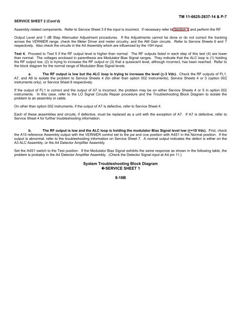
SERVICE SHEET 2 (Cont’d)<br />
<strong>TM</strong> <strong>11</strong>-<strong>6625</strong>-<strong>2837</strong>-14 & P-7<br />
Assembly related components. Refer to Service Sheet 3 if the input is incorrect. If necessary refer to Section V and perform the RF<br />
Output Level and 1 dB Step Attenuator Adjustment procedures. If the Adjustments cannot be done or do not correct the tracking<br />
across the VERNIER range, check the Meter Driver and meter circuitry, and the AM Gain circuits. Refer to Service Sheets 6 and 7<br />
respectively. Also check the circuits in the A4 Assembly which are influenced by the 10H input.<br />
Test 4. Proceed to Test 5 if the RF output level is higher than normal. The RF outputs listed in each step of this test (4) are lower<br />
than normal. The voltages enclosed in parenthesis are Modulator Bias Signal ranges. They indicate that the ALC loop is (1) holding<br />
the RF output low, (2) is trying to increase the RF output or (3) that a quiescent level, although incorrect, has been reached. Refer to<br />
the block diagram for the normal range of Modulator Bias Signal levels.<br />
a. The RF output is low but the ALC loop is trying to increase the level (>-3 Vdc). Check the RF outputs of FL1,<br />
A7, and A6 to isolate the problem to Service Sheets 4 (for other than option 002 instruments), Service Sheets 4 or 5 (option 002<br />
instruments only), or Service Sheet 6 respectively.<br />
If the output of FL1 is correct and the output of A7 is incorrect, the problem may be on either Service Sheets 4 or 5 in option 002<br />
instruments. In this case, refer to the LO Signal Circuits Repair procedure and the Troubleshooting Block Diagram to isolate the<br />
problem to an assembly or cable.<br />
On other than option 002 instruments, if the output of A7 is defective, refer to Service Sheet 4.<br />
Each of these assemblies and circuits, if defective, must be replaced as a unit with the exception of A7. If A7 is defective, refer to<br />
Service Sheet 4 for further troubleshooting information.<br />
b. The RF output is low and the ALC loop is holding the modulator Bias Signal level low (>+10 Vdc). First, check<br />
the A10 reference Assembly output with the VERNIER control set to the pw and ccw position with A4S1 in the Normal position. If the<br />
output is abnormal, refer to the troubleshooting information on Service Sheet 7. A normal output indicates the defect is either on the<br />
A3 ALC Assembly, or the A4 Detector Amplifier Assembly.<br />
Set the A4S1 switch to the Test position. If the Modulator Bias Signal exhibits the same response as shown in the following table, the<br />
problem is probably in the A4 Detector Amplifier Assembly. (Check the Detector Signal input at A4 pin <strong>11</strong>.)<br />
System Troubleshooting Block Diagram<br />
SERVICE SHEET 1<br />
8-18B
![[6]](https://img.yumpu.com/23901941/1/184x260/6.jpg?quality=85)