TM 11-6625-2837-14&P-7 TECHNICAL MANUAL OPERATOR'S ...
TM 11-6625-2837-14&P-7 TECHNICAL MANUAL OPERATOR'S ...
TM 11-6625-2837-14&P-7 TECHNICAL MANUAL OPERATOR'S ...
You also want an ePaper? Increase the reach of your titles
YUMPU automatically turns print PDFs into web optimized ePapers that Google loves.
Section 3 <strong>TM</strong> <strong>11</strong>-<strong>6625</strong>-<strong>2837</strong>-14&P-7<br />
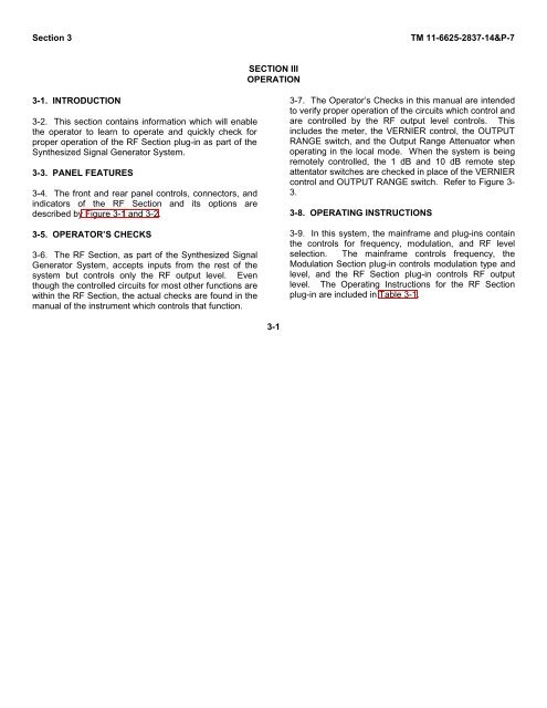
3-1. INTRODUCTION<br />
3-2. This section contains information which will enable<br />
the operator to learn to operate and quickly check for<br />
proper operation of the RF Section plug-in as part of the<br />
Synthesized Signal Generator System.<br />
3-3. PANEL FEATURES<br />
3-4. The front and rear panel controls, connectors, and<br />
indicators of the RF Section and its options are<br />
described by Figure 3-1 and 3-2.<br />
3-5. OPERATOR’S CHECKS<br />
3-6. The RF Section, as part of the Synthesized Signal<br />
Generator System, accepts inputs from the rest of the<br />
system but controls only the RF output level. Even<br />
though the controlled circuits for most other functions are<br />
within the RF Section, the actual checks are found in the<br />
manual of the instrument which controls that function.<br />
SECTION III<br />
OPERATION<br />
3-1<br />
3-7. The Operator’s Checks in this manual are intended<br />
to verify proper operation of the circuits which control and<br />
are controlled by the RF output level controls. This<br />
includes the meter, the VERNIER control, the OUTPUT<br />
RANGE switch, and the Output Range Attenuator when<br />
operating in the local mode. When the system is being<br />
remotely controlled, the 1 dB and 10 dB remote step<br />
attentator switches are checked in place of the VERNIER<br />
control and OUTPUT RANGE switch. Refer to Figure 3-<br />
3.<br />
3-8. OPERATING INSTRUCTIONS<br />
3-9. In this system, the mainframe and plug-ins contain<br />
the controls for frequency, modulation, and RF level<br />
selection. The mainframe controls frequency, the<br />
Modulation Section plug-in controls modulation type and<br />
level, and the RF Section plug-in controls RF output<br />
level. The Operating Instructions for the RF Section<br />
plug-in are included in Table 3-1.


![[6]](https://img.yumpu.com/23901941/1/184x260/6.jpg?quality=85)
