TM 11-6625-2837-14&P-7 TECHNICAL MANUAL OPERATOR'S ...
TM 11-6625-2837-14&P-7 TECHNICAL MANUAL OPERATOR'S ...
TM 11-6625-2837-14&P-7 TECHNICAL MANUAL OPERATOR'S ...

You also want an ePaper? Increase the reach of your titles
YUMPU automatically turns print PDFs into web optimized ePapers that Google loves.
Section 4 <strong>TM</strong> <strong>11</strong>-<strong>6625</strong>-<strong>2837</strong>-14&P-7<br />
4-9. FREQUENCY RANGE<br />
PERFORMANCE TESTS<br />
SPECIFICATION:<br />
1 to 1299.999999 MHz selectable in 1 Hz steps. Frequencies from 200 to kHz to 1 MHz may also be selected with some<br />
degradation in specifications.<br />
DESCRIPTION:<br />
The Synthesized Signal Generator System RF OUTPUT is monitored by a frequency counter which supplies a common<br />
time base reference signal. The frequencies are checked at the extremes. Any specified frequency may be checked.<br />
EQUIPMENT:<br />
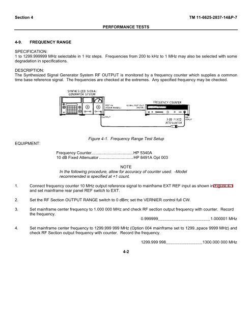
Figure 4-1. Frequency Range Test Setup<br />
Frequency Counter... .................................HP 5340A<br />
10 dB Fixed Attenuator ..............................HP 8491A Opt 003<br />
NOTE<br />
In the following procedure, allow for accuracy of counter used. -Model<br />
recommended is specified at +1 count.<br />
1. Connect frequency counter 10 MHz output reference signal to mainframe EXT REF input as shown in Figure 4-1<br />
and set mainframe rear panel REF switch to EXT.<br />
2. Set the RF Section OUTPUT RANGE switch to 0 dBm; set the VERNIER control full CW.<br />
3. Set mainframe center frequency to 1.000 000 MHz and check RF section output frequency with counter. Record<br />
the frequency.<br />
0.999999_______________________1.000001 MHz<br />
4. Set mainframe center frequency to 1299.999 999 MHz (Option 004 mainframe set to 1299.,space 9999 MHz) and<br />
check RF Section output frequency with counter. Record the frequency.<br />
4-2<br />
1299.999 998________________1300.000 000 MHz
![[6]](https://img.yumpu.com/23901941/1/184x260/6.jpg?quality=85)