TM 11-6625-2837-14&P-7 TECHNICAL MANUAL OPERATOR'S ...
TM 11-6625-2837-14&P-7 TECHNICAL MANUAL OPERATOR'S ...
TM 11-6625-2837-14&P-7 TECHNICAL MANUAL OPERATOR'S ...

Create successful ePaper yourself
Turn your PDF publications into a flip-book with our unique Google optimized e-Paper software.
Section 4 <strong>TM</strong> <strong>11</strong>-<strong>6625</strong>-<strong>2837</strong>-14&P-7<br />
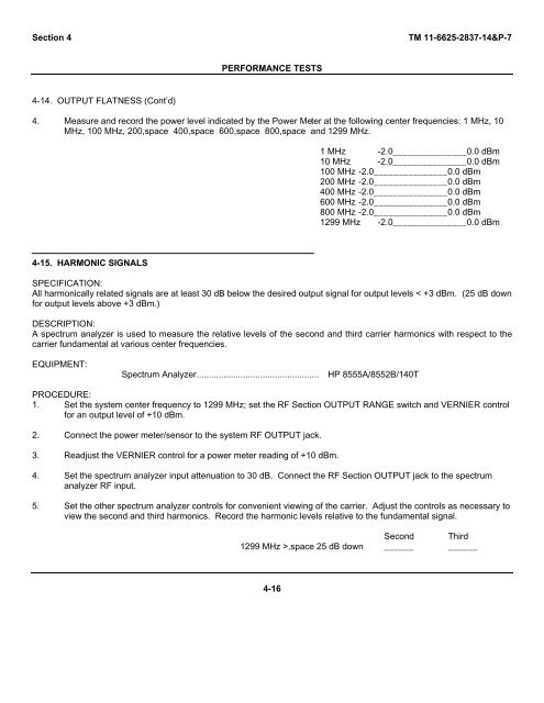
4-14. OUTPUT FLATNESS (Cont’d)<br />
PERFORMANCE TESTS<br />
4. Measure and record the power level indicated by the Power Meter at the following center frequencies: 1 MHz, 10<br />
MHz, 100 MHz, 200,space 400,space 600,space 800,space and 1299 MHz.<br />
4-15. HARMONIC SIGNALS<br />
1 MHz -2.0_______________0.0 dBm<br />
10 MHz -2.0_______________0.0 dBm<br />
100 MHz -2.0_______________0.0 dBm<br />
200 MHz -2.0_______________0.0 dBm<br />
400 MHz -2.0_______________0.0 dBm<br />
600 MHz -2.0_______________0.0 dBm<br />
800 MHz -2.0_______________0.0 dBm<br />
1299 MHz -2.0_______________0.0 dBm<br />
SPECIFICATION:<br />
All harmonically related signals are at least 30 dB below the desired output signal for output levels < +3 dBm. (25 dB down<br />
for output levels above +3 dBm.)<br />
DESCRIPTION:<br />
A spectrum analyzer is used to measure the relative levels of the second and third carrier harmonics with respect to the<br />
carrier fundamental at various center frequencies.<br />
EQUIPMENT:<br />
Spectrum Analyzer.................................................. HP 8555A/8552B/140T<br />
PROCEDURE:<br />
1. Set the system center frequency to 1299 MHz; set the RF Section OUTPUT RANGE switch and VERNIER control<br />
for an output level of +10 dBm.<br />
2. Connect the power meter/sensor to the system RF OUTPUT jack.<br />
3. Readjust the VERNIER control for a power meter reading of +10 dBm.<br />
4. Set the spectrum analyzer input attenuation to 30 dB. Connect the RF Section OUTPUT jack to the spectrum<br />
analyzer RF input.<br />
5. Set the other spectrum analyzer controls for convenient viewing of the carrier. Adjust the controls as necessary to<br />
view the second and third harmonics. Record the harmonic levels relative to the fundamental signal.<br />
Second Third<br />
1299 MHz >,space 25 dB down ______ ______<br />
4-16
![[6]](https://img.yumpu.com/23901941/1/184x260/6.jpg?quality=85)