TM 11-6625-2837-14&P-7 TECHNICAL MANUAL OPERATOR'S ...
TM 11-6625-2837-14&P-7 TECHNICAL MANUAL OPERATOR'S ...
TM 11-6625-2837-14&P-7 TECHNICAL MANUAL OPERATOR'S ...

Create successful ePaper yourself
Turn your PDF publications into a flip-book with our unique Google optimized e-Paper software.
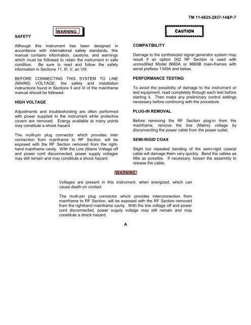
SAFETY<br />
WARNING<br />
Although this instrument has been designed in<br />
accordance with international safety standards, this<br />
manual contains information, cautions, and warnings<br />
which must be followed to retain the instrument in safe<br />
condition. Be sure to read and follow the safety<br />
information in Sections <strong>11</strong>, III, V, an VIII.<br />
BEFORE CONNECTING THIS SYSTEM TO LINE<br />
(MAINS) VOLTAGE, the safety and installation<br />
instructions found in Sections II and III of the mainframe<br />
manual should be followed.<br />
HIGH VOLTAGE<br />
Adjustments and troubleshooting are often performed<br />
with power supplied to the instrument while protective<br />
covers are removed. Energy available at many points<br />
may constitute a shock hazard<br />
The multi-pin plug connector which provides inter<br />
connection from mainframe to RF Section, will be<br />
exposed with the RF Section removed from the righthand<br />
mainframe cavity. With the Line (Mains Voltage off<br />
and power cord disconnected, power supply voltages<br />
may still remain and may constitute a shock hazard.<br />
WARNING<br />
COMPATIBILITY<br />
<strong>TM</strong> <strong>11</strong>-<strong>6625</strong>-<strong>2837</strong>-14&P-7<br />
Damage to the synthesized signal generator system may<br />
result if an option 002 RF Section is used with<br />
unmodified Model 8660A or 8660B main-frames with<br />
serial prefixes 1349A and below.<br />
PERFORMANCE TESTING<br />
To avoid the possibility of damage to the instrument or<br />
test equipment, read completely through each test before<br />
starting it. Then make any preliminary control settings<br />
necessary before continuing with the procedure.<br />
PLUG-IN REMOVAL<br />
Before removing the RF Section plug-in from the<br />
mainframe, remove the line (Mains) voltage by<br />
disconnecting the power cable from the power outlet.<br />
SEMI-RIGID COAX<br />
Slight but repeated bending of the semi-rigid coaxial<br />
cable will damage them very quickly. Bend the cables as<br />
little as possible. If necessary, loosen the assembly to<br />
release the cable.<br />
Voltages are present in this instrument, when energized, which can<br />
cause death on contact.<br />
The multi-pin plug connector which provides interconnection from<br />
mainframe to RF Section, will be exposed with the RF Section removed<br />
from the righthand mainframe cavity. With the line voltage off and power<br />
cord disconnected, power supply voltage may still remain and may<br />
constitute a shock hazard.<br />
A
![[6]](https://img.yumpu.com/23901941/1/184x260/6.jpg?quality=85)