TC-L42U5X
TC-L42U5X
TC-L42U5X
Create successful ePaper yourself
Turn your PDF publications into a flip-book with our unique Google optimized e-Paper software.
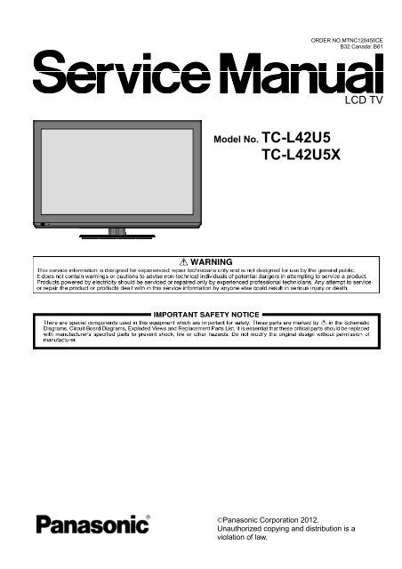
Model No. <strong>TC</strong>-L42U5<br />
<strong>TC</strong>-<strong>L42U5X</strong><br />
ORDER NO.MTNC120450CE<br />
B32 Canada: B61<br />
©Panasonic Corporation 2012.<br />
Unauthorized copying and distribution is a<br />
violation of law.<br />
LCD TV
CONTENTS<br />
1. Safety precautions .................................................................................................3<br />
2. Alignment instructions and method of software upgrading.....................................5<br />
3. Working principle analysis of the unit ................................................................... 14<br />
4. Block diagram ......................................................................................................15<br />
5. IC block diagram..................................................................................................16<br />
6. Wiring diagram ...................................................................................................28<br />
7. Troubleshooting guide..........................................................................................32<br />
8. Exploded View .....................................................................................................36<br />
9. Replacement Parts List........................................................................................38<br />
10. Boards Layout....................................................................................................39<br />
2
Attention: This service manual is only for service personnel to take reference with. Before servicing<br />
please read the following points carefully.<br />
Safety precautions<br />
1. Instructions<br />
Be sure to switch off the power supply before replacing or welding any components or<br />
inserting/plugging in connection wire Anti static measures to be taken (throughout the entire production<br />
process!):<br />
a) Do not touch here and there by hand at will;<br />
b) Be sure to use anti static electric iron;<br />
c) It’s a must for the welder to wear anti static gloves.<br />
Please refer to the detailed list before replacing components that have special safety requirements.<br />
Do not change the specs and type at will.<br />
2. Points for attention in servicing of LCD<br />
2.1 Screens are different from one model to another and therefore not interchangeable. Be sure to<br />
Use the screen of the original model for replacement.<br />
2.2 The operation voltage of LCD screen is high voltage. Be sure to take proper measures in<br />
protecting yourself and the machine when testing the system in the course of normal operation or<br />
right after the power is switched off. Please do not touch the circuit or the metal part of the module<br />
That is in operation mode. Relevant operation is possible only one minute after the power is switched<br />
off.<br />
2.3 Do not use any adapter that is not identical with the TV set. Otherwise it will cause fire or damage<br />
to the set.<br />
2.4 Never operate the set or do any installation work in bad environment such as wet bathroom,<br />
laundry, kitchen, or nearby fire source, heating equipment and devices or exposure to sunlight etc.<br />
Otherwise bad effect will result.<br />
2.5 If any foreign substance such as water, liquid, metal slices or other matters happens to fall into the<br />
module, be sure to cut the power off immediately and do not move anything on the module lest it should<br />
cause fire or electric shock due to contact with the high voltage or short circuit.<br />
2.6 Should there be smoke, abnormal smell or sound from the module, please shut the power off at<br />
once. Likewise, if the screen is not working after the power is on or in the course of operation, the<br />
power must be cut off immediately and no more operation is allowed under the same condition.<br />
2.7 Do not pull out or plug in the connection wire when the module is in operation or just after the<br />
power is off because in this case relatively high voltage still remains in the capacitor of the driving<br />
circuit. Please wait at least one minute before the pulling out or plugging in the connection wire.<br />
2.8 When operating or installing LCD please don’t subject the LCD components to bending, twisting or<br />
extrusion, collision lest mishap should result.<br />
2.9 As most of the circuitry in LCD TV set is composed of CMOS integrated circuits, it’s necessary to<br />
pay attention to anti statics. Before servicing LCD TV make sure to take anti static measure and<br />
ensure full grounding for all the parts that have to be grounded.<br />
2.10 There are lots of connection wires between parts behind the LCD screen. When servicing or<br />
moving the set please take care not to touch or scratch them. Once they are damaged the screen<br />
would be unable to work and no way to get it repaired.<br />
If the connection wires, connections or components fixed by the thermo tropic glue need to disengage<br />
when service, please soak the thermo tropic glue into the alcohol and then pull them out in case of<br />
damage.<br />
3
2.11 Special care must be taken in transporting or handling it. Exquisite shock vibration may lead to<br />
breakage of screen glass or damage to driving circuit. Therefore it must be packed in a strong case<br />
before the transportation or handling.<br />
2.12 For the storage make sure to put it in a place where the environment can be controlled so as to<br />
prevent the temperature and humidity from exceeding the limits as specified in the manual. For<br />
prolonged storage, it is necessary to house it in an anti-moisture bag and put them altogether in one<br />
place. The ambient conditions are tabulated as follows:<br />
Temperature Scope for operation 0 ~ + 40 o C<br />
Scope for storage -20 ~ + 60 o C<br />
Humidity Scope for operation 20% ~ 90 %<br />
Scope for storage 5% ~ 90%<br />
2.13 Display of a fixed picture for a long time may result in appearance of picture residue on the<br />
screen, as commonly called “ghost shadow”. The extent of the residual picture varies with the maker<br />
of LCD screen. This phenomenon doesn’t represent failure. This “ghost shadow” may remain<br />
in the picture for a period of time (several minutes). But when operating it please avoid displaying still<br />
picture in high brightness for a long time.<br />
3. Points for attention during installation<br />
3.1 The front panel of LCD screen is of glass. When installing it please make sure to put it in place.<br />
3.2 For service or installation it’s necessary to use specified screw lest it should damage the screen.<br />
3.3 Be sure to take anti dust measures. Any foreign substance that happens to fall down between the<br />
screen and the glass will affect the receiving and viewing effect<br />
3.4 When dismantling or mounting the protective partition plate that is used for anti vibration and<br />
insulation please take care to keep it in intactness so as to avoid hidden trouble.<br />
3.5 Be sure to protect the cabinet from damage or scratch during service, dismantling or mounting.<br />
4
2. Alignment instructions<br />
(1) Test equipment<br />
VG-859 (YPbPr, VGA, HDMI signal generator)<br />
FLUKE 54200(TV signal generator)<br />
CA210 (white balancer)<br />
(2) Power test<br />
Connect main board, power board and IR board according the wiring diagram, connect<br />
the power and press power key (Remote controller or Keypad) button to turn on the TV.<br />
a) Test the pin voltage of P802/power board , the data is shown in table1:<br />
Table1 voltage data of P802<br />
For 42”<br />
P802 Pin1,2 Pin3,4 Pin5,6,7 Pin8,9 Pin10,11<br />
Voltage GND 11.4V~12.6V GND 11.4V~12.6V 4.75V~5.25V<br />
For 42”<br />
Pin12 Pin13 Pin 14 Pin15 Pin16<br />
On:2.5V-5.25V<br />
Off: 0-0.5V<br />
Normal:0V~0.5V<br />
Abnormal :Open drain<br />
On:2.5V-5.25V<br />
Off: 0-0.5V<br />
5<br />
Duty 20%~100% NC
(3) Alignment flow-chart<br />
The alignment flow-chart is shown as fig-1<br />
Check if DDC, HDCP KEY, FLASH are written<br />
Combined test for general assembly<br />
White balance adjustment<br />
Connect to the center signal source and check each<br />
Function of TV (station leaking, analog control, etc.)<br />
Check the output of earphone and speaker.<br />
Input AV signal and check the function<br />
Input HD signal and check the function of YPbPr<br />
Input VGA signal and check if the display is normal, check<br />
the function (analog control), horizontal/vertical center, etc.<br />
Input USB signal and check if the display is normal, check<br />
the function (analog control), horizontal/vertical center, etc.<br />
Input HDMI signal and check if the display is normal, check<br />
the function (analog control), horizontal/vertical center, etc.<br />
Preset ex-factory<br />
Check the accessories and packing<br />
Fig-1 adjustment flow-chart<br />
6
(4) Adjustment instruction<br />
At any input source then press the “←”, “EXIT” and “OK” (Remote control within 1 sec) to enter factory mode<br />
During Factory menu, if “MENU” key is pushed, system will exit factory mode.<br />
4-1. Source Calibration<br />
4-1.1. Set the signal generator to input sources Component on LCD-TV; ASTRO-859 signal setting to NTSC-M<br />
(PG2 mode Timing 924 and Pattern 984 SMPTE Color Bar.)<br />
4-1.2. Entering into factory Mode: Press up or down key of remote control to select “Source Calibration”, Press<br />
「OK」 key to enter the item.<br />
-> Source calibration performed automatically when finished that will show OK.<br />
Repeat step 2 to do VGA input sources,<br />
ASTRO-859 signal setting to1024X768 60Hz. (PG2 mode: Timing 963 and Pattern 942 16step H-grayscale +<br />
white border.)<br />
7
4-2. Color Temperature Adjustment & Check<br />
4-2.1. Set the signal generator to RGB, 1024*768, 60HZ(ASTRO-859: PG1 856), Level: 77(30%) or<br />
178(70%). Full white pattern. (RGB gain and offset all should not over 128,and one of RGB gain and offset<br />
have to be setting on 110. )<br />
4-2.2. Press up or down key of remote control to select “Cool”, Press 「ENTER」 key to enter the item.<br />
RGAIN, GGAIN, BGAIN, ROFFSET, GOFFSET, BOFFSET, drive values are set for Warm, Normal,<br />
and Cool independently.<br />
4-2.3. Select 「Warm」<br />
Step 1.First Turning Gain parts of RGB.<br />
(1) Warm spec.:<br />
x= 0.316±0.005<br />
y= 0.338±0.005<br />
(2) If the x and y value are larger than specification,<br />
Decrease R GAIN drive from default value.<br />
Increase B GAIN drive from default value.<br />
(3) If the x or y or both x and y value is/are smaller than specification.<br />
Decrease B GAIN drive from default value<br />
(4) According to a x and y value, please following adjustment of (4)-1 or (4)-2.<br />
(4)-1 If x value is higher than spec<br />
Decrease R GAIN drive from default value.<br />
Increase B GAIN drive from default value.<br />
(4)-2 If y value is higher than spec,<br />
Decrease B GAIN drive from default value<br />
Step 2.When finish Gain parts, then turning OFFSET parts<br />
Select 「Normal」<br />
(1) Medium spec.: (Same as the Gain session )<br />
x= 0.288±0.005<br />
y= 0.310±0.005<br />
(2) If the x and y value are larger than specification,<br />
Decrease R OFFSET drive from default value.<br />
Increase B OFFSET drive from default value.<br />
(3) If the x or y or both x and y value is/are smaller than specification.<br />
Decrease B OFFSET drive from default value<br />
(4) According to a x and y value, please following adjustment of (4)-1 or (4)-2.<br />
(4)-1 If x value is higher than spec<br />
Decrease R OFFSET drive from default value.<br />
Increase B OFFSET drive from default value.<br />
(4)-2 If y value is higher than spec,<br />
Decrease B OFFSET drive from default value<br />
Step 3.When finishing OFFSET parts, then recheck Gain parts .unitl Both of them meet the<br />
target specification<br />
Step 3. Than select 「Cool」 using same way to adjust the setting.<br />
4-2.4. Exit Factory Mode:<br />
After finish adjusting color temperature press [MENU] to exit factory mode.<br />
8
(5) Items of Factory menu<br />
When in PC/ Component/ Video (Composite)/ ANT inputs then press the “Left -> Exit -> Enter” key of remote<br />
control to enter factory mode..<br />
During Factory menu, if “MENU” or “EXIT” key is pushed, system will exit factory mode.<br />
Press up and down key can move high light item from Color Temperature -> Timer Clear -> Preset Channel-<br />
>NVRAM Clear-> Full Power -> Source Calibration -> Reset to Default -> RF Burn In -> USB F/W Upgrade -><br />
UART Enable-> Bypass Gamma.<br />
The Timer Clear, NVRAM Clear and Reset to Default items will have a check dialog “yes or no” to do or not.<br />
Push “Enter” key can select high light item function. (Press left and right can adjust value)<br />
Display panel Burn in Time on the bottom.<br />
Display model name, firmware version and released date on top.<br />
1) Factory Color Temp data edit<br />
Press up or down key can select high light item function<br />
Press enter key to enter the item.<br />
-Color temp default preset No (Warm, Medium, Cool).<br />
-R, G, B data for each preset<br />
Press “Up” or “Down” key to select “R”, “G”, “B” item<br />
Press “Left” or “Right” key to set the “R”, “G”, “B” value<br />
Press “MENU” or “EXIT” item to exit to factory mode<br />
2) Timer Clear<br />
Reset the timer which records hours of LCD panel burn in<br />
This item will have a check dialog “yes or no” to do or not.<br />
- Time in factory mode: Time function shall be displayed automatically. Saving the total time of system<br />
power on (LCD turn on), and count the time automatically. The timer is continuous and saved (per 10<br />
minutes) forever, unless it will be reset by doing “Timer Clear”.<br />
3) Preset channel<br />
Load preset channel for production line. (Refer 4.4.4 Preset channel table).<br />
4) NVRAM CLEAR<br />
Initialize program’s default values to NVRAM for following adjustment items accuracy.<br />
In factory mode it is the first and important step to make sure all values are default value and correct<br />
- Reset settings: Gamma table, Channel table (Favorite channel, Channel label etc.), Model table<br />
(H/V Position, Clock, Phase), Source dependent setting (Contrast, Brightness etc.), Common setting<br />
(Volume, Language etc.), Parental Control (Rating, Password etc), Closed Caption.<br />
To avoid a mistake initial process after factory setting is done. This item will have a check dialog “yes<br />
or no” to do the initial or not.<br />
Notice:<br />
9
After this item is processed then the DUT needs to be powered off then AC powered off.<br />
5) Full power<br />
This is for power consumption testing.<br />
To measure the maximum power consumption of TV set, we adjust the value of following items to<br />
maximum.<br />
- Video: Contrast maximum value, Brightness maximum value, Backlight maximum value.<br />
- Audio: Volume maximum value, Bass default value, Treble default value.<br />
Press enter key to turn on Full Power and OSD stay display until press enter key to recover from Full<br />
Power<br />
6) Source Calibration<br />
Source Calibration (gain/offset) must be adjusted color by firmware automatic adjustment in PC,<br />
Composite and Component input source.<br />
This item will have a result dialog “OK” or “NG”.<br />
7) Reset to Default<br />
Reset all settings of OSD menu to default value.<br />
- Reset settings: Channel table, Model table (H/V Position, Clock, Phase), Source dependent setting<br />
(Contrast, Brightness etc.), Common setting (Volume, Language etc.), Parental Control (Rating,<br />
Password etc), Closed Caption.<br />
8) RF Burn In<br />
Use “snow” pattern for burn in. Selected items are “On” and “Off”.<br />
While turn on burn in mode, firmware will automatically turn off “Auto power off” function.<br />
If there is no power supply suddenly, firmware will re-enter burn in mode automatically when power<br />
supply is back<br />
Pressed the “Power” key, firmware will automatically turn off burn in mode.<br />
Burn in mode: Source is “ANT/Cable" and channel is NTSC channel 3.<br />
9) USB F/W Upgrade<br />
Upgrade firmware through USB.<br />
10) UART Enable<br />
Enable to communicate with Auto-Alignment system.<br />
11) Bypass Gamma<br />
For factory test value of gamma.<br />
(6) Performance check<br />
6-1 TV function<br />
Connect RF to the center signal source, enter Channel menu → auto tuning, check if there are channels be<br />
skipped, check if the picture and speaker are normal.<br />
6-2 AV terminals<br />
Input Video signal, check if the picture and sound are normal.<br />
6-3 YPbPr terminal<br />
Input YUV signal (VG859 signal generator), separately input the YUV signals listed in table4 and check if the<br />
display and sound are normal at any situation (power on, channel switch and format convert, etc.)<br />
MODE<br />
FREQ PERIOD<br />
LINE(kHz)<br />
FRAME<br />
(Hz)<br />
LINE (pixel)<br />
FIELD<br />
(lines)<br />
Table4 YUV signal format<br />
SYNC<br />
POLARITY<br />
LINE<br />
FIELD<br />
10<br />
PIXEL<br />
CLOCK<br />
(MHz)<br />
Display<br />
LINE (pixel)<br />
FRAME<br />
(lines)<br />
SYNC<br />
WIDTH<br />
LINE (pixel)<br />
FRAME<br />
(lines)<br />
BACK<br />
PORCH<br />
LINE (pixel)<br />
FRAME<br />
(lines)<br />
15.734 1716 Negitive 27 1440 124 114<br />
59.94Hz 720x480i 59.94 525 Negitive 480 3 15<br />
31,469 858 Negitive 27 720 62 60<br />
59.94Hz 720x480P 59.94 525 Negitive 480 6 30
45 1650 Positive 74.25 1280 40 220<br />
60Hz 1280x720P 60 750 Positive 720 5 20<br />
33.75 2200 Positive 74.25 1920 44 148<br />
60Hz 1920X1080i 60 1125 Positive 1080 5 15<br />
67.5 2200 Positive 148.5 1920 44 148<br />
60Hz 1920X1080P 60 1125 Positive 1080 5 36<br />
6-4 VGA terminal<br />
Input VGA signal (VG848 signal generator), separately input the signals listed in table5 and check the display and<br />
sound. If the image is deflection of the Horizontal and vertical, select Menu->Setup->Auto Adjust to perform autocorrect.<br />
Table5 VGA signal format<br />
Mode<br />
FREQ PERIOD<br />
LINE(kHz)<br />
FRAME(Hz)<br />
LINE (pixel)<br />
FIELD(lines)<br />
SYNC<br />
POLARITY<br />
LINE<br />
FIELD<br />
11<br />
PIXEL<br />
CLOCK<br />
(MHz)<br />
Display<br />
LINE (pixel)<br />
FRAME(lines)<br />
SYNC<br />
WIDTH<br />
LINE (pixel)<br />
FRAME<br />
(lines)<br />
BACK<br />
PORCH<br />
LINE (pixel)<br />
FRAME<br />
(lines)<br />
VGA 60Hz 31.469 800 Negative 25.175 640 96 40<br />
640x480 59.941 525 Negative 480 2 25<br />
SVGA 60Hz 37.879 1056 Positive 40 800 128 88<br />
800x600 60.317 628 Positive 600 4 23<br />
XGA 60Hz 48.363 1344 Negative 65 1024 136 160<br />
1024x768 60.004 806 Negative 768 6 29<br />
WXGA 60Hz 47.776 1664 Negative 79.5 1280 128 192<br />
1280x768 59.87 798 Positive 768 7 20<br />
WXGA 60Hz 47.712 1792 Positive 85.5 1360 112 256<br />
1360x768 60.015 795 Positive 768 6 18<br />
SXGA 60Hz 63.981 1688 Positive 108 1280 112 248<br />
1280x1024 60.02 1066 Positive 1024 3 38<br />
6-5 HDMI terminal<br />
Input HDMI signal (VG859 signal generator), separately input the signals listed in table6 and check the display and<br />
sound (32 KHz, 44.1 KHz, 48 KHz) at any situation (power on, channel switch and format convert, etc.)<br />
FREQ FREQ PERIOD<br />
MODE<br />
LINE(kHz)<br />
FRAME(Hz)<br />
LINE (pixel)<br />
FIELD(lines)<br />
Table6 HDMI signal format<br />
SYNC<br />
POLARITY<br />
LINE<br />
FIELD<br />
PIXEL<br />
CLOCK<br />
(MHz)<br />
Display<br />
LINE (pixel)<br />
FRAME<br />
(lines)<br />
SYNC<br />
WIDTH<br />
LINE (pixel)<br />
FRAME<br />
(lines)<br />
BACK<br />
PORCH<br />
LINE (pixel)<br />
FRAME<br />
(lines)<br />
VGA 60Hz 31.469 800 Negitive 25.175 640 96 40<br />
640x480 59.94 525 Negitive 480 2 25<br />
SVGA 60Hz 37.879 1056 Positive 40 800 128 88
800x600 60.317 628 Positive 600 4 23<br />
XGA 60Hz 48.363 1344 Negitive 65 1024 136 160<br />
1024x768 60.004 806 Negitive 768 6 29<br />
SXGA 60Hz 63.981 1688 Positive 108 1280 112 248<br />
1280x1024 60.02 1066 Positive 1024 3 38<br />
WXGA 60Hz 47.776 1664 Negitive 79.5 1280 128 192<br />
1280x768 59.87 798 Positive 768 7 20<br />
WXGA 60Hz 47.712 1792 Positive 85.5 1360 112 256<br />
1360x768 60.015 795 Positive 768 6 18<br />
59.94Hz 720x480i 15.734 1716 Negitive 27 1440 124 114<br />
59.94 525 Negitive 480 3 15<br />
59.94Hz 720x480P 31.469 858 Negitive 27 720 62 60<br />
59.94 525 Negitive 480 6 30<br />
60Hz 1280x720P 45 1650 Positive 74.25 1280 40 220<br />
60 750 Positive 720 5 20<br />
60Hz 1920X1080i 33.75 2200 Positive 74.25 1920 44 148<br />
60 1125 Positive 1080 5 15<br />
60Hz 1920X1080P 67.5 2200 Positive 148.5 1920 44 148<br />
60 1125 Positive 1080 5 36<br />
24Hz 1920x1080P 27 2750 Positive 74.25 1920 44 148<br />
24 1125 Positive 1080 5 36<br />
6-6 other functions check<br />
a) Check the turn on/turn off timer, sleep timer, picture/sound mode, OSD, stereo and analog TV Teletext, etc.<br />
(7) Firmware update process<br />
(1) Plug the USB with the firmware file named SPB42TT.ecc<br />
(2) If system detect SPB42TT.ecc, USB upgrade message would appear automatically.<br />
(3) Press Left key to select Yes, and then press OK key to start the upgrading.<br />
12
(4) Upgrading is starting, please wait for the progress finish.<br />
(5) When the progress completed, please follow the instruction to remove USB and restart by AC off<br />
then on.<br />
13
Working principle analysis of the unit<br />
1. NTSC signals flow:<br />
Antenna signal will be send to tuner ENV56U05D8F, then Tuner will be demodulating and<br />
output standard video signal TV-CVBS, and sound SIF signal.<br />
TV-CVBS will send to the master control IC ZR39748 to video decode, de-interlace and scaler, then<br />
output LVDS level drive for panel display.<br />
The sound IF (SIF) will be fed into ZR39748, after demodulating, pre-amplifying, bass adjusting and<br />
volume control, the sound signal will be transform into digital I2S signal and sent to<br />
digital amplifier BD5452AMUV.<br />
2. Composite/Component signal flow<br />
Composite signal and Component signal will be fed to ZR39748 to perform video decode, deinterlace<br />
and scaler, then output LVDS drive level for panel display.<br />
Audio signal from Composite/Component terminal via matched resistance is fed to ZR39748 to bass<br />
adjust and volume control, the sound signal will be transform into digital I2S signal and sent<br />
to digital amplifier BD5452AMUV.<br />
3. PC signal flow<br />
PC signal via terminal socket sent to ZR39748 A/D, PC output R/G/B of 24 bit to back end<br />
module to Video decode, de-interlace and image scale, then send to LVDS level drive for panel<br />
display.<br />
Sound signal of PC terminal via matched resistance and sent to ZR39748 to bass adjust and<br />
volume control, the sound signal will be transform into digital I2S signal and sent to digital<br />
amplifier BD5452AMUV.<br />
4. HDMI signal flow<br />
Two HDMI video signals are directly fed to the master control IC ZR39748 to digital decode, image<br />
scale, then output LVDS drive level for panel display. HDMI audio signal via decoder built-in ZR39748<br />
to bass adjust and volume control, the sound signal will be transform into digital I2S signal<br />
and sent to digital amplifier BD5452AMUV.<br />
5. USB signal flow<br />
USB signal via USB connector sent to ZR39748 and its A/D conversion to YPbPr output for<br />
ZR39748, then output R/G/B of 24 bit to back end module to Video decode, de-interlace and<br />
image scale, then send to LVDS level drive for panel display.<br />
Sound signal of USB signal via matched resistance and sent to ZR39748 to bass adjust and<br />
volume control, the sound signal will be transform into digital I2S signal and sent to digital<br />
amplifier BD5452AMUV.<br />
14
4-1 Block Diagram<br />
SPB42T 42” Block Diagram<br />
15
IC block diagram<br />
1. Zoran ZR748<br />
• Integrated Digital & Analog Demodulator<br />
• 8VSB/QAM-B<br />
• NTSC/BTSC/A2K<br />
• Video Inputs<br />
• Three (3) 1080p HDMI (v1.4a/DC)*<br />
• One (1) 1080p YPbPr<br />
• One (1) VGA, up to WUXGA resolution<br />
• Two (2) CVBS*, One (1) S-Video<br />
• Audio Inputs<br />
• Five (5) stereo L/R line-level*<br />
• Internal Video/Audio Processing<br />
• NTSC video decoder<br />
• MPEG-2 decoder<br />
• 10-bit video processing<br />
• 1080i motion-adaptive de-interlacer<br />
• ACM-2D color processor<br />
• Graphics blending/overlay<br />
• Audio DSP<br />
• Video Outputs<br />
• Dual-channel LVDS (1080p, up to 10bpp)<br />
• miniLVDS & RSDS (6/8bpp, up to 330MHz)<br />
• LCD panel timing control signals (<strong>TC</strong>ON)<br />
• Audio Outputs<br />
• One (1) stereo L/R DDX differential<br />
• One (1) stereo L/R single-ended DDX<br />
• Optional up-to-four (4) more single-ended DDX<br />
• Optional up-to-three (3) I2S stereo pairs<br />
• One (1) S/PDIF<br />
• System Processors & Interfaces<br />
• 300MHz system CPU<br />
• TV microcontroller for standby mode<br />
• One (1) USB 2.0<br />
• External SPI Flash Memory: 2-16MByte<br />
• 2-4MB typical for ATSC DTV application<br />
• External 16-bit DDR2 Required<br />
• DDR2-800 for most design configurations<br />
• DDR2-1066 for 1080p with overdrive designs<br />
16
• 64MByte typical for most designs<br />
• Power<br />
• 1.1V core voltage, 1.8V memory I/F, 3.3V I/O<br />
• Two Package Options<br />
• 365-ball BGA, 23x23mm2<br />
• 256-pin LQFP with e-pad, 28x28mm2<br />
(*) Slight variation of support with QFP package<br />
1.1. SupraHD® 748 IC Description<br />
The SupraHD® 748 is a member of the SupraHD® family of DTV system-on-chip (SoC)<br />
developed by Zoran. This device is intended to be used in ATSC high-definition digital television<br />
implementations. This device includes all of the functionality required to support the television<br />
implementations shown in the following block diagrams.<br />
Figure 2 shows a typical ATSC system implementation using the SupraHD® 748.<br />
Figure 3 shows the detailed block diagram of the SupraHD® 748.<br />
Figure 4 shows the video and audio input/output options of the SupraHD® 748.<br />
1.2. SupraHD® 748 Features<br />
The following sub-sections list the features of the SupraHD® 748 per category. Note that features<br />
unique to the BGA package are indicated with a “(BGA package)” designation while QFP<br />
package features are indicated with “(QFP package)”.<br />
1.2.1. Embedded Processing Unit<br />
• High performance CPU<br />
• Integrated high-performance MIPS® 4KEc CPU operating at 300MHz<br />
• 32-bit MIPS32 enhanced architecture<br />
• 8 K instruction cache, 8 K data cache, (2-way set associative)<br />
• Programmable memory management unit<br />
• Multiply/Divide unit<br />
• Power-down mode (triggered by WAIT instruction)<br />
• EJTAG debug support<br />
• Fully production-tested software suite<br />
• ATSC/NTSC DTV application with customizable OSD<br />
• V-Chip for analog and digital channels<br />
• PSIP parsing for channel map and EPG<br />
• Analog and digital closed-captioning (EIA-608 and EIA-708)<br />
17
• Royalty-free Zoran True Fonts for OSD and closed-captioning<br />
• Transport, video decode (single MP@HL), audio decode (AC-3, MPEG Layer I & II), graphics, and<br />
display drivers<br />
• Drivers for tuner, HDMI and analog inputs<br />
• ThreadX royalty-free RTOS<br />
1.2.2. Video Processing<br />
• Image processing<br />
• Up to 10-bit processing<br />
• De-interlacing<br />
- 1080i capable, per-pixel motion adaptive, multiple cadence detection, 8º low-angle interpolation<br />
• Black bar detection<br />
- Horizontal and vertical<br />
• Image quality enhancements<br />
• Noise reduction (up to 1080p)<br />
- Temporal<br />
- Spatial<br />
- Impulse<br />
• MPEG post-processing<br />
- De-blocking<br />
• Adaptive contrast control (histogram-based, fully-programmable)<br />
• Advanced Color Management 2D<br />
• Horizontal luma peaking with coring<br />
• Sharpness control<br />
- Vertical and horizontal LTI<br />
- Horizontal CTI<br />
- Y/C vertical peaking with adaptive coring<br />
• Video scaling and composition<br />
• Horizontal scaler<br />
- 17-tap FIR, 64-phase FIR<br />
- Programmable up scaler [64x]<br />
- Waterglass scaler<br />
- Programmable down scaler [1/32x]<br />
- Non-linear scaler - 3-segment parabola, 17-tap FIR, 64-phase FIR<br />
- Letterbox support<br />
- Pan and Scan support<br />
- 10-bit processing<br />
18
• Vertical scaler<br />
- 5-tap FIR, 64-phase FIR<br />
- Programmable up scaler [64x]<br />
- Programmable down scaler [1/32x]<br />
1.2.3. Video Input<br />
• Integrated HDMI link and PHY<br />
• Three physical ports (BGA package)<br />
- One physical port (QFP package)<br />
• Single instance of the PHY<br />
• HDMI v1.4a-compliant<br />
• Supports up to 1080p input resolution<br />
• Standby power CEC monitor<br />
• Supports all DTV resolutions (480i/576i/480p/576p/720p/1080i/1080p)<br />
• Capable of carrying IEC61937 compressed audio (Dolby Digital, etc.)<br />
• Integrated High-bandwidth Digital Content Protection (HDCP) cipher<br />
• Direct capture of video, audio, and control information in distinct memory buffers<br />
• Integrated high definition (HD) capture/video inputs<br />
• Color space conversion<br />
• Downscaling to either 4:2:2 or 4:4:4 output to memory<br />
• One (1) YPbPr input<br />
- Up to 165MHz sample rate (Up to 1080p)<br />
- Sync Modes: sync on green (SOG) or luma (SOY) input, mid-point and sync tip clamping<br />
- SOG or SOY inputs: AC coupled<br />
Low pass filter (500 KHz)<br />
Dynamic range 0.5-2.0V<br />
>1MOhm DC input impedance<br />
- Coast input and support<br />
- Activity/polarity detectors with timing measurement HSYNC present<br />
VSYNC present<br />
SOG/SOY present<br />
• 2nd YPbPr input available using S-Video and SIF lines (BGA package)<br />
• One (1) RGB input<br />
- Separate HSYNC, VSYNC inputs<br />
TTL level-compatible<br />
- Up to WUXGA (1920x1200x60Hz with reduced blanking)<br />
- Support for 10-bit processing<br />
• Up to 165 MHz input bandwidth<br />
19
• Standard definition (SD) video inputs<br />
• Two (2) CVBS inputs (BGA package)<br />
- One (1) CVBS input (QFP package)<br />
• One (1) S-Video input<br />
• No low-pass filter (LPF) required on SD inputs<br />
1.2.4. Video Output<br />
• Gradient recovery<br />
• Up to 10-bit output for 8-bit video input<br />
• Overdrive<br />
• Improves LCD response time<br />
• Proprietary Zoran scheme for applying overshoot/undershoot pixel values<br />
• Display processor<br />
• Main output display formats include 1920x1080p, 1680x1050p, 1440x900p, 1366x768p, 1280x768p,<br />
1280x720p and 1024x768p<br />
• Panel frame rate up to 60Hz support for 1920x1080 panel resolution<br />
• Output can support 6, 8 or 10-bit panels<br />
• EIA-608 and EIA-708 closed caption support<br />
• Horizontal and vertical flip support<br />
• Integrated dual-channel LVDS output for direct panel display support<br />
• Supports up to 165MHz (see below for miniLVDS speed)<br />
• 1080p output flat panel support<br />
• 6, 8 and 10-bit panel support<br />
• Programmable PWM backlight control<br />
• Spread spectrum clock generation<br />
- ±6.25% clock modulation<br />
• Integrated Timing Controller (<strong>TC</strong>ON) for direct panel timing control<br />
• Up to 11 user-programmable timing control signals to drive source and gate drivers<br />
• Fail-safe circuit to protect panel from off-spec timing<br />
• miniLVDS dual-channel output with <strong>TC</strong>ON signals activated<br />
- 330MHz single-channel miniLVDS support with <strong>TC</strong>ON signals activated<br />
• RSDS single-channel output with <strong>TC</strong>ON signals activated (BGA package)<br />
1.2.5. Audio Processing and I/O<br />
• Five (5) L/R line-level stereo inputs<br />
• Multiplexed into a single stereo ADC<br />
- 16-bit A/D conversion<br />
20
- 82dB dynamic range and -75dB THD A/D conversion<br />
- Supported audio sampling rates from 32 to 96 KHz<br />
• Up to six (6) channels of audio output, on DDX or I2S lines<br />
• Two (2) DDX differential speaker outputs for direct power-stage drive (channels 0-1)<br />
- Or four (4) single-ended DDX for analog output (channels 0-3)<br />
- Or one (1) stereo I2S output (channels 0-1) I2S data aligned in I2S format; Contact Zoran<br />
for left-justified format support<br />
• Two (2) single-ended DDX for line-out (channels 2-3)<br />
- Or two (2) single-ended DDX for analog output (channels 4-5 – only when channels 0-3 are<br />
enabled)<br />
- Or two (2) stereo I2S outputs (channels 2-5 – only when I2S channels 0-1 are enabled)<br />
I2S data aligned in I2S format; Contact Zoran for left-justified format support<br />
• I2S audio lines (shared with DDX) can be used as inputs<br />
• Six (6) channel I2S input (3 stereo I2S pairs), data aligned in I2S format; Contact Zoran for<br />
left-justified and right-justified formats support<br />
• One (1) S/PDIF output<br />
• Audio decode performed in either/both the audio DSP and CPU<br />
• Audio DSP allows for a significant level of audio post-processing<br />
• L/R downmix for standard stereo digital or line-level output<br />
• Algorithms available for the following:<br />
- Dolby® AC-3 Class A<br />
- MPEG audio Layer 1 (ISO-13818-3)<br />
- “Musicam” MPEG audio Layer 2 (ISO-13818-3)<br />
- MP3 MPEG audio Layer 3 (ISO-13838-3)<br />
- Tone generation<br />
- Post-processing 3D surround & Dialog Clarity (SRS TruSurroundHD, QSurround)<br />
- Post-processing bass and treble control (Audyssey® ABX)<br />
- Post-processing automatic volume control (Audyssey® AVL)<br />
- Post-processing 5-band equalizer (Audyssey® AEQ)<br />
• Supports audio and video PTS synchronization<br />
• Stores processed streams in memory for playback using APU<br />
• Audio Processing Unit (APU)<br />
• Single independent integrated APU unit<br />
• Audio playback from unified memory<br />
• Audio select, mix, cross-fade, and attenuate all audio sources<br />
• Supports multiple serial data formats<br />
• Supports sample rates up to 96 KHz<br />
• IEC-958 output of encoded or PCM audio data<br />
21
1.2.6. Video Decoders<br />
• MPEG MP@HL decoder<br />
• Decode of a single HD (MP@HL) stream<br />
• Decodes of ISO-13818-2 MP@ML, MP@HL<br />
• Decode of all ATSC-compliant formats<br />
• Slice-level and frame-level error concealment<br />
• The decoder engine can decode MPEG-compressed bitstreams as defined in the following<br />
specifications:<br />
- ISO/IEC 13818-2, “Information Technology - Generic Coding of Moving Pictures and Associated<br />
Audio Information: Video,” (Up to MP@HL)<br />
- A/53, “ATSC Digital Television Standard,” (Table 3)<br />
- DTVMDB04, “DIRECTV MPEG-2 Video Bitstream Specification for the IRD”<br />
• Integrated NTSC decoder<br />
• 3D adaptive comb filter<br />
- Eliminates dot crawl from vertical or horizontal transitions<br />
- Eliminates dot crawl from single pixel lines<br />
- Eliminates false color from high frequency horizontal luma<br />
- Performs ideal YC separation for still image<br />
- No loss in horizontal or vertical chroma detail<br />
- No loss in horizontal or vertical luma detail<br />
- Performs well both on real video images and on test patterns<br />
• Adaptive horizontal PLL<br />
- Automatically adjusts loop bandwidth for signal conditions<br />
- Automatically detects VCR source and enters optimum tracking mode; most decoders require a<br />
“VCR mode” bit to be set to optimally handle VCR signals<br />
- Automatically detects VCR special effects mode and compensates<br />
- Comb filter automatically disabled when VCR source is detected<br />
• Robust sync and DC setup acquisition<br />
- DC setup and sync recovery is very robust even in the presence of noise, ghosting, and unlock<br />
condition<br />
- Automatic switch over to “fine” mode operation once rough lock is acquired<br />
• Chroma edge enhancement<br />
- Improves the horizontal transition of the chroma edge<br />
• VBI decoder<br />
- Performs VBI data capture and data slicing embedded in the video lines (composite, S-Video,<br />
• JPEG decoding<br />
analog RF input)<br />
22
1.2.7. Front-End Demod / Demux<br />
• Integrated 8VSB/QAM-B demodulator<br />
• ATSC 8-VSB demodulation<br />
- Enhanced 8-VSB multi-path performance with wide equalizer coverage<br />
- Superior VSB indoor reception using enhanced equalization and synchronization algorithms,<br />
enabling Brazil and other 0 dB ghost reception<br />
- Adaptive control loops dependent upon channel conditions for fast channel acquisition and<br />
optimal tracking<br />
- Advanced doppler ghost rejection<br />
• QAM-B demodulation<br />
- ANSI/SCTE 07, ITU-T J.83 Annex B 64-/256-QAM, 5.06/5.36 Msymbol/sec rate, respectively<br />
- Support all DI modes up to I=128, J=8<br />
- 84-tap equalization range: 36 FFE and 48 DFE for superior cable micro-reflections rejection<br />
- Enhanced phase noise rejection<br />
- Excellent burst noise and combined distortion rejection<br />
- Exceptional AM noise rejection<br />
- Fast channel auto search based on auto 64-/256-QAM detection and wide carrier acquisition<br />
range<br />
• Advanced system functions<br />
- Accepts 44 MHz from the tuner, eliminating external base-band demodulation<br />
- IF AGC PWM output<br />
- All digital recovery loops<br />
- FEC statistics, receiver status, and channel data such as S/N ratio, equalizer taps, carrier offset,<br />
and more are available<br />
• Adaptive selection of receiver<br />
- Adaptive recovery loops based on channel conditions are used to achieve optimum reception for<br />
both high doppler echoes conditions and 0dB conditions<br />
- The synchronization and the equalization algorithms are based on both training signals and blind<br />
data<br />
- It enables better channel tracking – resulting in achieving all A74 requirements<br />
• Fast channel acquisition in 0dB conditions, < 0.5sec.<br />
• Improves immunity to noise for Brazil ensembles over previous Zoran devices<br />
• Improved phase noise rejection in 0dB conditions<br />
• NTSC demodulator<br />
• Fully programmable digital video frequency and group delay equalization including internal digital<br />
Nyquist filter and excellent sound carrier digital rejection (>60dB)<br />
• Digital carrier recovery (AFT) with accurate report to host<br />
• Digital carrier recovery without quadrature distortions<br />
23
• Excellent (110%) over modulation at all white signal (100IRE)<br />
• Digital video IF AGC and optional delayed tuner AGC with programmable take over point<br />
• AM interference rejection<br />
• BTSC/A2 demodulator<br />
• BTSC mono, stereo and SAP DBX decoding for US NTSC TV reception<br />
• A2 mono, stereo and bilingual decoding for Korea NTSC TV reception<br />
• TS demultiplexer<br />
• Maximum transport bitrate: 80 Mbit/sec<br />
• ISO-13818-1 compliant<br />
• Supports PID filtering - total number of simultaneous PID filters: 32<br />
• ATSC-compliant transport demultiplexer<br />
• Maximum filtered (output) demux bit rate of 80 Mbits/sec<br />
• PCR locking using internal S<strong>TC</strong> counter and VCXO control<br />
• Demodulator inputs<br />
• One (1) differential IF pair for all tuner formats<br />
• One (1) SIF (sound IF) for audio-only formats<br />
1.2.8. Memory Support<br />
• 16-bit DDR2 interface (400MHz or 475 MHz)<br />
• Up to 1.87 GByte/second peak memory throughput<br />
- 400MHz DDR2 sufficient for WXGA designs<br />
- 400MHz DDR2 sufficient for 1080p designs without <strong>TC</strong>ON/overdrive<br />
- 533MHz DDR2 (clocked at 475MHz) sufficient for 1080p designs with <strong>TC</strong>ON/overdrive<br />
• Up to 128 MBytes maximum memory<br />
- Typical 64MByte system implementation for WXGA and 1080p designs<br />
• High performance arbiter with assignable client priorities<br />
• SSTL-18 Class 1 electrical interface<br />
• Serial FLASH<br />
• 40MHz SPI clock<br />
• Up to 16 MBytes maximum memory<br />
• Typical 2-4 MByte system implementation<br />
1.2.9. Integrated TV MicroController<br />
• Support for “Sleep” mode operation<br />
• Front panel I/O support (buttons and display)<br />
24
• IRR input<br />
• General-purpose 8-bit ADC with 5 multiplexed inputs<br />
• i.e. Voltage monitoring<br />
• Sleep timer<br />
• Watchdog timer<br />
• GPIO interrupt control<br />
• Support for A/V input monitoring<br />
• Monitors the HDMI inputs for activity<br />
• Integrated EDID memory for HDMI inputs and VGA inputs<br />
• 512 bytes memory x 4 input ports<br />
• Support for automatic VGA signal detection and wake-up<br />
• HDMI CEC support<br />
• UART for debug<br />
• Real-time clock support<br />
1.2.10. Graphics Processing<br />
• 32-bit RGB / YCbCr<br />
• 16-bit RGB<br />
• 8-bit indexed with CLUT<br />
• Graphics Block Transfer (BLT)<br />
• Supports copy, bit depth conversion and alpha blending of 8-, 16- and 32-bit pixel maps with 32-bit<br />
output<br />
• Supports Porter-Duff alpha blending formulas<br />
• Alpha destination and alpha compare<br />
• Point, Line, Rectangle, Text and Trapezoid Draw functions<br />
• Rectangle Fill function<br />
• Graphics Unit Scaler (GUS)<br />
• Support scaling and blending of several graphics planes in a single operation<br />
• Can also perform simple BLT operations (BitBlt, stretch BitBlt, trapezoid BitBlt, mirror BitBlt, rotate<br />
BitBlt)<br />
• Color space converter<br />
• Raster Operation (ROP)<br />
1.2.11. System Interfaces<br />
25
• Two (2) PWM outputs<br />
• Three (3) 2-signal UARTs<br />
• Maximum baud rate: 115200<br />
• 16550 compatible<br />
• Third UART is allocated to TVuC and shared with main CPU UART<br />
• Two (2) I2C master or slave interfaces<br />
• Maximum bitrate: 400 Kb/s<br />
• Master or slave mode<br />
• One (1) IR receiver, with hardware demodulation<br />
• SPI interface<br />
• Up to 40 MHz clock rate<br />
• Suppports serial FLASH up to 16 MByte<br />
• Two (2) select signals for peripheral support<br />
• Integrated USB interface<br />
• One High Speed USB v2.0 port<br />
1.2.12. Security Features<br />
• Integrated One Time Programmable memory (OTP)<br />
• 8 Kb of One Time Programmable (OTP) secure memory<br />
• Used for secure storage:<br />
- HDCP Key Selection Vectors (KSVs)<br />
- Error Correction (ECC) Checksum and data<br />
• Readable ONLY by specific IROM instructions programmed into the SupraHD® 748<br />
• HDMI keys are encrypted with a proprietary Zoran encryption algorithm during the programming<br />
process<br />
1.2.13. Misc. IC Information<br />
• 25.000 MHz crystal input required to support standard ATSC timing<br />
26
I. BLOCK<br />
SPB42T 42-inch Wiring Diagram<br />
28
II. Wiring Connection<br />
CMI panel<br />
Main board to Panel Main board to Speaker<br />
SPB42T<br />
DC02L00310I<br />
490 mm<br />
29<br />
SPB42T<br />
DC02V03520I<br />
L:480 & R:880 mm<br />
Panel side Main board CN17 Main board CN3 Speaker<br />
FI-RE51S-HF LVDS cable A2006WV0-2X40P JWT A2001WV2-4P Color LEFT<br />
1 NC NC 1 SPK_OUTL+ Green P5 Speaker -<br />
2 NC NC 2 SPK_OUTL- White P4 Speaker +<br />
3 NC NC Right<br />
4 NC NC 3 SPK_OUTR- Red P2 Speaker +<br />
5 NC NC 4 SPK_OUTR+ Black P3 Speaker -<br />
6 NC NC<br />
7 LVDS_SEL YELLOW 3 LVDS_SEL<br />
8 NC NC Main board to IR board<br />
9 NC NC<br />
10 GND NC<br />
11 GND BLACK 4GND<br />
SPB42T<br />
DC02V03510I<br />
440 mm<br />
12 CH1_0- WHITE 14 LVDS_D0O_N IR board CN1 Main board CN4<br />
13 CH1_0+ BLACK 13 LVDS_D0O_P JWT A2001WR2-5P Color JWT A2001WR2-5P<br />
14 CH1_1- WHITE 12 LVDS_D1O_N 1 VCC5_0_STB Red 1 VCC5_0_STB<br />
15 CH1_1+ BROWN 11 LVDS_D1O_P 2 IRR White 2 IRR<br />
16 CH1_2- WHITE 10 LVDS_D2O_N 3 GND Black 3 GND<br />
17 CH1_2+ RED 9 LVDS_D2O_P 3 LED_R Orange 4 LED_R
18 GND BLACK 17 GND 5 Light Sensor Yellow 5 Light Sensor<br />
19 CH1_CLK- WHITE 16 LVDS_CO_N<br />
20 CH1_CLK+ ORANGE 15 LVDS_CO_P<br />
21 GND BLACK 18 GND<br />
22 CH1_3- WHITE 8 LVDS_D3O_N<br />
23 CH1_3+ YELLOW 7 LVDS_D3O_P<br />
24 NC NC<br />
25 NC NC<br />
26 NC NC<br />
27 NC NC<br />
28 CH2_0- WHITE 34 LVDS_D0E_N<br />
29 CH2_0+ BLACK 33 LVDS_D0E_P<br />
30 CH2_1- WHITE 32 LVDS_D1E_N<br />
31 CH2_1+ BROWN 31 LVDS_D1E_P<br />
32 CH2_2- WHITE 30 LVDS_D2E_N<br />
33 CH2_2+ RED 29 LVDS_D2E_P<br />
34 GND BLACK 24 GND<br />
35 CH2_CK- WHITE 36 LVDS_CE_N<br />
36 CH2_CK+ ORANGE 35 LVDS_CE_P<br />
37 GND BLACK 38 GND<br />
38 CH2_3- WHITE 28 LVDS_D3E_N<br />
39 CH2_3+ YELLOW 27 LVDS_D3E_P<br />
40 NC NC<br />
41 NC NC<br />
42 GND NC<br />
30
43 GND NC<br />
44 GND NC<br />
45 GND NC<br />
46 GND NC<br />
47 NC NC<br />
48 Vdd RED 40 LVDS_PWR<br />
49 Vdd RED 39 LVDS_PWR<br />
50 Vdd RED 2 LVDS_PWR<br />
51 Vdd RED 1 LVDS_PWR<br />
31
Trouble shooting<br />
1. Fault clearance<br />
Before calling your dealer or service center for assistance, check the matters below once again.<br />
(1) Make sure you have connected LCD TV to your equipment as described in the section<br />
“ CONNECTING LCD TV”.<br />
(2) Check cable connection. Verify that all external equipment and power cord are properly<br />
connected.<br />
(3) Verify that all power is switched on.<br />
(4) If LCD TV still does not produce an image, re-start the external equipment.<br />
(5) If the image still does not appear, unplug LCD TV from the external equipment and check the<br />
external equipment. The problem may be with your graphics controller rather than with LCD<br />
TV. (When you reconnect LCD TV, remember to turn the external equipment and TV off before<br />
you power up LCD TV. Power the equipment back on in order of LCD TV and external<br />
equipment.)<br />
(6) If the problem still exists, check the following chart.<br />
Problem Try these Solutions<br />
NO POWER Plug this LCD TV into the AC outlet.<br />
Press POWER button on side control or on Remote Control to turn on LCD TV.<br />
Check POWER Indicator. If this indicator blank, this TV has getting trouble.<br />
Remote<br />
Control does<br />
not work<br />
Check the batteries.<br />
Make sure nothing is between the Remote Receiver and the Remote Control.<br />
Make sure you are not too far from LCD TV when using Remote Control.<br />
Maximum operating range is 5m.<br />
Is direct sunlight or strong artificial light shining on LCD TV‘s Infrared Remote<br />
Receiver? Eliminate the light by closing curtains, pointing the light in a different<br />
direction, etc.<br />
No image Check the connection between the external equipment and LCD TV.<br />
When turning LCD TV on, it takes within 12 seconds (ATV mode) to display the<br />
image.<br />
Check the system that you select is corresponding with the external equipment<br />
or the video equipment.<br />
Make sure the temperature is not out of the Operating Temperature (0°C ~<br />
40°C).<br />
Turn off power, then turn on again, re-start LCD TV.<br />
No sound Check Audio cable connection from Audio input source.<br />
Adjust the Sound System.<br />
Press VOLUME (+) button.<br />
Press MUTE button.<br />
There are tiny<br />
black points<br />
and/or bright<br />
point on the TV<br />
Abnormal<br />
color of image<br />
Dark or bright points of light (red, green, or blue) may appear on the screen.<br />
This is a characteristic of the LCD panel, not a malfunction of the LCD TV.<br />
LCD panel is produced with very high accuracy technology. There is 99.99% or<br />
more dot pixel, but there is also 0.01 % or less of dot pixel lack or dot pixel that<br />
is constantly lighted. This is not defect.<br />
Regarding LCD panel characteristic, it may occur picture remain (look like a<br />
mirror) when the screen is changed if it displays same screen for a long time.<br />
Changing the picture or turn-off the power supply may recover.<br />
Stripe pattern (more, interference stripes) may show up on the screen depends<br />
on the reflected picture.<br />
Adjust the value of color.<br />
Select different color system.<br />
32
2. Troubleshooting guide<br />
The flow chart shown below will help you to troubleshoot your Televison set with it doesn’t display<br />
normally. Each procedure offers a simple way to check for system errors. Before starting, ensure<br />
that there is a signal in and that the Televison is turned on.<br />
2-1 Power LED no light<br />
Power LED no<br />
Light<br />
Check<br />
P802<br />
+5V10&11(<br />
+5V)<br />
OK<br />
H<br />
Check<br />
CN2<br />
Pin10,11<br />
Check<br />
LED<br />
NG<br />
L<br />
NG<br />
Change to new power board.<br />
P/N: PK101V2920I or PK101V2940I<br />
Change MAIN<br />
PCB<br />
Change LED<br />
PCB<br />
33
2-2 Has audio but no video out<br />
2-3 Has video but no audio out step 1<br />
34
2-4 Has video but no audio out step 2<br />
35
Exploded View<br />
4<br />
30<br />
23<br />
29<br />
7<br />
15<br />
21<br />
27<br />
18<br />
3<br />
14<br />
11<br />
13<br />
12<br />
27<br />
52<br />
PWR MODU<br />
25<br />
PCBA IR/B<br />
1<br />
29<br />
22<br />
11<br />
28<br />
17<br />
12<br />
52<br />
27<br />
9<br />
29<br />
8<br />
19<br />
20<br />
52<br />
10<br />
KEY PLATE ASSY(NA)<br />
6<br />
16<br />
5<br />
6<br />
24<br />
26<br />
5<br />
28<br />
FIRMWARE M/B<br />
2<br />
29<br />
13<br />
20<br />
27<br />
27<br />
45<br />
32<br />
29<br />
29<br />
31
33<br />
37<br />
35<br />
42<br />
49<br />
47<br />
41<br />
44 43<br />
51<br />
39<br />
36<br />
38<br />
50<br />
48<br />
40<br />
46<br />
34
9. Replacement Parts List<br />
Note: All parts aresupplied by PAVCA.<br />
Safety Ref.No. Part No. Part Name & Description Pcs Remarks<br />
1 TZZ00000019A PCBA IR/B 1<br />
2 TZZ00000020A FIRMWARE M/B 1 L42U5<br />
2 TZZ00000021A FIRMWARE M/B 1 <strong>L42U5X</strong><br />
3 L5EDDYY00390 LCD MODU 1<br />
4 TZZ00000030A SPK SET(90d)(PIN12d) 2<br />
5 TZZ00000032A H-CON SET 1<br />
6 TZZ00000035A H-CON SET 1<br />
7 TZZ00000036A H-CON SET 1<br />
8 TZZ00000039A H-CON SET 1<br />
9 TZZ00000040A H-CON SET 1<br />
10 TZZ00000061A PWR CORD(S) 1 L42U5<br />
10 TZZ00000062A PWR CORD(S) 1 <strong>L42U5X</strong><br />
11 TZZ00000078A LOCKING CABLE TIE 1<br />
12 TZZ00000079A MYLAR AL TAPE 3<br />
13 TZZ00000080A MYLAR AL TAPE 1<br />
14 TZZ00000111A PWR MODU(SPB42PTA) 1<br />
15 TZZ00000094A BEZEL ASY(NA) 1<br />
16 TZZ00000172A KEY PLATE ASSY(NA) 1<br />
17 TZZ00000041A PANEL BRKT (R) 1<br />
18 TZZ00000097A POWER PCB BRKT 2<br />
19 TZZ00000098A MAIN PCB BRKT 1<br />
20 TZZ00000099A WALL MOUNT BRKT 2<br />
21 TZZ00000042A BOTTOM BRKT 1<br />
22 TZZ00000043A POWER CABLE SR BRKT 1<br />
23 TZZ00000100A PANEL SUPPORT BM 1<br />
24 TZZ00000051A PCB SPRING 2<br />
25 TZZ00000102A SPONGE 2<br />
26 TZZ00000109A PST-12 (GIN LIAN) 1<br />
27 TZZ00000082A SCREW 10<br />
28 TZZ00000083A SCREW+LOCK WASHER(8) 7<br />
29 TZZ00000086A SCREW 17<br />
30 TZZ00000087A SCREW+WASHER 2<br />
31 TZZ00000089A TAPPING SCREW 1<br />
32 TZZ00000090A TAPPING SCREW 2<br />
33 TZZ00000052A RATING NP-KS 1 L42U5<br />
33 TZZ00000112A RATING NP-<strong>L42U5X</strong> 1 <strong>L42U5X</strong><br />
34 TZZ00000108A CARTON-42U5 1 L42U5<br />
34 TZZ00000114A CARTON-42U5X 1 <strong>L42U5X</strong><br />
35 TZZ00000064A USER'S MANUAL-32/42" 1<br />
36 TZZ00000065A USER'S MANUAL-32/42" 1 L42U5<br />
36 TZZ00000115A WARRANTY CARD 1 <strong>L42U5X</strong><br />
37 TZZ00000067A KEY LABEL-32/42" 1<br />
38 TZZ00000068A ENERGY GUIDE 1 L42U5<br />
39 TZZ00000071A ZIPPERED BAG 1<br />
40 TZZ00000072A PE BAG-STAND 1<br />
41 TZZ00000073A PE BAG-TV 1<br />
42 TZZ00000076A PE BAG 1<br />
43 TZZ00000085A SCREW+2WASHER 4<br />
44 TZZ00000093A REMO CTRL AAA 1<br />
45 TZZ00000095A BACK COVER ASY(NA) 1<br />
46 TZZ00000096A STAND ASY 1<br />
47 TZZ00000103A EPS FOAM (T-L) 1<br />
48 TZZ00000104A EPS FOAM (T-R) 1<br />
49 TZZ00000105A EPS FOAM (B-L) 1<br />
50 TZZ00000106A EPS FOAM (B-R) 1<br />
51 TZZ00000107A EPS FOAM (B-M) 1<br />
52 TZZ00000110A SCREW(NL)M3 7<br />
53 TZZ00000101A RATING NP- L42U5-ADI 1 L42U5<br />
53 TZZ00000113A RATING NP- <strong>L42U5X</strong>-ADI 1 <strong>L42U5X</strong><br />
54 TZZ00000070A BUBBLE BAG-PINK 1<br />
55 TZZ00000077A ANTI-STA BUBBLE BAG 1<br />
38
10. Boards Layout<br />
Ref No. Board Name Function Remrks<br />
1 PCBA IR/B Remote Receiver, LED<br />
2 FIRMWARE M/B Main Board, Audio & Video Signal Processing<br />
14 PWR MODU Power (AD/DC), DC-DC<br />
16 KEY PLATE ASSY(NA) Control Button<br />
14<br />
39<br />
2<br />
16<br />
1<br />
All boards are non servicable<br />
and should be exchanged for<br />
service


