Controls Start-Up, Operation, Service, and ... - Climayoreo
Controls Start-Up, Operation, Service, and ... - Climayoreo
Controls Start-Up, Operation, Service, and ... - Climayoreo

Create successful ePaper yourself
Turn your PDF publications into a flip-book with our unique Google optimized e-Paper software.
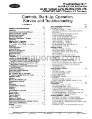
RETURN<br />
FLUID<br />
RETURN<br />
FLUID<br />
To configure the two chillers for operation, follow the<br />
example shown in Tables 24A <strong>and</strong> 24B. The master chiller will<br />
be configured with a slave chiller at address 2. Also in this example,<br />
the master chiller will be configured to use Lead/Lag<br />
Balance to even out the chiller runtimes weekly. The Lag <strong>Start</strong><br />
Delay feature will be set to 10 minutes. The chillers will be<br />
configured for parallel fluid flow. The master <strong>and</strong> slave chillers<br />
cannot have the same CCN address (CCNA, Configuration<br />
mode under OPT2). In addition, the chillers must be connected<br />
together on the same CCN bus. Connections can be made to<br />
the CCN screw terminals on TB3 in both chillers. The master<br />
chiller will determine which chiller will be Lead <strong>and</strong> which<br />
will be Lag. The master chiller controls the slave chiller by<br />
forcing the slave chiller ON <strong>and</strong> OFF, <strong>and</strong> forcing the control<br />
RUN<br />
STATUS<br />
SERVICE<br />
TEST<br />
TEMPERATURES PRESSURES<br />
Auto Manual<br />
Unit<br />
Ckt A<br />
Display Mode Temperatures Pressures<br />
(VIEW) On/Off<br />
(TEST)<br />
(UNIT) (PRC.A)<br />
Machine Ckt A/B Ckt A<br />
Ckt B<br />
Hours/<strong>Start</strong>s Outputs Temperatures Pressures<br />
(RUN) (OUTS) (CIR.A) (PRC.B)<br />
Compressor Compressor Ckt B<br />
Run Hours Tests Temperatures<br />
(HOUR) (COMP) (CIR.B)<br />
Compressor<br />
<strong>Start</strong>s<br />
(STRT)<br />
Software<br />
Version<br />
(VERS)<br />
LEGEND<br />
Ckt — Circuit<br />
SLAVE<br />
CHILLER<br />
MASTER<br />
CHILLER<br />
SLAVE<br />
CHILLER<br />
MASTER<br />
CHILLER<br />
LEAVING<br />
FLUID<br />
Fig. 11 — Dual Chiller Piping Arrangement<br />
(Series Fluid Flow)<br />
THERMISTOR<br />
WIRING*<br />
LEAVING<br />
FLUID<br />
INSTALL DUAL CHILLER LWT<br />
LEAVING FLUID TEMPERATURE<br />
THERMISTOR (T9) HERE<br />
* Depending on piping sizes, use either:<br />
HH79NZ014 sensor/10HB50106801 well (3-in. sensor/well)<br />
HH79NZ029 sensor/10HB50106802 well (4-in. sensor/well)<br />
Fig. 12 — Dual Chiller Thermistor Location<br />
Parallel Fluid Flow<br />
Table 11 — Navigator Display Menu Structure<br />
SET<br />
POINTS<br />
Cooling<br />
(COOL)<br />
Heating<br />
(HEAT)<br />
Head<br />
Pressure<br />
(HEAD)<br />
20<br />
point of the slave chiller. The master chiller will also split<br />
dem<strong>and</strong> limiting function appropriately between the two<br />
chillers, if dem<strong>and</strong> limiting is enabled.<br />
The master chiller is now configured for dual chiller operation.<br />
To configure the slave chiller, only the LLEN, PARA <strong>and</strong><br />
MSSL variables need to be set. Enable the Lead/Lag chiller<br />
variable (LLEN) as shown in Tables 24A <strong>and</strong> 24B. Similarly,<br />
set the Master/Slave Select variable (MSSL) to SLVE. The parallel<br />
variable (PARA) must be configured the same as the<br />
master chiller. The slave chiller does not use the variables<br />
LLBL, LLBD <strong>and</strong> LLDY.<br />
It is recommended to set the cooling set points to the same<br />
setting on both Master <strong>and</strong> Slave chillers for series flow<br />
(Duplex) applications. If outdoor air reset is required the<br />
outdoor air thermistor must be connected to the Slave chiller<br />
(TB5 term. 7 <strong>and</strong> 8). Outdoor Air Broadcast (BCST, OAT.B)<br />
must be configured “ON”. Remote contacts should be connected<br />
to both Master <strong>and</strong> Slave to control unit operation. Optional<br />
control inputs <strong>and</strong> Energy Management Module (EMM)<br />
should be connected to the Master chiller.<br />
INPUTS OUTPUTS CONFIGURATION<br />
Unit<br />
Discrete<br />
(GEN.I)<br />
Ckt A/B<br />
(CRCT)<br />
Unit<br />
Analog<br />
(4-20)<br />
Unit<br />
Discrete<br />
(GEN.O)<br />
Ckt A<br />
(CIR.A)<br />
Ckt B<br />
(CIR.B)<br />
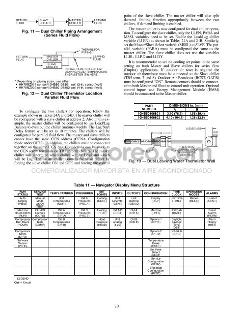
PART<br />
DIMENSIONS in. (mm)<br />
NUMBER<br />
A B<br />
10HB50106801 3.10 (78.7) 1.55 (39.4)<br />
10HB50106802 4.10 (104.1) 1.28 (32.5)<br />
A<br />
1/4 N.P.T.<br />
Display<br />
(DISP)<br />
Machine<br />
(UNIT)<br />
B<br />
Options 1<br />
(OPT1)<br />
Options 2<br />
(OPT2)<br />
Temperature<br />
Reset<br />
(RSET)<br />
Set Point<br />
Select<br />
(SLCT)<br />
<strong>Service</strong><br />
Configuration<br />
(SERV)<br />
Broadcast<br />
Configuration<br />
(BCST)<br />
TIME<br />
CLOCK<br />
Unit Time<br />
(TIME)<br />
Unit Date<br />
(DATE)<br />
Daylight<br />
Savings<br />
Time<br />
(DST)<br />
Schedule<br />
(SCHD)<br />
0.505/0.495<br />
6” MINIMUM<br />
CLEARANCE FOR<br />
THERMISTOR<br />
REMOVAL<br />
Fig. 13 — Dual Leaving Water Thermistor Well<br />
OPERATING<br />
MODES<br />
Modes<br />
(MODE)<br />
0.61<br />
DIA<br />
ALARMS<br />
Current<br />
(CRNT)<br />
Reset<br />
Alarms<br />
(RCRN)<br />
Alarm<br />
History<br />
(HIST)