Controls Start-Up, Operation, Service, and ... - Climayoreo
Controls Start-Up, Operation, Service, and ... - Climayoreo
Controls Start-Up, Operation, Service, and ... - Climayoreo

You also want an ePaper? Increase the reach of your titles
YUMPU automatically turns print PDFs into web optimized ePapers that Google loves.
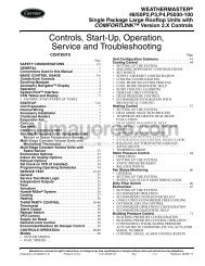
HPS<br />
LEGEND<br />
RRS<br />
HPS — High-Pressure Switch<br />
RRS — Reverse Rotation Switch (HK01CB002)<br />
Fig. 32 — Reverse Rotation Switch Wiring<br />
24. Locate the appropriate compressor item (‘CC.A1’, etc.)<br />
under the COMP sub-mode <strong>and</strong> start the compressor.<br />
Press ENTER , followed by to change the value to On,<br />
<strong>and</strong> then ENTER again. Once the compressor has success-<br />
fully started, energize both loaders one at a time. Let the<br />
circuit stabilize with both loaders energized. Refer to the<br />
Refrigerant Charging/Adding Charge <strong>and</strong> Oil Charging/<br />
Low Oil Recharging sections of this document for<br />
recharging procedures <strong>and</strong> performance criteria.<br />
25. Once proper rotation has been verified, disconnect <strong>and</strong><br />
lock out the power to the chiller. The reverse rotation low<br />
pressure switch can now be removed from the compressor<br />
<strong>and</strong> high pressure switch circuit.<br />
BURNOUT CLEAN-UP PROCEDURE — If a screw compressor<br />
motor burns out on a 30GX,HX chiller, a simple cleanup<br />
should be performed. The following procedure provides the<br />
minimum steps to be taken before restarting the circuit.<br />
1. Remove the oil from the oil separator. This can be facilitated<br />
by connecting a hose to the port located on the<br />
service valve entering the external oil filter. Run the hose<br />
to a container(s) that can hold up to 5 to 6 gallons (19 to<br />
20 L) of oil. Pressurize the circuit to force out most of the<br />
oil in the separator. To remove the remaining oil, the<br />
pre-lube pump can be run in the <strong>Service</strong> Test mode from<br />
the Navigator. Enable the desired pump (either item<br />
‘OL.P.A’ or ‘OL.P.B’ in the OUTS sub-mode). To prevent<br />
wear to the pump components, do not allow the prelube<br />
pump to operate “dry.”<br />
2. Remove the failed compressor following the Compressor<br />
Changeout Sequence procedure on page 57.<br />
3. Once the compressor is removed access the oil catch pan<br />
through the cooler-compressor mounting flange. Clean<br />
out any debris which may have collected in the oil catch<br />
pan.<br />
4. Install a new compressor.<br />
5. To dilute <strong>and</strong> remove any residual oil left in the separator,<br />
pump approximately 1 /2 gallon (2 L) of compressor oil<br />
into the oil separator using the Schrader port located on<br />
top of the separator (30GXN,R) or on the discharge line<br />
(30HXA,HXC) <strong>and</strong> remove using the pre-lube pump<br />
describedinStep1.<br />
6. Disconnect the hose from the external oil filter service<br />
valve.<br />
7. Install a new filter drier core <strong>and</strong> compressor external oil<br />
filter. If desired, a burnout (activated carbon) core may be<br />
used, but should be replaced with a st<strong>and</strong>ard filter drier<br />
core during the next filter replacement.<br />
8. Measure in the amount of Castrol SW 220 Polyolester oil<br />
as specified on the nameplate of the chiller.<br />
9. Leak check, evacuate <strong>and</strong> recharge the machine as<br />
described in this manual with the amount of R-134a<br />
stated on the chiller nameplate.<br />
10. Perform periodic acid checks on the circuit <strong>and</strong> change<br />
the filter drier core in the liquid line as necessary. Use the<br />
Carrier St<strong>and</strong>ard <strong>Service</strong> Techniques Manual as a source<br />
of reference.<br />
59<br />
Moisture-Liquid Indicator — Clear flow of liquid<br />
refrigerant indicates sufficient charge in the system. Note,<br />
however, that bubbles in the sight glass do not necessarily indicate<br />
insufficient charge. Moisture in the system is measured in<br />
parts per million (ppm), changes of color of indicator are:<br />
Green — moisture is below 80 ppm;<br />
Yellow-green (chartreuse) — 80 to 225 ppm (caution);<br />
Yellow (wet) — above 225 ppm.<br />
Change filter drier at the first sign of moisture in the system.<br />
IMPORTANT: Unit must in operation for at least<br />
12 hours before moisture indicator can give an accurate<br />
reading. With the unit running, the indicating element<br />
must be in contact with liquid refrigerant to give true<br />
reading.<br />
Filter Drier — Whenever moisture-liquid indicator shows<br />
presence of moisture, replace filter drier core. Refer to Carrier<br />
St<strong>and</strong>ards <strong>Service</strong> Technique Manual, Chapter 1, Refrigerants,<br />
for details on servicing filter driers. Cleanable strainers have<br />
been installed in each circuit’s liquid line to aid in removal of<br />
system contaminants <strong>and</strong> debris.There is one industry st<strong>and</strong>ard<br />
drier core in each strainer. See Fig. 33.<br />
Liquid Line <strong>Service</strong> Valve — This valve is located<br />
ahead of the filter drier <strong>and</strong> provides a 1 /4-in. Schrader connection<br />
(30GXN,R only) for field charging. In combination with<br />
compressor discharge service valve, each circuit can be<br />
pumped down into the high side for servicing.<br />
Thermistors — To aid in verifying thermistor performance,<br />
resistances at various temperatures are listed for all<br />
thermistors (except motor thermistors) in Tables 38A-39B. See<br />
Table 40 for motor thermistor values.<br />
LOCATION — General location of thermistor sensors <strong>and</strong><br />
terminal connections in the control box are listed in Table 3.<br />
THERMISTOR REPLACEMENT<br />
All thermistors are installed in wells <strong>and</strong> will slide out of<br />
the wells easily. The wells are under refrigerant pressure<br />
(cooler EWT <strong>and</strong> LWT are under waterside pressure) <strong>and</strong><br />
do not need to be removed to replace a faulty thermistor.<br />
To Replace Thermistors T1, T2, T3, T4, T5, or T6 (Entering,<br />
Leaving Water; Discharge Gas Temperature) — Disconnect<br />
appropriate connector from the Main Base Board<br />
(MBB) or Screw Compressor Board (SCB). Thermistors T1<br />
<strong>and</strong> T2 are connected to MBB-J8 <strong>and</strong> thermistors T3 through<br />
T6 are connected to EXV-J5. These six thermistors use insulation<br />
displacement connectors. New thermistors should be<br />
spliced to existing wiring close to the connector unless new<br />
connectors are required. A special AMP crimping tool, part no.<br />
58580-1, is needed if new connectors are used. Remove<br />
thermistor cable from harness. Remove <strong>and</strong> discard original<br />
thermistor from well. Insert new thermistor in well body to its<br />
full depth. Add a small amount of thermal conductive grease to<br />
thermistor probe <strong>and</strong> well. Thermistors are friction-fit<br />
thermistors <strong>and</strong> will slip back into well located at the cooler<br />
head (T1, T2) or at the top of each compressor discharge line<br />
(T3 through T6). Secure thermistor to well body with a wire tie<br />
to prevent thermistor from working its way out of the well. See<br />
Fig. 34.