Power Cable Accessories
Power Cable Accessories
Power Cable Accessories

Create successful ePaper yourself
Turn your PDF publications into a flip-book with our unique Google optimized e-Paper software.
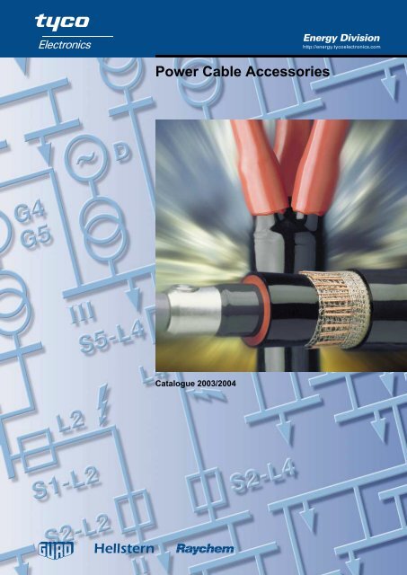
<strong>Power</strong> <strong>Cable</strong> <strong>Accessories</strong><br />
Catalogue 2003/2004<br />
Energy Division<br />
http://energy.tycoelectronics.com
Content<br />
Introduction 3<br />
Terminations – Low and Medium Voltage 15<br />
Connection Systems for gas-insulated<br />
Switchgear up to 24 kV 37<br />
Joints – Low Voltage 47<br />
Joints – Medium Voltage 67<br />
Sealing Systems 85<br />
Repair Sleeves and Tubings 93<br />
Tools and <strong>Accessories</strong> 101<br />
Connection Boxes 109<br />
1
Introduction<br />
Introduction<br />
General 4<br />
Low Voltage Jointing System 7<br />
Medium Voltage Terminations System 8<br />
Medium Voltage Jointing System 9<br />
Electrical Stress Control in <strong>Cable</strong> <strong>Accessories</strong> 10<br />
Weathering and Ageing Resistivity 11<br />
Technology of Heat-Shrinkable Products 12<br />
Advantages of Raychem Heat-Shrinkable Products 13<br />
3
4<br />
Tyco Electronics Energy Division<br />
We develop, manufacture and market innovative products which benefit from its<br />
advanced know-how in the field of material science. All products are designed to help<br />
our customers to improve the reliability and economy of their electrical networks and<br />
equipment. Our broad portfolio of products offered for the electrical power industry<br />
include cable accessories, surge arresters, insulators, insulation enhancement<br />
products, components for electrical equipment as well as connectors and fittings for up<br />
to 800 kV.<br />
This catalogue contains terminations, joints, connection boxes and accessories for<br />
cable types most commonly used in the electrical distribution and industrial networks of<br />
Central & Eastern Europe / CIS (change to your country!). As one of the largest<br />
suppliers of cable accessories in the world, Raychem products are offered for nearly all<br />
special and foreign cable constructions. Please contact the Raychem products<br />
representative for technical support and additional information about cable accessories<br />
or the other product lines.<br />
Raychem cable accessories<br />
As a result of sustained and extensive research and long experience in technical<br />
support work, Raychem products are developed during the last 3 decades to become a<br />
complete system of cable accessories up to 170 kV.<br />
The long-term performance of Raychem heat-shrinkable materials has been<br />
demonstrated by the well-proven Raychem accessory system. Millions of installations in<br />
some of the most severe service conditions have confirmed the reliability of the<br />
Raychem heat-shrinkable technique under high electrical, thermal and environmental<br />
stress.<br />
The technology that is common to all Raychem heat-shrinkable cable accessories is<br />
based on radiation crosslinked polymers with an elastomeric shape memory. They<br />
provide a significantly improved mechanical, chemical and thermal resistance compared<br />
to non-crosslinked products.<br />
Raychem cable accessories are distinguished by their good insulating and sealing<br />
characteristics, high mechanical toughness and resistance to weathering and<br />
chemicals, such as UV radiation and alkaline soils. Because of the large shrink area of<br />
the individual parts, it is possible to use a few standard accessories to cover a large<br />
range of different cable types and cross sections. This means that warehousing is<br />
simple and economical. In addition, Raychem cable accessories can be stored for an<br />
unlimited length of time under normal conditions.<br />
The product line includes indoor and outdoor terminations, inline and transition joints as<br />
well as universal insulation, sealing and repair systems for use in the cable network. All<br />
medium voltage accessories include a stress control system either as separate stress<br />
control tubing or integrated as stress control coating in an insulating tubing. In<br />
terminations, the insulating tubing ensures a non-tracking and erosion resistant surface<br />
and provides an environmental seal to the cable lug and the oversheath. The<br />
connection area of joints is covered by an elastomeric dual-wall tubing which provides<br />
an interface free insulation and an outer screening.
Installation<br />
No special tools are required for the cable preparation. The installation of the heatshrinkable<br />
parts is performed with a propane gas torch which is usually also used for<br />
the preparation of paper and plastic cables. When delivered, all individual parts are<br />
stretched so far that they can easily be slid over the prepared cable end. When<br />
sufficiently heated, they shrink and firmly enclose the cable and protect it against<br />
moisture, while the adhesive melts and fills all grooves and voids. Raychem cable<br />
accessories are constructed in a similar way to the cables themselves and can, like<br />
these, be bent in narrow spaces. Upside-down installations of terminations are possible<br />
simply by turning the heat-shrinkable sheds. The accessories can immediately put into<br />
operation after installation.<br />
Test process and qualification<br />
Raychem cable accessories are designed and fully tested to meet Raychem<br />
specification PPS 3013 which encompasses the requirements of major national and<br />
international standards, e.g.: IEC, CENELEC, GOST, BS CSN, MSZ, PN, STN, STR,<br />
VDE, etc. Test reports are available which document the tests performed in test<br />
institutes and in Raychem laboratories on the long-term electrical and environmental<br />
behaviour of cable accessories and materials.<br />
The currently relevant CENELEC standards tested to are:<br />
HD623.S1:1995 – Specifications for joints, stop ends and outdoor terminations for<br />
distribution cables of rated voltage 0,6/1,0 (1.2) kV<br />
HD629.1.S1:1996 – Test requirements on accessories for use on power cables of rated<br />
voltages from 3,6/6 (7,2) kV up to 20,8/36 (42) kV.<br />
Part 1: <strong>Cable</strong>s with extruded insulation.<br />
HD629.2.S1:1997 – Test requirements on accessories for use on power cables of rated<br />
voltages from 3,6/6 (7,2) kV up to 20,8/36 (42) kV.<br />
Part 2: <strong>Cable</strong>s with impregnated paper insulation.<br />
For product testing and selection we follow the classifications for rated voltages<br />
Uo/U (Um) as referred to in IEC and Cenelec standards:<br />
Uo is the rated power-frequency voltage between phase conductor and earth or<br />
metallic screen for which the cable accessory is designed.<br />
U is the rated power-frequency voltage between phase conductors for which the<br />
cable accessory is designed.<br />
Um is the maximum value of the ‘highest system voltage’ for which the cable accessory<br />
may be used.<br />
To cover all typical voltages in distribution networks, Tyco Electronics Energy Division<br />
tests cable accessories to the highest sets of rated voltages: 3,8/6,6 (7,2) kV<br />
6,35/11 (12) kV, 8,7/15 (17,5) kV, 12,7/22 (24) kV, 19/33 (36) kV and 20,8/36 (42).<br />
The quality standards of all materials throughout the entire manufacturing process<br />
beginning with the raw materials and continuing through to the packaged product are<br />
continuously monitored and documented. Materials as well as complete accessories are<br />
regularly requalified. As a result of our well established Quality Management System<br />
including quality assurance, Tyco Electronics Energy Division was one of the first in the<br />
industry to achieve a certification according to ISO 9001.<br />
Service<br />
Even the best technology can be applied in the wrong way. To avoid such situations, we<br />
have established a technical support service to provide technical information and<br />
application guidelines for our customers, such as cable fitters, project and maintenance<br />
engineers, constructors, equipment manufacturers and specification and purchasing<br />
engineers.<br />
A sound and practice oriented range of services is provided:<br />
O Presentations and Seminars<br />
O Technical papers focusing on<br />
new industry trends and products<br />
O Training in cable preparation, installation techniques<br />
and product selection for engineers and installers<br />
O Practical demonstrations and field installations<br />
O Solutions to specific customer problems<br />
5
6<br />
Quality Standards, Environment, Health and Safety<br />
The quality standards of all materials throughout the entire manufacturing process<br />
beginning with the raw materials and continuing through to the packaged product are<br />
continuously monitored and documented. Materials as well as complete accessories are<br />
regularly requalified. As a result of our well established Quality Management System<br />
including quality assurance, Tyco Electronics Energy Division continuously achieves recertification<br />
according to ISO 9001.<br />
Regular installations of Raychem heat-shrinkable cable accessories are considered to<br />
present no risk to health based on investigations by independent test institutes and<br />
customer evaluations. Moreover, hazards typically associated with cable accessory<br />
installations can be eliminated by avoiding any soldering or handling of conventional<br />
2 component or bitumen fillers. No messy or harmful residues requiring special or costly<br />
disposal are left over after installation.<br />
Only ecologically sound and recyclable components are used and packaging materials<br />
are continuously reduced. Our efforts and investments over the years in improving the<br />
environment led not only to the elimination of ozone-depleting materials and substantial<br />
reductions of waste materials and water consumption but also to new processes<br />
allowing crosslinked materials to be recycled. As a result of these efforts, we have<br />
successfully completed the environmental assessment in accordance with ISO 14001<br />
and received a certification as one of the first companies in the industry.<br />
Ordering and delivery<br />
All cable accessories come complete with the necessary electrical insulation materials,<br />
installation instructions (in local language) and a bill of material. Solderless earth<br />
connections are either included in the kits or can be ordered separately. <strong>Cable</strong> lugs and<br />
connectors are only included if specifically stated. Medium voltage termination kits and<br />
joint kits for 3-core cables include materials for all 3 phases, joint kits for single core<br />
cables only material for one phase.<br />
We continuously monitor delivery performance and lead times, look for opportunities<br />
to shorten cycle times and improve service. We also analyse our responsiveness<br />
throughout our distribution network to customers. This is not static, but rather a<br />
constantly improving process directed towards our goal: complete customer satisfaction.
Raychem Low Voltage Jointing System<br />
With extensive application over the last decades, the Raychem jointing system for mechanical or crimp connectors is widely used and<br />
acknowledged as a highly dependable and easy-to-install jointing method for conventional and modern cable types. The principle of<br />
the construction and the simple way of installation are described with a joint for 1 kV plastic insulated cables.<br />
Installation<br />
After preparation of the cable ends according to the installation instruction, the smaller<br />
inner tubings as well as the outer tubing are slipped over the cores.<br />
The conductors are now connected with mechanical or crimp connectors.<br />
All joints are designed to allow crossing of the cable cores.<br />
The inner tubings are positioned over the connectors and shrunk down to tightly fit the<br />
connectors and the core insulation ensuring an adequate wall thickness even around<br />
the more bulky mechanical connectors. At the same time the heat causes the adhesive,<br />
precoated on the inside of the tubings, to melt and flow. The resulting bond seals out<br />
moisture and corrosion and conforms to the thermal expansion of the cable.<br />
The outer tubing is positioned over the jointing area and shrunk. The mechanical and<br />
sealing functions of the oversheath are assured by this thick-walled tubing. A durable<br />
and repeatable seal is produced by means of a hot-melt adhesive pre-applied to the<br />
entire length of the tubing.<br />
The joint is complete and can be put into operation immediately.<br />
Construction<br />
1Outer tubing: Thick-wall protection<br />
against mechanical stresses and<br />
against moisture by sealing onto the<br />
oversheath.<br />
2 Inner tubings: Thick wall tubing<br />
providing electrical insulation and<br />
protection of the connection area<br />
against moisture inside the cable.<br />
3 Hot-melt adhesive<br />
1 3<br />
3 2<br />
7
Raychem Medium Voltage Termination System<br />
8<br />
1<br />
2<br />
3<br />
4<br />
1<br />
5<br />
Raychem developed during the 60’s a series of new polymers for use at medium and<br />
high voltage. The resulting materials possess exceptional resistance to prolonged<br />
electrical stress and weathering, but are also capable of being shrunk down quickly to fit<br />
and seal a cable. Raychem accessories provide an universal system of indoor and<br />
outdoor terminations for paper or plastic insulated cables, for single or three core<br />
cables, for cables with round or sector shaped conductors and most types of screening<br />
or armouring.<br />
The following describes the typical modules of a modern medium voltage termination:<br />
1Moisture sealing<br />
Durable sealing is achieved by special Raychem sealants on the inside of non-tracking,<br />
weather-resistant components. At the same time as the installer heats the tubings, the<br />
shrinking action causes the sealant to melt and flow into place.<br />
In case of three core cables, a sealant-lined heat-shrinkable breakout installed over the<br />
cores and cable crutch provides a sealed and weather-resistant surface from the<br />
connecting lugs to the oversheath.<br />
2 Compact and versatile stress control<br />
To meet the need for space-saving, flexible termination design, adaptable to different<br />
types of compact equipment, we developed a Raychem material with a carefully<br />
controlled non-linear impedance based on ceramic semiconductor technology (ZnO),<br />
which is applied in the form of a coating inside the tubing. When the tubing is shrunk,<br />
the stress control coating is softened by the applied heat and conforms and bonds to<br />
even irregular insulation surfaces to ensure a void free contact. Details of electrical<br />
stress control in Raychem terminations can be found on page 10.<br />
3 Non-tracking insulation tubing<br />
The superior non-tracking characteristics and long-term erosion resistance of Raychem<br />
terminations have been exhaustively demonstrated in comparative tests at major<br />
independent laboratories and Raychem’s own extensive development facilities. These<br />
results are borne out by the continuing performance of over a million units installed in<br />
tropical, desert, arctic and industrially polluted climates, confirming that Raychem<br />
terminations do not track even in severe service conditions and verifying their<br />
exceptional erosion resistance and reliability. The phenomenon of tracking and erosion<br />
is explained on page 11.<br />
4 Yellow void filler<br />
The semi-conducting void filler is easily applied in form of a short adhesive tape. It<br />
ensures that, independent of the type of semi-conductive screen or removal method, no<br />
air voids can cause discharges in the high stress area of the screen end.<br />
5 Earthing<br />
Earthing wires or braids are imbedded in the sealing mastic to prevent any corrosion by<br />
moisture ingress. For cables with tape screen or metal sheaths with armour solderless<br />
earthing systems are either provided within the termination kit or can be ordered<br />
separately.
Raychem Medium Voltage Jointing System<br />
Product design<br />
The design of a single-core joint for a<br />
polymeric insulated cable is described<br />
here. The same design principles are<br />
used for 3-core cables. For transition<br />
joints, special oil barrier tubings are used<br />
to transform draining oil (MI) as well as<br />
non draining oil (MIND) paper insulated<br />
cable into a quasi polymeric insulated<br />
cable with a radial field.<br />
Installation procedure<br />
The elastomeric joint component and the<br />
outer sealing sleeve are slid over the prepared<br />
cable end. The screen ends are<br />
electrically smoothed with a void filling<br />
compound and stress control tubings are<br />
shrunk over the cable ends. By simply<br />
tightening the bolts of the mechanical connector,<br />
the conductors are jointed and then<br />
covered with a stress control patch. The<br />
elastomeric component is quickly shrunk<br />
over the connection area. Roll springs and<br />
copper mesh rebuild the cable shield and<br />
the oversheath is replaced by an adhesive-coated<br />
sealing sleeve. All kits are<br />
supplied with illustrated step by step<br />
instructions.<br />
1 2 3 4<br />
1Electrical stress control<br />
The stress control tubing and the patch have a precisely defined impedance<br />
characteristic which smoothes the electrical field over the connector and cable screen<br />
ends. During installation of the tubings, its shrinking action compresses the special void<br />
filler (yellow) and the patch into position round the screen ends and the connector.<br />
Pencilling of the insulation at the connector is not necessary.<br />
2 Insulation and screen<br />
The elastomeric sleeve provides the correct thickness of insulation (red) in one step.<br />
The insulation screen is provided by the outer wall of the sleeve, which is of heatshrinkable<br />
conductive polymer (black). This technique saves installation time and<br />
ensures a flawless bond between joint insulation and screen.<br />
3 Metallic shielding<br />
Copper mesh and roll springs ensure the correct screen connection across the joint<br />
area and make electrical contact with the outer screen of the joint.<br />
4 Outer sealing and protection<br />
The heat used to shrink the outer sleeve causes the pre-coated adhesive to melt and<br />
flow, resulting in a lasting moisture and corrosion barrier on the cable oversheath. The<br />
outer sleeve provides mechanical impact and chemical resistance as expected from<br />
cable oversheaths. For armoured cables, Raychem joints incorporate a quick to install<br />
galvanised steel joint case or steel tape.<br />
Elastomeric technology – ECIC<br />
The elastomeric joint component is<br />
supplied in an expanded form, in which<br />
the heat-shrinkable outer wall holds the<br />
insulating at a wide diameter. Application<br />
of heat causes the outer wall to shrink,<br />
allowing the elastomeric, insulating layer<br />
to contract at the same time and closely fit<br />
the joint. Elastomers typically experience<br />
a reducing of the contraction force after<br />
storage and at cold temperatures. By<br />
applying heat this effect is overcome thus<br />
allowing an unlimited storage time and<br />
installations at low temperatures.<br />
The rubber-like characteristics of the<br />
insulation material combined with the rigid<br />
outer heat-shrinkable wall enable<br />
the joint to follow the thermally induced<br />
dimensional changes of the cable<br />
insulation.<br />
9
Electrical stress control in cable accessories<br />
Uncontrolled electrical field at the end<br />
of a cable<br />
At the end of medium voltage cables<br />
where the insulation screen is removed,<br />
the equipotential lines are very close<br />
indicating high electric stresses. This<br />
stress is high enough to ionise the air at<br />
the cable surface causing discharges.<br />
The temperature and by-products of this<br />
ionisation will, over a period of time,<br />
degrade the insulation surface. In<br />
addition, the stress at the screen end is<br />
that high that even the smallest notch<br />
would cause a breakdown.<br />
Electrical field with a stress control<br />
system (tubing or coating)<br />
Raychem terminations include stress<br />
control coatings or tubings with a carefully<br />
controlled volume resistivity and<br />
permitivity to smooth out the high stress<br />
areas. The electrical field strength at the<br />
end of the screen cut is reduced to a level<br />
well below the upper limit for long term<br />
operation.<br />
This slim stress control system can be<br />
used on a variety of cable types, including<br />
paper cables, and accommodates<br />
variations of cable dimensions.<br />
Non linear stress distribution<br />
The stress control coatings are made of a<br />
material which behaves similar to a varistor.<br />
The resulting voltage distribution is nonlinear<br />
and allows a short termination length<br />
while the electrical stress at the screen end<br />
area is kept low. In addition, the stress<br />
control coating is pressed into small surface<br />
irregularities by the shrinking action of the<br />
tubing. The result is a perfect interface fit<br />
over the insulation which prevents any<br />
discharge during operation. Most of the<br />
Raychem terminations include this stress<br />
control system.<br />
Linear stress distribution<br />
The non-linear impedance of the stress<br />
control tubing leads to a linear stress distribution<br />
(B). The resulting field depends<br />
on correct selection of material properties<br />
and length of the tubing. Improper selection<br />
of the materials impedance would<br />
lead to an unacceptable steep voltage rise<br />
at the screen end (A). Reducing the length<br />
or wrong positioning would result in discharge<br />
at the tubing end (C). All Raychem<br />
designed accessories take these effects<br />
into account.<br />
1 0<br />
Without stress control<br />
With stress control<br />
A – without stress control<br />
B – stress control coating<br />
A – improper impedance<br />
B – stress control tubing<br />
C – short length<br />
20%<br />
10%<br />
40% 50% 60% 70% 80%<br />
30%<br />
insulation screen core insulation<br />
insulation<br />
screen<br />
10% 20% 30% 40% 50% 60% 70%<br />
100%<br />
80%<br />
60%<br />
40%<br />
20%<br />
0%<br />
100%<br />
80%<br />
60%<br />
40%<br />
20%<br />
0%<br />
stress<br />
control<br />
layer<br />
A B<br />
A<br />
core insulation<br />
B C<br />
90%<br />
80%<br />
90%
Stress distribution insine a joint<br />
The stress control tubing contacts and<br />
overlaps the screen at each end of the<br />
joint and controls the stress at these<br />
areas in the same way as in terminations.<br />
Together with the high permitivity yellow<br />
void filler, the stress control tubing<br />
separates the equipotentials thus<br />
reducing the electrical stresses at the end<br />
of the connector. The single layer of<br />
insulation bonded to the outer conductive<br />
layer has a thickness designed to the<br />
rated voltage of the joint and prevents any<br />
interfacial discharge. The stress control<br />
system of this joint makes it unnecessary<br />
to chamfer the cable insulation or to use a<br />
connector with specially profiled shape.<br />
Weathering and ageing resistivity<br />
The excellent weathering and ageing<br />
resistance of Raychem cable accessories<br />
is continuously proven by natural and<br />
accelerated ageing tests. These tests<br />
include even 10 years lasting service<br />
tests with intensive UV radiation.<br />
Phenomenon of tracking and erosion<br />
Naturally over time, the surface of<br />
terminations, especially in outdoor<br />
applications, will become contaminated<br />
and leakage currents will develop in wet<br />
conditions. Under certain environmental<br />
conditions, these leakage currents can<br />
deteriorate the surface of a termination by<br />
building tracking paths or by erosion. Both<br />
would finally lead to a failure of the<br />
termination by breakdown.<br />
We have developed specially formulated<br />
Raychem insulation materials for heatshrinkable<br />
accessories which resist this<br />
phenomenon of tracking as well as other<br />
degrading factors like erosion, UV-light or<br />
other environmental stresses. This<br />
formulation consists of a blend of<br />
polymers and a sophisticated additive<br />
package which is designed to retain its<br />
performance over the lifetime even in the<br />
most severe environments.<br />
insulation screen joint insulation screen stress control tubing<br />
voltage<br />
earth<br />
voltage<br />
earth<br />
voltage<br />
earth<br />
joint insulation core insulation connector<br />
Film of<br />
conductive<br />
water<br />
Arcing which<br />
degrades<br />
the surface<br />
and forms a<br />
conductive<br />
path (carbon)<br />
Arcing<br />
bridging the<br />
dry zone<br />
voltage<br />
earth<br />
voltage<br />
earth<br />
voltage<br />
earth<br />
Evaporation<br />
caused by<br />
the leakage<br />
current<br />
Black<br />
conductive<br />
path<br />
of carbon<br />
voltage<br />
earth<br />
voltage<br />
earth<br />
voltage<br />
earth<br />
Dry zone<br />
Dry zone<br />
Tracking<br />
path<br />
Tracking path Long<br />
tracking<br />
path<br />
Breakdown<br />
1 1
Technology of Heat-Shrinkable Products<br />
Cross linking and Shape Memory<br />
Thermoplastic materials are composed of<br />
extremely long, very thin molecules in a<br />
random arrangement. The strength of<br />
such a material depends upon the<br />
distance between its molecules and the<br />
crystalline nature of its molecular<br />
structure. As the material is heated, these<br />
crystals disappear. The molecules can<br />
then slip past each other easily and the<br />
material flows. While in this heated<br />
condition the material may be formed into<br />
almost any desired shape. Then, when<br />
the material is subsequently allowed to<br />
cool, the crystals reform and again<br />
provide substantial strength to retain the<br />
plastic in the shape in which it has been<br />
formed.<br />
Manufacture and Installation of heat-shrinkable tubing<br />
Beaming the tubing causes permanent<br />
crosslinking of adjacent molecules. The<br />
graphic is an enlarged schematic view of<br />
a very small crosslinked section of<br />
extremely long molecules and an end<br />
view of a piece of heat-shrinkable tubing.<br />
While in this deformed position, the tubing<br />
is cooled; the crystals then reappear,<br />
thereby locking the structure together in<br />
this deformed condition indefinitely. This<br />
is the form in which tubing is supplied to<br />
customers.<br />
1 2<br />
With the advent of atomic energy, the<br />
important discovery was made that the<br />
exposure of some plastic materials to<br />
high-energy electron beams can cause<br />
the permanent crosslinking, or<br />
intermolecular joining, of adjacent<br />
molecules. This crosslinking results in the<br />
chemical bonding of the plastic structure<br />
into a new three-dimensional system.<br />
Once the tubing has been crosslinked,<br />
the next step in imparting elastic memory<br />
is to heat the compound above its<br />
crystalline melting point. The molecules<br />
are then tied together only by the<br />
crosslinks.<br />
The customer then heats the tubing,<br />
melting the crystals. The crosslinks allow<br />
the material to return to its original shape.<br />
Once the material has been crosslinked, it<br />
will not melt or flow at any temperature.<br />
When the material is heated, the crystals<br />
still disappear as before, but it will no<br />
longer flow or change shape because the<br />
crosslinks act as ties between the<br />
molecules. The crosslinked structure,<br />
however, is elastic. Thus, when it is<br />
heated to a temperature where the<br />
crystals have melted, the material<br />
behaves like rubber.<br />
While hot, the tubing is deformed by<br />
applying pressure, thus stretching the<br />
crosslinked molecule.<br />
After cooling, the crystals reform and the<br />
tubing is locked in its recovered form.
Advantages of Raychem heat-shrinkable products<br />
Properties Advantages Benefits<br />
Crosslinked material No shelf life No warehouse losses<br />
Mechanical resistance Long lifetime<br />
Chemical resistance Long lifetime<br />
Putting into service Reduced outage time<br />
immediately after installation<br />
Heat-shrinkable Excellent range taking Less stock required<br />
Independent of large cable tolerances Installation and operation reliability<br />
Use of hot melt adhesives Excellent sealing and<br />
operational reliability<br />
No reduction of shrink strength Installation reliability<br />
Possible to install at low temperatures Universal use<br />
Raychem design Exceeding specifications Operational reliability<br />
in demanding environments<br />
Fits on different cable types and Universal use<br />
sizes of different manufacturers<br />
Consistent installation procedures Installation reliability<br />
Tolerates typical variations of Installation reliability<br />
cable preparation in the field<br />
Non toxic and No health hazards Health and safety<br />
environmentally friendly<br />
Minor waste, environmentally friendly Low disposal cost<br />
Complete kits with Simple installation Operational reliability<br />
factory tested insulation<br />
Fast installation Reduced outage time<br />
Dual wall tubing: Improved interfaces Operational reliability<br />
elastomeric insulation/<br />
heat-shrinkable screen Reduced partial discharges Operational reliability<br />
Stress control tubing, Single piece, less risk of misplacement Operational reliability<br />
coating or patch<br />
Improved level of partial discharge Operational reliability<br />
1 3
1 4
Terminations<br />
Terminations – Low and Medium Voltage<br />
Terminations for polymeric and paper insulated<br />
cables 1 kV 16<br />
Terminations for belted, paper insulated cables<br />
(MI and MIND) with one common metal sheath<br />
6 kV and 10 kV 18<br />
Terminations for screened, paper insulated cables<br />
(MIND) with one metal sheath per phase<br />
10 kV, 20 kV and 35 kV 20<br />
Indoor terminations for screened, paper insulated (MI)<br />
cables with one metal sheath per phase<br />
10 kV and 20 kV 22<br />
Terminations for flexible, screened, rubber insulated<br />
cables 6 kV 24<br />
Terminations for unscreened, 3-core polymeric insulated<br />
cables 6 kV and 10 kV 26<br />
Terminations for screened, 3-core polymeric insulated<br />
cables 10 kV, 15 kV, 20 kV and 35 kV 28<br />
Terminations for screened, 1-core polymeric insulated<br />
cables 10 kV, 15 kV, 20 kV and 35 kV 30<br />
Elastomeric terminations for screened, 1-core polymeric<br />
insulated cables with wire screen<br />
10 kV, 15 kV, 20 kV and 35 kV 32<br />
Terminations for screened, polymeric insulated filter<br />
cables up to 150 kV D.C. 34<br />
Terminations for polymeric insulated cables for<br />
electrified Railway systems 25 kV A.C. 35<br />
1 5
Terminations for paper and polymeric insulated cables 1 kV<br />
<strong>Cable</strong><br />
The terminations are designed for 3- and<br />
4-core polymeric insulated cables with or<br />
without armour and 3- and 4-core paper<br />
insulated cables including cables with<br />
reduced neutral conductor.<br />
For example: NAYY, NAYBY,<br />
NAKBA,ВВГ, АВВГ, ПВГ, АПВГ, АпвВГб,<br />
ААБвУ, АСБУ, YAKY, XAKXS, KnFtA,<br />
AYKY, CYKY,CNKODY, ANKOY,<br />
ANKOPV, NAYY, NAYBY, NAKBA, PP<br />
00-A, XP 00-A,N(A)YY, PP 41-A,<br />
N(A)YBY, N(A)YC(W)Y,IPO 13, N(A)KBA.<br />
Design of terminations for<br />
polymeric cables<br />
The cable crutch is sealed by an adhesive<br />
lined heat-shrinkable breakout, which is<br />
installed over the cores and the end of the<br />
oversheath. Heat-shrinkable tubings seal<br />
between the cable lug and the end of the<br />
core insulation. All materials are resistant<br />
to UV-light and weathering. A solderless<br />
earth connection system consisting of a<br />
roll spring and an earth braid is included<br />
in terminations for armoured cables. In<br />
case UV-light protection of the core<br />
insulation is required, a CGPT insulating<br />
tubing can be ordered separately. All<br />
terminations can be ordered as complete<br />
kits or as components. Kits with the<br />
modification code -L12 include<br />
mechanical lugs with a busbar connection<br />
hole for M12 connection bolts, with code<br />
-L16 for M16 bolts.<br />
1 6<br />
L 1<br />
L 2<br />
L 3<br />
Dimensions L 1, L 2, L 3 see table page 17<br />
Design of terminations for<br />
paper cables<br />
The cores of the paper cable are covered<br />
with heat-shrinkable tubings. All materials<br />
are resistant to UV-light, weathering and<br />
cable oil. The cable cores can be cut to<br />
the required length at the place of<br />
installation. A heat-shrinkable breakout<br />
and tubings prevent any moisture ingress<br />
or oil leakage at the end of the metal<br />
sheath or of the cable cores. The kit<br />
includes a solderless earth connection<br />
system for the metal sheath, consisting of<br />
a roll spring, an earth braid, copper mesh<br />
and insulating tubing. The kit includes<br />
supplementary materials for cable<br />
preparation. Kits with the modification<br />
code -L12 include mechanical lugs with a<br />
busbar connection hole for M12<br />
connection bolts, with code -L16 for M16<br />
bolts.<br />
For 3-core cables<br />
The termination includes in addition a<br />
solderless neutral connection system for<br />
the aluminium sheath, consisting of<br />
stainless steel hose clamps, an earth<br />
braid and a mechanical lug.
Selection tables for polymeric insulated cables<br />
Complete terminations for 3- and 4-core plastic cables<br />
Terminations without lugs Terminations including mechanical lugs<br />
Cross Ordering description Cross Ordering description Dimensions<br />
section<br />
(mm<br />
for cables section for cables L3 L2 2 ) without armour with tape armour (mm2 ) without armour with tape armour (mm) (mm)<br />
4– 35 EPKT 0015 EPKT 0015-CEE01 95 50<br />
25– 70 EPKT 0031 EPKT 0031-CEE01 25– 70 EPKT 0031-L12 EPKT 0031-L12-CEE01 165 100<br />
70–150 EPKT 0047 EPKT 0047-CEE01 50–150 EPKT 0047-L12 EPKT 0047-L12-CEE01 215 100<br />
150–400 EPKT 0063 EPKT 0063-CEE01 120–240 EPKT 0063-L12 EPKT 0063-L12-CEE01 220 150<br />
Note: For 3-core cables the concentric neutral wires are sealed with sealing tape S1052-1-500 (length needed per termination approx.<br />
50 mm) and insulated with MWTM tubing (see table for paper cables). Sealing tape S1052 and MWTM tubing have to be ordered<br />
separately.<br />
Breakout and tubing components for plastic cable terminations<br />
Cross section Ordering description Cross section Ordering description Dimensions (mm)<br />
(mm2 ) Breakout Insulating tubing* (mm2 ) Lug sealing tubing L3 L2 1,5– 10 502S012/S CGPT 9/ 3-0 1,5– 10 MWTM 10/ 3- 50/S 60 50<br />
4– 35 502K033/S CGPT 12/ 4-0 4– 35 MWTM 16/ 5- 50/S 95 50<br />
25– 95 502K046/S CGPT 18/ 6-0 25– 70 MWTM 25/ 8-100/S 165 100<br />
50–150 502K016/S CGPT 24/ 8-0 70–150 MWTM 35/12-100/S 215 100<br />
120–400 502K026/S CGPT 39/13-0 150–400 MWTM 50/16-150/S 220 150<br />
* For outdoor terminations the cores can be protected against weathering and UV-light with the insulating tubing CGPT.<br />
Tubing lengths depend on the local installation requirements, technical and ordering details of MWTM and CGPT tubing see pages 98<br />
and 99. For single core cables only a lug sealing tubing is needed<br />
Selection tables for paper insulated cables<br />
Complete terminations for 3-core paper cables<br />
Cross Ordering description Dimensions (mm)<br />
section Core length L1 (mm)*<br />
(mm2 )<br />
without lugs<br />
250 x 4 = 1000 750 x 4 = 3000 1000 x 4 = 4000 L3 L2 25– 70 GUST 01/3x 25- 70/ 250 GUST 01/3x 25- 70/ 750 GUST 01/3x 25- 70/1000 165 80<br />
70–120 GUST 01/3x 70-120/ 250 GUST 01/3x 70-120/ 750 GUST 01/3x 70-120/1000 215 100<br />
120–240 GUST 01/3x120-240/ 250 GUST 01/3x120-240/ 750 GUST 01/3x120-240/1000 220 150<br />
including mechanical lugs<br />
25– 70 GUST 01/3x 25- 70/ 250-L12 GUST 01/3x 25- 70/ 750-L12 GUST 01/3x 25- 70/1000-L12 165 80<br />
70–120 GUST 01/3x 70-120/ 250-L12 GUST 01/3x 70-120/ 750-L12 GUST 01/3x 70-120/1000-L12 215 100<br />
120–240 GUST 01/3x120-240/ 250-L12 GUST 01/3x120-240/ 750-L12 GUST 01/3x120-240/1000-L12 220 150<br />
Note: All terminations kits include 1 mechanical lug for the neutral connection.<br />
* The core length L1 can be individually cut to the required length at the place of installation, minimum length is 100 mm. The sum of<br />
the core lengths L1 must not exceed 4 times the standard length L1 as given in the table.<br />
Complete terminations for 4-core paper cables<br />
Cross Ordering description Dimensions (mm)<br />
section Core length L1 (mm)*<br />
(mm2 )<br />
without lugs<br />
250 x 4 = 1000 750 x 4 = 3000 1000 x 4 = 4000 L3 L2 4– 25 GUST 01/4x 4- 25/ 250 GUST 01/4x 4- 25/ 750 GUST 01/4x 4- 25/1000 95 50<br />
16– 70 GUST 01/4x 16- 70/ 250 GUST 01/4x 16- 70/ 750 GUST 01/4x 16- 70/1000 165 80<br />
70–150 GUST 01/4x 70-150/ 250 GUST 01/4x 70-150/ 750 GUST 01/4x 70-150/1000 215 100<br />
120–240 GUST 01/4x120-240/ 250 GUST 01/4x120-240/ 750 GUST 01/4x120-240/1000 220 150<br />
including mechanical lugs<br />
25– 70 GUST 01/4x 25- 70/ 250-L12 GUST 01/4x 25- 70/ 750-L12 GUST 01/4x 25- 70/1000-L12 165 80<br />
70–150 GUST 01/4x 70-150/ 250-L12 GUST 01/4x 70-150/ 750-L12 GUST 01/4x 70-150/1000-L12 215 100<br />
120–240 GUST 01/4x120-240/ 250-L12 GUST 01/4x120-240/ 750-L12 GUST 01/4x120-240/1000-L12 220 150<br />
* The core length L1 can be individually cut to the required length at the place of installation, minimum length is 100 mm. The sum of<br />
the core lengths L1 must not exceed 4 times the standard length L1 as given in the table.<br />
Breakout and tubing components for paper cable terminations<br />
Cross section Ordering description Dimensions (mm)<br />
(mm 2 ) Breakout Insulating tubing* Lug sealing tubing L 3 L 2<br />
4– 25 502K033/S MWTM 10/ 3-A/U MWTM 16/ 5- 50/S 95 50<br />
16– 35 502K033/S MWTM 16/ 5-A/U MWTM 25/ 8-100/S 95 100<br />
35– 70 502K046/S MWTM 25/ 8-A/U MWTM 25/ 8-100/S 165 100<br />
70–150 502K016/S MWTM 25/ 8-A/U MWTM 35/12-100/S 215 100<br />
185–300 502K026/S MWTM 35/12-A/U MWTM 50/16-150/S 220 150<br />
* Tubing lengths depend on the local installation requirements, technical and ordering details of MWTM tubing see pages 98.<br />
Terminations and components for other cable types are available on request.<br />
1 7
Indoor terminations for belted, paper insulated cables (MI and MIND) with one<br />
common metal sheath 6 kV and 10 kV<br />
<strong>Cable</strong><br />
The indoor termination is designed for<br />
6 and 10 kV three core belted, paper<br />
insulated (MI, MIND) cables.<br />
For example: SB, ASB, SAAB, AABY,<br />
ASBY, ААБУ, АСБУ, СБ2лГ, АСБ2лГ,<br />
СБнГ, АСБнГ, АпвВГ, ПвПГ, Kny, KnFtly,<br />
AknFtA, AknFty, ANKOP, ANKOPV,<br />
CNKOY,CNKODY, IPO 13, IPO 14, NPO<br />
13, NPO 14, N(A)KBA, N(A)KLEY<br />
Design of termination<br />
The paper cores are covered with oil barrier<br />
tubing. The crutch is filled with an oil<br />
L<br />
Dimension L see table (L min = 450 mm) EPKT Termination only for MI cables<br />
resistive yellow mastic and is sealed with<br />
an adhesive lined, conductive breakout<br />
which is installed over the cores and the<br />
end of the metal sheath. Yellow stress<br />
control mastic is laid around the ends of<br />
breakout fingers and the cores are covered<br />
with red non-tracking tubing. The end<br />
of the termination is sealed either to the<br />
cable lug or to the solid conductor with a<br />
sealing boot. The kit includes a solderless<br />
earth connection. Kits with the modification<br />
code -L12 include mechanical lugs with a<br />
busbar connection hole for M12 connection<br />
bolts, with code -L16 for M16 bolts.<br />
Design of oil filled terminations<br />
for MI cables<br />
The cores are covered with brown,<br />
pressure-resistant, oil-barrier tubing. A<br />
transparent oil pot with heat-shrinkable<br />
moulded parts seals onto the oil barrier<br />
tubing and the metal sheath. The pot has<br />
to be filled with regular cable oil (not<br />
supplied with the termination). Adhesive<br />
coated sealing boots ensure an oil tight<br />
sealing to the cable lug. Solderless earth<br />
connections can be ordered separately.<br />
Termination for MI and MIND cables<br />
Nominal voltage Cross section Ordering description Dimension<br />
Uo/U (kV) (mm2 ) without cable lug with cable lug L (mm)<br />
GUST 12/ 25- 50/ 450 GUST 12/ 25- 50/ 450-L12 450<br />
25– 50 GUST 12/ 25- 50/ 800 GUST 12/ 25- 50/ 800-L12 800<br />
GUST 12/ 25- 50/1200 GUST 12/ 25- 50/1200-L12 1200<br />
3,5/6 GUST 12/ 70-120/ 450 GUST 12/ 70-120/ 450-L12 450<br />
and 70–120 GUST 12/ 70-120/ 800 GUST 12/ 70-120/ 800-L12 800<br />
6/10 GUST 12/ 70-120/1200 GUST 12/ 70-120/1200-L12 1200<br />
GUST 12/150-240/ 450 GUST 12/150-240/ 450-L12 450<br />
150–240 GUST 12/150-240/ 800 GUST 12/150-240/ 800-L12 800<br />
GUST 12/150-240/1200 GUST 12/150-240/1200-L12 1200<br />
Note: One termination kit includes material for 3 phases. Longitudinally sealed cable lugs are to be used.<br />
The core lengths can be reduced to the requirements at the place of installation, the minimum core length is 450 mm.<br />
Termination only for MI cables<br />
Nominal voltage Cross section Ordering description by length Dimension Solderless earth<br />
Uo/U (kV) (mm2 ) L = 550 mm L = 900 mm D (mm) connection<br />
16– 35 EPKT-4541 EPKT-4543 101 EAKT-1668-DE01<br />
3,5/6<br />
50–120<br />
150–240<br />
EPKT-4547<br />
EPKT-4559<br />
EPKT-4549<br />
EPKT-4561<br />
101<br />
125<br />
EAKT-1669-DE01<br />
EAKT-1670-DE01<br />
300–400 EPKT-4565 EPKT-4567 125 EAKT-1671-DE01<br />
16– 35 EPKT-4541 EPKT-4543 101 EAKT-1668-DE01<br />
6/10<br />
50– 95<br />
120–185<br />
EPKT-4547<br />
EPKT-4559<br />
EPKT-4549<br />
EPKT-4561<br />
101<br />
125<br />
EAKT-1669-DE01<br />
EAKT-1670-DE01<br />
240–300 EPKT-4565 EPKT-4567 125 EAKT-1671-DE01<br />
Note: Longitudinally sealed cable lugs are to be used. The core lengths can be reduced to the requirements at the place of<br />
installation, the minimum core length is 550 mm. Solderless earth connection must be ordered separately, it consists of 2 roll springs,<br />
earth lead, protection tubing and sealing adhesive.<br />
1 8
Outdoor terminations for belted, paper insulated cables (MI and MIND) with one<br />
common metal sheath 6 kV and 10 kV<br />
<strong>Cable</strong><br />
The outdoor termination is designed for<br />
6 and 10 kV three core belted, paper<br />
insulated (MI, MIND) cables.<br />
For example: SB, ASB, SAAB, ASBY,<br />
AABY, ААБУ, АСБУ, Kny, KnFtly,<br />
AknFtA, AknFty, ANKOP, ANKOPV,<br />
CNKOOY, CNKODY, ANKOY, IPO 13,<br />
IPO 14, NPO 13, NPO 14, N(A)KBA,<br />
N(A)KLEY<br />
Design of termination<br />
The paper cores are covered with oil<br />
barrier tubing. The crutch area is filled<br />
with an oil resistive yellow mastic and is<br />
sealed with an adhesive lined, conductive<br />
breakout which is installed over the cores<br />
and the end of the metal sheath. Yellow<br />
stress control mastic is laid around the<br />
ends of breakout fingers, and the cores<br />
are covered with red non-tracking tubing.<br />
The end of the termination is sealed<br />
either to the cable lug or to the solid<br />
conductor with a sealing boot. The kit<br />
includes a solderless earth connection.<br />
Kits with the modification code -L12<br />
include mechanical lugs with a busbar<br />
connection hole for M12 connection bolts,<br />
with code -L16 for M16 bolts.<br />
Nominal voltage Cross section Ordering description Dimension<br />
Uo/U (kV) (mm2 ) without cable lug with cable lug L (mm)<br />
GUST 12/ 25- 50/ 450 GUST 12/ 25- 50/ 450-L12 450<br />
25– 50 GUST 12/ 25- 50/ 800 GUST 12/ 25- 50/ 800-L12 800<br />
GUST 12/ 25- 50/1200 GUST 12/ 25- 50/1200-L12 1200<br />
GUST 12/ 70-120/ 450 GUST 12/ 70-120/ 450-L12 450<br />
3,5/6 70–120 GUST 12/ 70-120/ 800 GUST 12/ 70-120/ 800-L12 800<br />
GUST 12/ 70-120/1200 GUST 12/ 70-120/1200-L12 1200<br />
GUST 12/150-240/ 450 GUST 12/150-240/ 450-L12 450<br />
150–240 GUST 12/150-240/ 800 GUST 12/150-240/ 800-L12 800<br />
GUST 12/150-240/1200 GUST 12/150-240/1200-L12 1200<br />
25– 50<br />
6/10 70–120<br />
GUST 12/ 25- 50/ 800 GUST 12/ 25- 50/ 800-L12 800<br />
GUST 12/ 25- 50/1200 GUST 12/ 25- 50/1200-L12 1200<br />
GUST 12/ 70-120/ 800 GUST 12/ 70-120/ 800-L12 800<br />
GUST 12/ 70-120/1200 GUST 12/ 70-120/1200-L12 1200<br />
GUST 12/150-240/ 800 GUST 12/150-240/ 800-L12 800<br />
150–240<br />
GUST 12/150-240/1200 GUST 12/150-240/1200-L12 1200<br />
Note: One termination kit includes material for 3 phases. Longitudinally sealed cable lugs are to be used.<br />
The core lengths can be reduced to the requirements at the place of installation, the minimum core length is 450 mm<br />
for Uo/U = 3,5/6 kV and 800 mm for Uo/U = 6/10 kV.<br />
Explanation of MI and MIND:<br />
MI = Mass Impregnated = cable impregnated with draining compound<br />
MIND = Mass Impregnated Non Draining= cable impregnated with non draining compound<br />
L<br />
Dimension L see table<br />
(L min = 450 mm for Uo/U = 3,5/6 kV)<br />
(L min = 800 mm for Uo/U = 6/10 kV)<br />
1 9
Indoor terminations for screened paper insulated (MIND) cables with one metal<br />
sheath per phase 10 kV, 20 kV and 35 kV<br />
<strong>Cable</strong><br />
The indoor termination is designed for 20<br />
and 35 kV screened three and single core<br />
paper insulated (MIND) cables with one<br />
metal sheath per phase.<br />
For example: ЦАОСБУ, HAKnFtA,<br />
HAKNY, HknFty, AMKTQYPVsp.,<br />
AMKTOYPVsp., AOSB, NPZO 13,<br />
NPZOP 13, NPZO 23<br />
2 0<br />
Dimensions L, D see table<br />
Design of termination<br />
Yellow, oil resistant void filling tape is laid<br />
around the end of the metal sheath, and<br />
the paper cores are completely covered<br />
with oil barrier tubing. An oil resistant<br />
sealing boot ensures a pressure tight seal<br />
to the cable lug. A short conductive tubing<br />
rebuilds the screen from the metal sheath<br />
to the covered paper core.<br />
Yellow stress grading mastic is laid<br />
around the end of the conductive tubing<br />
and a stress control tubing is shrunk over<br />
the conductive tubing and the covered<br />
paper insulation. The end of the cores<br />
and the stress control tubing are insulated<br />
with non-tracking insulating tubing.<br />
Additional skirts are installed onto the<br />
tubing (see table). Solderless earth<br />
connections can be ordered separately.<br />
Nominal voltage Cross section Ordering description Dimensions (mm) No. of<br />
Uo/U (kV) (mm 2 ) L D skirts<br />
6/10<br />
35– 70<br />
95–240<br />
EPKT 24B1MI-CEE01<br />
EPKT 24C1MI-CEE01<br />
330<br />
330<br />
85<br />
95<br />
3 x 1<br />
3 x 1<br />
35– 50 EPKT 24B1MI-CEE01 330 85 3 x 1<br />
12/20 70–185 EPKT 24C1MI-CEE01 330 95 3 x 1<br />
240–300 EPKT 24D1MI-CEE01 330 115 3 x 1<br />
50– 95 EPKT 36C1MI-CEE01 430 95 3 x 2<br />
20/35 120–185 EPKT 36D1MI-CEE01 430 115 3 x 2<br />
240–500 EPKT 36E1MI-CEE01 430 115 3 x 2<br />
Note: One termination kit includes material for 3 phases. Longitudinally sealed cable lugs are to be used.<br />
Solderless earth connection<br />
Cross section Ordering description<br />
(mm2 ) three core cables single core cable single core cable<br />
including breakout with lead sheath with AL sheath<br />
35–150 EAKT 1678 EAKT 1668-DE01*<br />
70–150 EAKT 1678 EAKT 1668-DE01* SMOE 61832*<br />
150–240 EAKT 1679 EAKT 1669-DE01* SMOE 61832*<br />
* 3 Earth connection kits have to be ordered per termination kit.<br />
Note: The solderless earth connection kit must be ordered separately. The EAKT include roll springs, earth leads and protection<br />
tubings and a heat-shrinkable breakout for three-core cables. The SMOE kit includes a Ligarex connection system (see also tools at<br />
page 107).<br />
Explanation of MI and MIND:<br />
MI = Mass Impregnated = cable impregnated with draining compound<br />
MIND = Mass Impregnated Non Draining = cable impregnated with non draining compound<br />
D<br />
L
Outdoor terminations for screened, paper insulated (MIND) cables with one metal<br />
sheath per phase 10 kV, 20 kV and 35 kV<br />
<strong>Cable</strong><br />
The outdoor termination is designed for<br />
20 and 35 kV screened three and single<br />
core paper insulated (MIND) cables with<br />
one metal sheath per phase.<br />
For example: ЦАОСБУ, HAKnFtA,<br />
HAKNY, HknFty, AMKTQYPVsp.,<br />
AMKTOYPVsp., AOSB, NPZO 13,<br />
NPZOP 13, NPZO 23<br />
Dimensions L, D see table<br />
Design of termination<br />
Yellow, oil resistant void filling tape is laid<br />
around the end of the metal sheath and<br />
the paper cores are completely covered<br />
with oil barrier tubing. An oil resistant<br />
sealing boot ensures a pressure tight seal<br />
to the cable lug. A short conductive tubing<br />
rebuilds the screen from the metal sheath<br />
to the covered paper core. Yellow, stress<br />
grading mastic is laid around the end of<br />
the conductive tubing, and a stress<br />
Nominal voltage Cross section Ordering description Dimensions (mm) No. of<br />
Uo/U (kV) (mm2 ) L D skirts<br />
6/10<br />
35– 70<br />
95–240<br />
EPKT 24B1MO-CEE01<br />
EPKT 24C1MO-CEE01<br />
410<br />
410<br />
85<br />
95<br />
3 x 3<br />
3 x 3<br />
35– 50 EPKT 24B1MO-CEE01 410 85 3 x 3<br />
12/20 70–185 EPKT 24C1MO-CEE01 410 95 3 x 3<br />
240–300 EPKT 24D1MO-CEE01 410 115 3 x 3<br />
50– 95 EPKT 36C1MO-CEE01 560 95 3 x 4<br />
20/35 120–185 EPKT 36D1MO-CEE01 560 115 3 x 4<br />
240–500 EPKT 36E1MO-CEE01 560 115 3 x 4<br />
Note: One termination kit includes material for 3 phases. Longitudinally sealed cable lugs are to be used.<br />
Solderless earth connection<br />
Cross section Ordering description<br />
(mm2 ) three core cables single core cable single core cable<br />
including breakout with lead sheath with AL sheath<br />
35–150 EAKT 1678 EAKT 1668-DE01*<br />
70–150 EAKT 1678 EAKT 1668-DE01* SMOE 61832*<br />
150–240 EAKT 1679 EAKT 1669-DE01* SMOE 61832*<br />
* 3 Earth connection kits have to be ordered per termination kit.<br />
Note: The solderless earth connection kit must be ordered separately. The EAKT include roll springs, earth leads and protection<br />
tubings or a breakout. The SMOE kit includes a Ligarex connection system (see also tools at page 107).<br />
D<br />
L<br />
control tubing is shrunk over the<br />
conductive tubing and the covered paper<br />
insulation. The end of the cores and the<br />
stress control tubing are insulated with<br />
non-tracking insulating tubing. Additional<br />
skirts are installed onto the tubing (see<br />
table). Solderless earth connections can<br />
be ordered separately.<br />
2 1
Indoor terminations for screened, paper insulated (MI) cables with one metal sheath<br />
per phase 10 kV and 20 kV<br />
<strong>Cable</strong><br />
The indoor termination is designed for 10<br />
and 20 kV screened three and single core<br />
paper insulated (MI) cables with one<br />
metal sheath per phase.<br />
For example: AOUSZB, ЦАОСБУ,<br />
AOСБГУ, ОСБУ, ANKOY, CNKOY,<br />
ANKTOY-Vsp., ANKTOYP, AOUSZB,<br />
IPZO 13, IPZOP 13, IPZO 23, N(A)KLEY,<br />
N(A)HEKBA, N(A)EKBA<br />
2 2<br />
D<br />
Dimensions L, D see table<br />
Design of termination<br />
A metallic stress control cone is fixed with<br />
binding wire to the end of the metal<br />
sheath and screen cut. A transparent oil<br />
pot with heat-shrinkable moulded parts<br />
seals onto the cable lug and the metal<br />
sheath. The pot has to be filled with<br />
regular cable oil (not supplied with the<br />
termination). Solderless earth<br />
connections can be ordered separately.<br />
Nominal voltage Cross section Ordering description Dimensions (mm)<br />
Uo/U (kV) (mm2 ) L D<br />
50* IDST 5121-E11 300 71<br />
70* IDST 5121-E12 300 71<br />
70** IDST 5121 300 71<br />
6/10<br />
95 IDST 5121 300 71<br />
120–185 IDST 5122 300 71<br />
185–300 IDST 5122 300 71<br />
50* IDST 5121-E11 300 71<br />
70* IDST 5121-E12 300 71<br />
12/20 70** IDST 5121 300 71<br />
95–150 IDST 5122 300 71<br />
150–240 IDST 5123 300 71<br />
* Only for cables with Cu conductor (95 mm2 crimp cable lugs and reduction sleeves are included in the kit).<br />
** Only for cables with aluminium conductor.<br />
Note: One termination kit includes material for 3 phases. Longitudinally sealed cable lugs are to be used.<br />
The terminations can be filled with regular cable oil (not included). For filling funnels and cable oil see page 95.<br />
Solderless earth connection<br />
Cross section Ordering description<br />
(mm2 ) three core cables single core cable single core cable<br />
including breakout with lead sheath with AL sheath<br />
35–150 EAKT 1678 EAKT 1668-DE01*<br />
70–150 EAKT 1678 EAKT 1668-DE01* SMOE 61832*<br />
150–240 EAKT 1679 EAKT 1669-DE01* SMOE 61832*<br />
* 3 Earth connection kits have to be ordered per termination kit.<br />
Note: The solderless earth connection kit must be ordered separately. The EAKT include roll springs, earth leads and protection<br />
tubings or a breakout. The SMOE kit includes a Ligarex connection system (see also tools at page 107).<br />
Explanation of MI and MIND:<br />
MI = Mass Impregnated = cable impregnated with draining compound<br />
MIND = Mass Impregnated Non Draining = cable impregnated with non draining compound<br />
L<br />
min. 550
Long term testing of 10 kV paper cable<br />
accessories type GUSJ and GUST at<br />
Raychem products development<br />
laboratories.<br />
2 3
Indoor terminations for flexible, screened, rubber insulated cables 6 kV<br />
<strong>Cable</strong><br />
The termination is designed for 6 kV<br />
screened, flexible, rubber insulated cables<br />
with one or three earth cores.<br />
For example: NTSC, КГЭ, КГЭТ, Ogb,<br />
Ogc-G, CHCU, CBVU, EpN 64i65, EpN<br />
(BN) 64i74, EpN (BN) 76i78, EpN (BN)<br />
78/53.<br />
2 4<br />
Dimension L see table<br />
Design of termination<br />
Stress grading mastic is wrapped around<br />
the area of the screen cut. All cores are<br />
covered with non-tracking insulating<br />
tubing. The area between the end of the<br />
oversheath and the cores is sealed and<br />
protected by a 6- or 4-finger breakout. The<br />
cores remain flexible and can be bent like<br />
the cable.<br />
Terminations for other voltages or core lengths are available on request.<br />
Nominal voltage Cross section Ordering description by length<br />
Uo/U (kV) (mm2 )<br />
<strong>Cable</strong>s with 1 earth core<br />
L = 450 mm L = 1200 mm<br />
10/10– 70/ 70 EMKT 7A4IH2 EMKT 7A4IH5<br />
3,5/6<br />
95/95–185/185<br />
<strong>Cable</strong>s with 3 earth cores<br />
EMKT 7B4IH2 EMKT 7B4IH5<br />
25/10– 70/16 EMKT 7E6IH2 EMKT 7E6IH5<br />
95/16–185/35 EMKT 7F6IH2 EMKT 7F6IH5<br />
Note: One termination kit includes material for 3 phases.<br />
The core lengths can be reduced to the requirements at the place of installation, the minimum core length is 300 mm.<br />
Terminations for other voltages or core lengths are available on request.<br />
L<br />
D
Outdoor terminations for flexible, screened, rubber insulated cables 6 kV<br />
<strong>Cable</strong><br />
The termination is designed for 6 kV<br />
screened, flexible, rubber insulated cables<br />
with one or three earth cores.<br />
For example: NTSC, КГЭ, КГЭТ, Ogb,<br />
Ogc-G, CHCU, CBVU, EpN 64i65, EpN<br />
(BN) 64i74, EpN (BN) 76i78, EpN (BN)<br />
78/53.<br />
Design of termination<br />
Stress grading mastic is wrapped around<br />
the area of the screen cut. All cores are<br />
covered with non-tracking insulating tubing.<br />
The area between the end of the<br />
oversheath and the cores is sealed and<br />
protected by a 6- or 4-finger breakout.<br />
Outdoor terminations include in addition 2<br />
sheds per phase. The cores remain flexible<br />
and can be bent like the cable.<br />
Nominal voltage Cross section Ordering description by length D No. of<br />
Uo/U (kV) (mm2 )<br />
<strong>Cable</strong>s with 1 earth core<br />
L = 450 mm L = 1200 mm (mm) skirts<br />
10/10– 70/ 70 EMKT 7A4OH2 EMKT 7A4OH5 76 3 x 2<br />
3,5/6<br />
95/95–185/185<br />
<strong>Cable</strong>s with 3 earth cores<br />
EMKT 7B4OH2 EMKT 7B4OH5 85 3 x 2<br />
25/10– 70/16 EMKT 7E6OH2 EMKT 7E6OH5 76 3 x 2<br />
95/16–185/35 EMKT 7F6OH2 EMKT 7F6OH5 85 3 x 2<br />
Note: One termination kit includes material for 3 phases. Longitudinally sealed cable lugs are to be used.<br />
The core lengths can be reduced to the requirements at the place of installation, the minimum core length is 450 mm.<br />
Terminations for other voltages or core lengths are available on request.<br />
L<br />
Dimension L, D see table<br />
D<br />
2 5
Indoor termination for unscreened, 3-core polymeric insulated cables 6 kV and 10 kV<br />
<strong>Cable</strong><br />
The indoor termination is designed for 6 kV<br />
and 10 kV unscreened three core plastic<br />
insulated cables with armour or copper<br />
earth shield.<br />
For example: АПВГ, YAKYFtly, YKYFoY,<br />
YAKYFpy, AYKCY, CYKCY, NAYFGY, PP<br />
41-(A), PP 44-(A), PP45-(A), N(A)YFGY.<br />
2 6<br />
Dimension L see table<br />
Design of termination<br />
The cores are covered with non-tracking<br />
insulating tubing. The area between the<br />
end of the oversheath and the cores is<br />
sealed and protected by a non-tracking<br />
insulating breakout. Solderless earth<br />
connections can be ordered separately<br />
Nominal voltage Cross section Ordering description Dimension (mm)<br />
Uo/U (kV) (mm2 ) L<br />
EPKT 2041 450<br />
16– 50<br />
EPKT 2042<br />
EPKT 2043<br />
650<br />
800<br />
EPKT 2044 1200<br />
3,5/6 EPKT 2051 450<br />
and<br />
6/10<br />
70–120<br />
EPKT 2052<br />
EPKT 2053<br />
650<br />
800<br />
EPKT 2054 1200<br />
EPKT 2061 450<br />
150–240<br />
EPKT 2062<br />
EPKT 2063<br />
650<br />
800<br />
EPKT 2064 1200<br />
Note: One termination kit includes material for 3 phases.<br />
The core lengths can be reduced to the requirements at the place of installation, the minimum core length is 250 mm<br />
(450 mm for 10 kV).<br />
Solderless earth connection for cables with armour or copper tape shield<br />
Nominal voltage Cross section Ordering description<br />
Uo/U (kV) (mm2 )<br />
3,5/6<br />
16– 95<br />
120–300<br />
SMOE 60805<br />
SMOE 60873<br />
16 SMOE 60805<br />
6/10 25– 95 SMOE 60873<br />
120–300 SMOE 62176<br />
Note: The solderless earth connection kit must be ordered separately. It includes a roll spring and an earth lead.<br />
Terminations for motor connection boxes are available on request.<br />
L
Outdoor termination for unscreened, 3-core polymeric insulated cables<br />
6 kV and 10 kV<br />
<strong>Cable</strong><br />
The indoor termination is designed for 6 kV<br />
and 10 kV unscreened three core plastic<br />
insulated cables with armour or copper<br />
earth shield.<br />
For example: АПВГ , YAKYFtly, YKYFoy,<br />
YKYFtly, AYKCY, CYKCY, NAYFGY, PPO<br />
41-(A), PP 44-(A), PP45-(A), N(A)YFGY.<br />
Dimensions L, D see table<br />
Design of termination<br />
The cores are covered with non-tracking<br />
insulating tubing. The area between the<br />
end of the oversheath and the cores is<br />
sealed and protected by a non-tracking<br />
insulating breakout. Additional skirts are<br />
installed onto the tubing (see table).<br />
Nominal voltage Cross section Ordering description Dimensions (mm) No. of<br />
Uo/U (kV) (mm 2 ) L D skirts<br />
3,5/6<br />
16– 50<br />
EPKT 2292<br />
EPKT 2294<br />
650<br />
1200<br />
76<br />
76<br />
3 x 1<br />
3 x 1<br />
and<br />
6/10<br />
70–120<br />
EPKT 2302<br />
EPKT 2304<br />
650<br />
1200<br />
95<br />
95<br />
3 x 1<br />
3 x 1<br />
EPKT 2312 650 95 3 x 1<br />
150–240<br />
EPKT 2314 1200 95 3 x 1<br />
Note: One termination kit includes material for 3 phases. Longitudinally sealed cable lugs are to be used.<br />
The core lengths can be reduced to the requirements at the place of installation, the minimum core length is 450 mm.<br />
Solderless earth connection for cables with armour or copper tape shield<br />
Nominal voltage Cross section Ordering description<br />
Uo/U (kV) (mm2 )<br />
3,5/6<br />
16– 95<br />
120–300<br />
SMOE 60805<br />
SMOE 60873<br />
16 SMOE 60805<br />
6/10 25– 95 SMOE 60873<br />
120–300 SMOE 62176<br />
Note: The solderless earth connection kit must be ordered separately. It includes a roll spring and an earth lead.<br />
Terminations for motor connection boxes are available on request.<br />
Solderless earth connections can be<br />
ordered separately.<br />
2 7
Indoor termination for screened, 3-core polymeric insulated cables 10 kV, 15 kV, 20 kV<br />
and 35 kV<br />
Nominal Terminations without lugs Terminations with mechanical lugs<br />
voltage Cross Ordering description by length Cross Ordering description by length<br />
section section<br />
Uo/U (kV) (mm2 ) L = 450 mm L = 1200 mm (mm2 ) L = 450 mm L = 1200 mm<br />
10– 16 POLT-12A/3XI-H1 POLT-12A/3XI-H4<br />
25– 70 POLT-12C/3XI-H1 POLT-12C/3XI-H4 25– 50 POLT-12C/3XI-H1-L12 POLT-12C/3XI-H4-L12<br />
6/10 95–240 POLT-12D/3XI-H1 POLT-12D/3XI-H4 70–120 POLT-12D/3XI-H1-L12APOLT-12D/3XI-H4-L12A<br />
120–240 POLT-12D/3XI-H1-L12B POLT-12D/3XI-H4-L12B<br />
240–400 POLT-12E/3XI-H1 POLT-12E/3XI-H4<br />
35– 70 POLT-24C/3XI-H1 POLT-24C/3XI-H4 25– 50 POLT-24C/3XI-H1-L12 POLT-24C/3XI-H4-L12<br />
8,7/15 70–240 POLT-24D/3XI-H1 POLT-24D/3XI-H4 70–120 POLT-24D/3XI-H1-L12APOLT-24D/3XI-H4-L12A<br />
185–400 POLT-24E/3XI-H1 POLT-24E/3XI-H4 120–240 POLT-24D/3XI-H1-L12B POLT-24D/3XI-H4-L12B<br />
10– 25 POLT-24B/3XI-H1 POLT-24B/3XI-H4<br />
25– 50 POLT-24C/3XI-H1 POLT-24C/3XI-H4 25– 50 POLT-24C/3XI-H1-L12 POLT-24C/3XI-H4-L12<br />
12/20 70–185 POLT-24D/3XI-H1 POLT-24D/3XI-H4 50–120 POLT-24D/3XI-H1-L12APOLT-24D/3XI-H4-L12A<br />
120–185 POLT-24D/3XI-H1-L12B POLT-24D/3XI-H4-L12B<br />
185–400 POLT-24E/3XI-H1 POLT-24E/3XI-H4 185–300 POLT-24E/3XI-H1-L12 POLT-24E/3XI-H4-L12<br />
50–120 – POLT-42D/3XI-H4 50–120 – POLT-42D/3XI-H4-L12<br />
20/35 120–300 – POLT-42E/3XI-H4 120–300 – POLT-42E/3XI-H4-L12<br />
300–500 – POLT-42F/3XI-H4<br />
Note: The core lengths can be reduced to the requirements at the place of installation, the minimum core length is 320 mm for Uo/U =<br />
6/10 kV 360 mm for Uo/U = 12/20 kV and 600 mm for Uo/U = 20/35 kV. For terminations with mechanical lugs for M16 bolts use<br />
modification code -L16. Solderless earth connections for cables with tape screen have to be ordered separately.<br />
Solderless earth connection for copper tape shielded cables with or without armour<br />
Nominal voltage Cross section Ordering description for cables with tape shield<br />
Uo/U (kV) (mm2 ) without armour with tape armour with wire armour<br />
10– 50 EAKT-1655 – –<br />
6/10<br />
35–120<br />
95–240<br />
EAKT-1656<br />
EAKT-1657<br />
EAKT-1675-CEE01<br />
EAKT-1676-CEE01<br />
–<br />
EAKT-1657 + EAKT-1643<br />
240–500 EAKT-1658 EAKT-1677-CEE01 EAKT-1658 + EAKT-1645<br />
35– 95 EAKT-1656 EAKT-1675-CEE01 –<br />
8,7/15 70–185 EAKT-1657 EAKT-1676-CEE01 EAKT-1657 + EAKT-1643<br />
185–400 EAKT-1658 EAKT-1677-CEE01 EAKT-1658 + EAKT-1645<br />
25– 70 EAKT-1656 EAKT-1675-CEE01 –<br />
12/20 50–150 EAKT-1657 EAKT-1676-CEE01 EAKT-1657 + EAKT-1643<br />
120–400 EAKT-1658 EAKT-1677-CEE01 EAKT-1658 + EAKT-1645<br />
50–150 EAKT-1658 EAKT-1677-CEE01 EAKT-1658 + EAKT-1644<br />
20/35 50–300 EAKT-1658 EAKT-1677-CEE01 EAKT-1658 + EAKT-1645<br />
300–500 EAKT-1659 –<br />
Note: The solderless earth connection kit must be ordered separately. It includes 3 roll springs and 3 earth leads, for cables with tape<br />
armour in addition one larger roll spring. For cables with wire armour, it includes clamping rings, an earth lead and a sealing sleeve.<br />
2 8<br />
<strong>Cable</strong><br />
The indoor termination is designed for 10,<br />
15, 20 kV and 35 kV screened, three core<br />
plastic insulated cables with or without<br />
armour or copper tape shield.<br />
For example: N(A)YSEY, NA2XSY,<br />
N2XSEY, NA2XS2Y, АпвБ, АпвБШв,<br />
AXEKVCY, AXEKVCEY, N(A)2XSY, XHP<br />
81, EpHP 81, PHP 48,PHP 84, XHP 48.<br />
Design of termination<br />
The cable is transformed to quasi 3 single<br />
core cables which allows to cross the<br />
cores even in confined connection<br />
spaces. The cores are covered with<br />
conductive tubing from the crutch area<br />
close to the screen end. The crutch area<br />
is sealed and protected with an adhesive<br />
lined, conductive breakout which is<br />
installed over the cores and the end of the<br />
oversheath.Yellow stress grading mastic<br />
is laid around the end of the screen cut. A<br />
non-tracking insulating tubing coated with<br />
stress control and sealing mastic is<br />
installed between the end of the<br />
conductive tubing and the cable lug.<br />
Solderless earth connections for cables<br />
with tape shield or armour have to be<br />
ordered separately. Kits with the<br />
modification code -L12 include<br />
mechanical lugs with a busbar connection<br />
hole for M12 connection bolts, with code<br />
-L16 for M16 bolts.
Outdoor termination for screened, 3-core polymeric insulated cables<br />
10 kV, 15 kV, 20 kV and 35 kV<br />
Design of termination<br />
The design and installation is the same as<br />
for indoor terminations. In addition skirts<br />
are installed onto the tubing (see table).<br />
Solderless earth connections for cables<br />
with tape shield or armour have to be<br />
ordered separately.<br />
Kits with the modification code -L12<br />
include mechanical lugs with a busbar<br />
connection hole for M12 connection bolts,<br />
with code -L16 for M16 bolts.<br />
Dimensions L, D see table<br />
Terminations including mechanical lugs<br />
Nominal voltage Cross section Ordering description by length D No. of<br />
Uo/U (kV) (mm2 ) L = 450 mm L = 1200 mm (mm) skirts<br />
25– 50 POLT-12C/3XO-H1-L12 POLT-12C/3XO-H4-L12 85 3 x 1<br />
6/10 70–120 POLT-12D/3XO-H1-L12APOLT-12D/3XO-H4-L12A95 3 x 1<br />
120–240 POLT-12D/3XO-H1-L12B POLT-12D/3XO-H4-L12B 95 3 x 1<br />
25– 50 POLT-24C/3XO-H1-L12 POLT-24C/3XO-H4-L12 85 3 x 3<br />
8,7/15 70–120 POLT-24D/3XO-H1-L12APOLT-24D/3XO-H4-L12A95 3 x 3<br />
120–240 POLT-24D/3XO-H1-L12B POLT-24D/3XO-H4-L12B 95 3 x 3<br />
25– 50 POLT-24C/3XO-H1-L12 POLT-24C/3XO-H4-L12 85 3 x 3<br />
12/20<br />
50–120<br />
120–185<br />
POLT-24D/3XO-H1-L12APOLT-24D/3XO-H4-L12A95<br />
POLT-24D/3XO-H1-L12B POLT-24D/3XO-H4-L12B 95<br />
3 x 3<br />
3 x 3<br />
185–300 POLT-24E/3XO-H1-L12 POLT-24E/3XO-H4-L12 115 3 x 3<br />
50–120 – POLT-42D/3XO-H4-L12 95 3 x 4<br />
20/35<br />
120–300 – POLT-42E/3XO-H4-L12 115 3 x 4<br />
Note: The core lengths can be reduced to the requirements at the place of installation, the minimum core length is 320 mm for Uo/U =<br />
6/10 kV, 460 mm for Uo/U = 12/20 kV and 800 mm for Uo/U = 20/35 kV. For terminations with mechanical lugs for M16 bolts use<br />
modification code -L16. Solderless earth connections for cables with tape screen have to be ordered separately, see page 28.<br />
Terminations without lugs<br />
Nominal voltage Cross section Ordering description by length D No. of<br />
Uo/U (kV) (mm2 ) L = 450 mm L = 1200 mm (mm) skirts<br />
10– 16 POLT-12A/3XO-H1 POLT-12A/3XO-H4 76 3 x 1<br />
6/10<br />
25– 70<br />
95–240<br />
POLT-12C/3XO-H1<br />
POLT-12D/3XO-H1<br />
POLT-12C/3XO-H4<br />
POLT-12D/3XO-H4<br />
85<br />
95<br />
3 x 1<br />
3 x 1<br />
240–400 POLT-12E/3XO-H1 POLT-12E/3XO-H4 115 3 x 1<br />
10– 25 POLT-24B/3XO-H1 POLT-24B/3XO-H4 76 3 x 3<br />
8,7/15<br />
35– 70<br />
70–240<br />
POLT-24C/3XO-H1<br />
POLT-24D/3XO-H1<br />
POLT-24C/3XO-H4<br />
POLT-24D/3XO-H4<br />
85<br />
95<br />
3 x 3<br />
3 x 3<br />
185–400 POLT-24E/3XO-H1 POLT-24E/3XO-H4 115 3 x 3<br />
10– 25 POLT-24B/3XO-H1 POLT-24B/3XO-H4 76 3 x 3<br />
12/20<br />
25– 50<br />
70–185<br />
POLT-24C/3XO-H1<br />
POLT-24D/3XO-H1<br />
POLT-24C/3XO-H4<br />
POLT-24D/3XO-H4<br />
85<br />
95<br />
3 x 3<br />
3 x 3<br />
185–400 POLT-24E/3XO-H1 POLT-24E/3XO-H4 115 3 x 3<br />
50–120 – POLT-42D/3XO-H4 95 3 x 4<br />
20/35 120–300 – POLT-42E/3XO-H4 115 3 x 4<br />
300–500 – POLT-42F/3XO-H4 135 3 x 4<br />
Note: The core lengths can be reduced to the requirements at the place of installation, the minimum core length is 320 mm for Uo/U =<br />
6/10 kV, 460 mm for Uo/U = 12/20 kV and 800 mm for Uo/U = 20/35 kV. Longitudinally sealed cable lugs are to be used. Solderless<br />
earth connections for cables with tape screen have to be ordered separately, see page 28.<br />
D<br />
L<br />
2 9
Indoor termination for screened, 1-core polymeric insulated cables<br />
10 kV, 15 kV, 20 kV and 35 kV<br />
3 0<br />
<strong>Cable</strong><br />
The indoor termination is designed for 10,<br />
15, 20 and 35 kV screened single core<br />
plastic insulated cables.<br />
For example: AпвВ, ПвП,<br />
YHAKXS,XUHAKXS, YHKXS, AXEKVCY,<br />
AXEKVCEY, CXEKVCEY, N(A)2XSY,<br />
SZAQkrKM, SZAXRkKM, XHE 49, XHP<br />
48, EHP 48, N(A)2XS(F)2Y, AHXAMK-W,<br />
NF C 33-223<br />
Nominal Terminations without lugs Terminations with mechanical lugs<br />
voltage Cross section Ordering description Cross section Ordering description Dimensions (mm)<br />
Uo/U (kV) (mm2 ) (mm2 ) L<br />
25– 95 POLT-12C/1XI 25– 70 POLT-12C/1XI-L12 300<br />
95–240 POLT-12D/1XI 70–150 POLT-12D/1XI-L12A300<br />
6/10 120–240 POLT-12D/1XI-L12B 300<br />
240–500 POLT-12E/1XI 185–300 POLT-12E/1XI-L12 300<br />
500–800 POLT-12F/1XI 400–630 POLT-12F/1XI-L20* 300<br />
25– 70 POLT-24C/1XI 25– 70 POLT-24C/1XI-L12 340<br />
8,7/15 70–240 POLT-24D/1XI 50–150 POLT-24D/1XI-L12A340<br />
and 120–240 POLT-24D/1XI-L12B 340<br />
12/20 185–400 POLT-24E/1XI 185–300 POLT-24E/1XI-L12 340<br />
400–800 POLT-24F/1XI 400–630 POLT-24F/1XI-L20* 340<br />
50–120 POLT-42D/1XI 50–120 POLT-42D/1XI-L12 500<br />
20/35<br />
120–300<br />
300–500<br />
POLT-42E/1XI<br />
POLT-42F/1XI<br />
120–240<br />
185–300<br />
POLT-42E/1XI-L12<br />
POLT-42F/1XI-L12<br />
500<br />
500<br />
400–500 POLT-42F/1XI-L20* 500<br />
* terminations with modification code L20 include mechanical lugs with fixing hole for M20 bolts, for copper conductors only up to 500 m2 Note: One termination kit includes material for 3 phases. For terminations with mechanical lugs for M16 bolts use modification<br />
code -L16. Solderless earth connections for cables with tape screen have to be ordered separately.<br />
Solderless earth connection for cables with tape shield<br />
Design of termination<br />
The screen wires or the earth lead are<br />
embedded in sealing mastic. Yellow<br />
stress grading mastic is laid around the<br />
end of the screen cut. A non-tracking<br />
insulating tubing coated with stress<br />
control and sealing mastic insulates and<br />
seals between the end of the oversheath<br />
and the cable lug. Solderless earth<br />
connections can be ordered separately.<br />
Kits with the modification code -L12<br />
include mechanical lugs with a busbar<br />
connection hole for M12 connection bolts,<br />
with code -L16 for M16 bolts.<br />
Cross section (mm2 ) for cables with nominal voltage Uo/U<br />
6/10 kV 8,7/15 kV 12/20 kV 22/35 kV Ordering description<br />
<strong>Cable</strong>s with bonded aluminium tape shield without armour<br />
25–120 25–120 25–120 SMOE 62609<br />
95–400 70–300 50–240 SMOE 62589<br />
<strong>Cable</strong>s with copper tape shield without armour<br />
25– 70 EAKT 1655<br />
35–120 35– 95 25– 70 EAKT 1656<br />
95–240 70–185 50–150 25– 70 EAKT 1657<br />
240–500 185–400 120–400 35–300 EAKT 1658<br />
630–800 500–800 500–800 240–800 EAKT 1659<br />
<strong>Cable</strong>s with copper tape shield and with aluminium wire armour<br />
70 –240 70–185 70–150 SMOE-62822<br />
Note: The solderless earth connection kit must be ordered separately. The SMOE kits include 3 roll springs, 3 earth leads and copper<br />
mesh. The EAKT kits for copper tape include 3 roll springs and 3 earth leads. The EAKT kits for cables with wire armour include<br />
clamping rings, an earth lead and a sealing sleeve.
Outdoor termination for screened 1-core polymeric insulated cables<br />
10 kV, 15 kV, 20 kV and 35 kV<br />
Design of termination<br />
The design and installation is the same as<br />
for indoor terminations. In addition, skirts<br />
are installed onto the tubing (see table).<br />
Solderless earth connections can be<br />
ordered separately. Kits with the<br />
modification code -L12 include<br />
mechanical lugs with a busbar connection<br />
hole for M12 connection bolts, with code<br />
L16 for M16 bolts.<br />
Dimensions L, D see table<br />
Nominal Terminations without lugs Terminations with mechanical lugs<br />
voltage Cross section Ordering Cross section Ordering description Dimensions (mm) No. of<br />
Uo/U (kV) (mm2 ) description (mm2 ) L skirts<br />
25– 95 POLT-12C/1XO 25– 70 POLT-12C/1XO-L12 300 85 3 x 1<br />
95–240 POLT-12D/1XO 70–150 POLT-12D/1XO-L12A300 95 3 x 1<br />
6/10 120–240 POLT-12D/1XO-L12B 300 95 3 x 1<br />
240–500 POLT-12E/1XO 185–300 POLT-12E/1XO-L12 300 115 3 x 1<br />
500–800 POLT-12F/1XO 400–630 POLT-12F/1XO-L20* 300 135 3 x 1<br />
25– 70 POLT-24C/1XO 25– 70 POLT-24C/1XO-L12 440 85 3 x 3<br />
8,7/15 70–240 POLT-24D/1XO 50–150 POLT-24D/1XO-L12A440 95 3 x 3<br />
and 120–240 POLT-24D/1XO-L12B 440 95 3 x 3<br />
12/20 185–400 POLT-24E/1XO 185–300 POLT-24E/1XO-L12 440 115 3 x 3<br />
400–800 POLT-24F/1XO 400–630 POLT-24F/1XO-L20* 440 135 3 x 3<br />
50–120 POLT-42D/1XO 50–120 POLT-42D/1XO-L12 560 95 3 x 4<br />
20/35<br />
120–300 POLT-42E/1XO 120–300<br />
185–300<br />
POLT-42E/1XO-L12<br />
POLT-42F/1XO-L12<br />
560<br />
560<br />
115<br />
135<br />
3 x 4<br />
3 x 4<br />
300–500 POLT-42F/1XO 400–500 POLT-42F/1XO-L20* 560 135 3 x 4<br />
* terminations with modification code L20 include mechanical lugs with fixing hole for M20 bolts, for copper conductors only up to 500 m2 Note: One termination kit includes material for 3 phases. Longitudinally sealed cable lugs are to be used. For terminations with<br />
mechanical lugs for M16 bolts use modification code -L16. Solderless earth connections for cables with tape screen have to be<br />
ordered separately.<br />
Solderless earth connection for cables with tape shield<br />
Cross section (mm2 ) for cables with nominal voltage Uo/U<br />
6/10 kV 8,7/15 kV 12/20 kV 22/35 kV Ordering description<br />
<strong>Cable</strong>s with bonded aluminium tape shield without armour<br />
25–120 25–120 25–120 SMOE 62609<br />
95–400 70–300 50–240 SMOE 62589<br />
<strong>Cable</strong>s with copper tape shield without armour<br />
25– 70 EAKT 1655<br />
35–120 35– 95 25– 70 EAKT 1656<br />
95–240 70–185 50–150 25– 70 EAKT 1657<br />
240–500 185–400 120–400 35–300 EAKT 1658<br />
630–800 500–800 500–800 240–800 EAKT 1659<br />
<strong>Cable</strong>s with copper tape shield and with aluminium wire armour<br />
70–240 70–185 70–150 SMOE-62822<br />
Note: The solderless earth connection kit must be ordered separately. The SMOE kits include 3 roll springs and 3 earth leads and<br />
copper mesh. The EAKT kits for copper tape include 3 roll springs and 3 earth leads. The EAKT kits for cables with wire armour<br />
include clamping rings, an earth lead and a sealing sleeve.<br />
D<br />
L<br />
3 1
Elastomeric indoor termination for screened, 1-core polymeric insulated cables with<br />
wire screen 10 kV, 15 kV, 20kV and 35 kV<br />
<strong>Cable</strong><br />
The termination is designed for 10, 15, 20<br />
and 35 kV screened single core plastic<br />
insulated cables with wire screen.For<br />
example: NA2XS2Y, YHAKXS,<br />
XUHAKXS, AXEKVCEY, CXEKVCEY,<br />
N(A)2XSY, XHE 49, XHP 48, EHP 48,<br />
N(A)2XS(F)2Y.<br />
3 2<br />
Dimensions L, D see table<br />
Design of termination<br />
The screen wires or the earth lead are<br />
embedded in sealing mastic. A stress<br />
control mastic patch is laid around the<br />
end of the screen cut. A highly elastic,<br />
non-tracking insulating tubing is slided<br />
over the core up to the end of the<br />
oversheath. Sealing mastic prevents any<br />
moisture ingress at the cable lug.Kits with<br />
the modification code -L12 include<br />
mechanical lugs with a busbar connection<br />
hole for M12 connection bolts, with code<br />
-L16 for M16 bolts.<br />
Nominal Terminations without lugs Terminations with mechanical lugs<br />
voltage Cross section Ordering descriptionCross section Ordering description Dimensions (mm) No. of<br />
Uo/U (kV) (mm2 ) (mm2 ) L D skirts<br />
25– 70 TFTI-3111 25– 70 TFTI-3111-L12 190 26<br />
6/10 50–185 TFTI-3121 70–150 TFTI-3121-L12 190 35<br />
150–400 TFTI-3131 150–300 TFTI-3131-L12 190 41<br />
25–120 TFTI-4121 25– 70 TFTI-4121-L12 190 35<br />
8,7/15<br />
95–300 TFTI-4131 70–150<br />
120–240<br />
TFTI-4131-L12<br />
TFTI-4131-L12<br />
190<br />
190<br />
41<br />
41<br />
240–400 TFTI-4141 240–400 TFTI-4141-L12 190 46<br />
25– 95 TFTI-5121 25– 70 TFTI-5121-L12 300 65 3 x 1<br />
12/20<br />
70–240 TFTI-5131 70–150<br />
120–240<br />
TFTI-5131-L12<br />
TFTI-5131-L12<br />
300<br />
300<br />
75<br />
75<br />
3 x 1<br />
3 x 1<br />
240–400 TFTI-5141 240–400 TFTI-5141-L12 300 85 3 x 1<br />
35– 95 TFTI-6131 35– 70 TFTI-6131-L12 550 75 3 x 5<br />
20/35<br />
95–185 TFTI-6141 70–150<br />
120–185<br />
TFTI-6141-L12<br />
TFTI-6141-L12<br />
550<br />
550<br />
85<br />
85<br />
3 x 5<br />
3 x 5<br />
240–300 TFTI-6151 240–300 TFTI-6151-L12 550 95 3 x 5<br />
Note: One termination kit includes material for 3 phases. Longitudinally sealed cable lugs are to be used. For terminations with<br />
mechanical lugs for M16 bolts use modification code -L16.<br />
Terminations for other cross sections, voltages and cable types are available on request.<br />
D<br />
L
Elastomeric outdoor termination for screened 1-core polymeric insulated cables with<br />
wire screen 10 kV, 15 kV, 20 kV and 35 kV<br />
<strong>Cable</strong><br />
The termination is designed for 10, 15, 20<br />
and 35 kV screened single core plastic<br />
insulated cables with wire screen.For<br />
example: NA2XS2Y, YHAKXS,<br />
XUHAKXS, AXEKVCEY, CXEKVCEY,<br />
N(A)2XSY, XHE 49, XHP 48, EHP 48,<br />
N(A)2XS(F)2Y.<br />
Design of termination<br />
The screen wires or the earth lead are<br />
embedded in sealing mastic. A stress<br />
control mastic patch is laid around the<br />
end of the screen cut. A highly elastic,<br />
non-tracking insulating tubing is slided<br />
over the core up to the end of the<br />
oversheath. Sealing mastic prevents any<br />
Nominal Terminations without lugs Terminations with mechanical lugs<br />
voltage Cross section Ordering descriptionCross section Ordering description Dimensions (mm) No. of<br />
Uo/U (kV) (mm2 ) (mm2 ) L D skirts<br />
25– 70 TFTO-3111 25– 70 TFTO-3111-L12 190 61 3 x 1<br />
6/10 50–185 TFTO-3121 70–150 TFTO-3121-L12 190 70 3 x 1<br />
150–400 TFTO-3131 150–300 TFTO-3131-L12 190 76 3 x 1<br />
25–120 TFTO-4121 25– 70 TFTO-4121-L12 190 61 3 x 3<br />
8,7/15<br />
95–300 TFTO-4131 70–150<br />
120–240<br />
TFTO-4131-L12<br />
TFTO-4131-L12<br />
190<br />
190<br />
70<br />
70<br />
3 x 3<br />
3 x 3<br />
240–400 TFTO-4141 240–400 TFTO-4141-L12 190 76 3 x 3<br />
25– 95 TFTO-5121 25– 70 TFTO-5121-L12 300 67 3 x 5<br />
70–240 TFTO-5131 70–150 TFTO-5131-L12 300 75 3 x 5<br />
12/20 120–240 TFTO-5131-L12 300 75 3 x 3<br />
240–400 TFTO-5141 240–400 TFTO-5141-L12 300 85 3 x 5<br />
35– 95 TFTO-6131 35– 70 TFTO-6131-L12 550 75 3 x 8<br />
20/35<br />
95–185 TFTO-6141 70–150<br />
120–185<br />
TFTO-6141-L12<br />
TFTO-6141-L12<br />
550<br />
550<br />
85<br />
85<br />
3 x 8<br />
3 x 8<br />
240–300 TFTO-6151 240–300 TFTO-6151-L12 550 95 3 x 8<br />
Note: One termination kit includes material for 3 phases. Longitudinally sealed cable lugs are to be used. For terminations with<br />
mechanical lugs for M16 bolts use modification code -L16.<br />
Terminations for other cross sections, voltages and cable types are available on request.<br />
D<br />
Dimensions L, D see table<br />
L<br />
moisture ingress at the cable lug.Kits with<br />
the modification code -L12 include<br />
mechanical lugs with a busbar connection<br />
hole for M12 connection bolts, with code<br />
-L16 for M16 bolts.<br />
3 3
Termination for polymeric insulated Filter <strong>Cable</strong>s up to 150 kV D.C.<br />
<strong>Cable</strong><br />
The termination is designed for screened<br />
single core polymeric insulated cables<br />
with wire shield or metal sheath, cross<br />
section from 35 mm 2 to 95 mm 2 and<br />
diameter over insulation between 26 mm<br />
and 45 mm. <strong>Cable</strong>s designed for A.C.<br />
voltages 72,5, 111 or 150 kV usually meet<br />
the dimensional requirements.<br />
Dimensions L, D see table<br />
Ordering Description <strong>Cable</strong> dimensions Termination dimensions<br />
Cross Diameter of Diameter over Max. diameter Length Shed Number<br />
section conductor dielectric of cable diameter of sheds<br />
mm 2 mm mm mm mm mm<br />
FCEV-111 35–95 6–11,5 24–38 53 500 155 1<br />
FCEV-150 35–95 6–11,5 30–45 60 700 155 2<br />
Note: The termination FCEV is supplied as a single phase termination.<br />
Terminations for other cable types or dimensions are available on request.<br />
Overview of qualification tests:<br />
Type of test Passed requirements<br />
FCEV 111 FCEV 150<br />
Partial discharge test < 5 pC at 42 kV AC < 5 pC at 52 kV AC<br />
DC withstand test > 8 hours at – 200 kV > 8 hours at – 300 kV<br />
> 8 hours at + 200 kV > 8 hours at + 300 kV<br />
Impulse test > 200 times at – 240 kV > 50 times at – 325 kV<br />
(wave shape 1,2/50 µs, chopped) > 200 times at + 240 kV > 50 times at + 325 kV<br />
AC withstand test<br />
Detailed test reports are available on request.<br />
> 10 minutes at 80 kV > 10 minutes at 150 kV<br />
3 4<br />
Design of termination<br />
The cable is prepared in the same simple<br />
and easy way as for Raychem medium<br />
voltage terminations without sanding or<br />
pencilling. Based on the design of<br />
Raychem high voltage terminations, the<br />
filter cable termination consists of a<br />
staggered layer of stress control tubings<br />
and patches. A heat-shrinkable nontracking<br />
insulation tubing and shed are<br />
D<br />
L<br />
shrunk over the stress control system and<br />
ensure a reliable seal to the lug and the<br />
oversheath. A mechanical lug covering<br />
cross sections from 35 mm 2 to 95 mm 2 is<br />
supplied with the kit. The mechanical lug<br />
has a M10 thread on the top for easy<br />
connection to connecting busbars.<br />
The termination is supplied as a single<br />
phase termination. A solderless earth<br />
connection for cables with metal sheath is<br />
included in the termination kit.<br />
Testing and performance<br />
Neither national nor international<br />
specification exist for filter cable<br />
terminations. By understanding the<br />
specific operation requirements of a filter<br />
cable termination, Raychem developed a<br />
test specification and qualified the filter<br />
cable termination FCEV to these<br />
requirements. The overview of<br />
qualification tests is summarized in a<br />
table below.
Termination for polymeric insulated cables for electrified Railway systems 25 kV A.C.<br />
<strong>Cable</strong><br />
The termination is designed for screened<br />
single core polymeric insulated cables<br />
with wire shield, cross section from 150<br />
mm 2 to 240 mm 2 and diameter over<br />
insulation between 30 mm and 45 mm.<br />
<strong>Cable</strong>s designed for A.C. voltages<br />
(3 phase systems) Uo/Um of 30/52kV or<br />
41/72,5 kV usually meet the dimensional<br />
requirements.The termination is tested to<br />
IEEE-48-1990 which exceeds the<br />
requirements of IEC-60840-1999-2 for<br />
cables and accessories with max. system<br />
voltages up to Um 52 kV. This covers<br />
applications in railway networks with<br />
nominal voltage of 25 kV (phase to<br />
ground) as defined in EN 50163 with<br />
Umax1 of 27,5 kV (no time limit) and<br />
Umax2 of 29 kV (max. 5 min).<br />
Dimensions L, D see table<br />
Design of termination<br />
The cable is prepared in the same simple<br />
and easy way as for Raychem medium<br />
voltage terminations without sanding or<br />
pencilling. Based on the design of<br />
Raychem high voltage terminations, the<br />
termination consists of a staggered layer<br />
of stress control tubings and patches.<br />
Aheat-shrinkable non-tracking insulation<br />
tubing is shrunk over the stress control<br />
system and ensures a reliable seal to the<br />
lug and the oversheath. In addition skirts<br />
are separately installed onto the tubing<br />
thus allowing also upside down<br />
installations.<br />
A mechanical lug covering cross sections<br />
from 150 mm 2 to 240 mm 2 is supplied with<br />
the kit. Kits with the modification code<br />
-L12 include mechanical lugs with a<br />
busbar connection hole for M12<br />
connection bolts, with code -L16 for M16<br />
bolts. The termination is supplied as a<br />
single phase termination. The termination<br />
has no supporting function and needs to<br />
be fixed at top and bottom. A solderless<br />
earth connection for cables with metal<br />
sheath is available on request.<br />
Ordering Description <strong>Cable</strong> dimensions Termination dimensions<br />
Cross Diameter over Max. diameter Length Shed Number<br />
section dielectric of cable diameter of sheds<br />
mm2 mm mm mm mm<br />
Indoor termination<br />
RWIT-25/1x150-240-L12<br />
Outdoor termination<br />
150–240 30–45 60 750 155 2<br />
RWOT-25/1x150-240-L12 150–240 30–45 60 900 155 4<br />
Note: The termination is supplied as a single phase termination.<br />
Terminations for other cable types or dimensions are available on request.<br />
D<br />
L<br />
3 5
3 6
Connection Systems<br />
Connection Systems for gas-insulated switchgear<br />
Universal connection system for<br />
gas-insulated switchgear 38<br />
Insulated T-adapter and straight adapter system<br />
for gas-insulated switchgear with bushings according<br />
to EN-50181 type C (400/630 A),<br />
10 kV, 15 kV and 20 kV 40<br />
Screened, separable T-connection system for<br />
gas-insulated switchgear with bushings according to<br />
EN-50181 type C (400/630 A),<br />
10 kV, 15 kV, 20 kV and 35 kV 42<br />
Screened elbow and straight adapter system for<br />
gas-insulated switchgear and transformers with<br />
bushings according to EN-50181 type A (250 A),<br />
10 kV, 15 kV and 20 kV 44<br />
3 7
Universal connection system for gas-insulated switchgear<br />
The increasing popularity of gas-insulated<br />
switchgear called for the development of<br />
an appropriate connection to the bushing<br />
profile according to EN 50181 type C<br />
(400/630A) and type A (250A).<br />
For bushings to EN 50181 type C<br />
(400/630A):<br />
The RICS and RCAB insulating adapter is<br />
compatible with all Raychem terminations<br />
and can thus be used to connect any type<br />
of cable, irrespective of whether it is<br />
paper or polymeric insulated or has one<br />
or three cores. For more details see<br />
below and on page 40.<br />
The RSTI screened connection system is<br />
designed to connect polymeric insulated<br />
cables; details are given on page 42.<br />
For bushings to EN 50181 type A<br />
(250A):<br />
The RSES and RSSS screened<br />
connection system is a push-on<br />
termination for polymeric insulated cables,<br />
designed for the connection between the<br />
switchgear and the transformer; details<br />
are given on page 44.<br />
Simplified installation<br />
The compact design of the connection<br />
systems and their clear cut profiles<br />
simplify installation. Standard cabinets<br />
need no costly modifications to connect<br />
paper cables or surge arresters.<br />
Reliability<br />
With several decades of experience in the<br />
field of hermetically insulated termination<br />
systems for medium voltage applications,<br />
Raychem adapters are water tight and<br />
guarantee uninterrupted operation, even<br />
under extreme environmental conditions<br />
with severe pollution.<br />
Tests<br />
The adapters meet Cenelec HD629.1S1,<br />
IEC 540, VDE 0278 and ANSI IEEE 386<br />
standards, as well as the Raychem<br />
specification PPS 3013, in addition they<br />
were type tested together with most<br />
switchgear. The test requirements and<br />
results are summarised in Raychem test<br />
reports, which are available on request.<br />
3 8<br />
Insulated T-adapter RICS<br />
1<br />
2<br />
4<br />
1Bushing Cone<br />
2 RICS-adapter<br />
3 RCAB-adapter<br />
4 Raychem termination<br />
Insulated straight adapter RCAB<br />
Insulated adapter termination system for SF 6-insulated switchgear up to Um 24 kV<br />
The insulated adapter termination system<br />
provides perfect sealing, electrical<br />
insulation and an electrical connection<br />
between Raychem terminations and gasinsulated<br />
switchgear up to 24 kV. It is<br />
designed to fit bushing profiles according<br />
to EN 50181 type C (400/630A).<br />
The insulating adapters are compatible<br />
with all Raychem terminations.<br />
The cable box of the switchgear must be<br />
provided with suitable protection against<br />
electric shock. This is usually achieved by<br />
self-locking metal covers the switchgear is<br />
generally equipped with. In addition it<br />
ensures that nobody can accidentally<br />
start working in an unearthed connection<br />
zone.<br />
RICS – Insulated T-adapter with or<br />
without surge arrester<br />
Thick walled insulator made of high<br />
quality elastomer with sealing face over<br />
the termination, bushing cone and plug.<br />
The electrical connection is made with a<br />
terminal stud and the cable lug of the<br />
termination. A special plug which allows<br />
cable testing without disconnecting the<br />
adapter is also offered. The design of the<br />
adapter for connecting the surge arrester<br />
is basically identical. The elastomer<br />
insulator has an additional lead-in duct for<br />
the surge arrester type RDA. Adapters for<br />
two cable connections are also available.<br />
3<br />
4<br />
RCAB – Insulated straight adapter<br />
A highly flexible insulator made of high<br />
quality elastomer provides a hermetic seal<br />
over the cone of the bushing and the<br />
termination. The cable lug of the<br />
termination is simply connected to a<br />
terminal stud with a screw and bolt. Even<br />
in confined spaces the adapter can be<br />
easily pulled down from the bushing<br />
giving access for e.g. cable testing. The<br />
high flexibility of the elastomer integrated<br />
in the design of the sealing interface<br />
allows to use the same product for all<br />
cable types and common cross sections.<br />
1
Universal adapter system for all types of cables and your switchgear<br />
ABB CTC ALSTOM FBA Groupe Schneider RM6<br />
ABB ZL4 Moeller GA ALSTOM FBA<br />
Konçar VDA 24 Siemens 8DJ10 Holec<br />
Driescher G.I.S.E.L.A<br />
For technical information regarding<br />
connections to other switchgear<br />
please contact your local Raychem<br />
products representative.<br />
3 9
RICS, RCAB – Insulated T-adapter and straight adapter system for gas-insulated<br />
switchgear with bushings according to EN 50181 type C (400/630A), 10 kV, 15 kV and<br />
20 kV<br />
Scope of supply<br />
<strong>Accessories</strong> for RICS adapter<br />
Test plug for cable testing:<br />
<strong>Cable</strong>s can be tested while the T-adapter<br />
and the cable are connected to the<br />
switchgear. The backplug of the RICS<br />
adapter is removed and the test plug is<br />
screwed in instead of the backplug. For<br />
phase to phase testing, test plugs of<br />
different lengths (2 x Normal, 1 x Long<br />
version) must be used.<br />
Normal version, Length = 290 mm<br />
RICS 5002-50-24<br />
Long version, Length = 390 mm<br />
RICS 5002-50-25<br />
Surge arrester type RDA for<br />
T-Adapters type RICS 51x9:<br />
The surge arrester type RDA are specially<br />
developed for applications in gasinsulated<br />
switchgear. They are available<br />
for voltages from 6 kV to 24 kV. Detail<br />
information and technical data are<br />
available from your local Raychem<br />
products representative.<br />
Blind Plugs type RICS 5009-50-22 can be<br />
temporarily installed instead of RDA surge<br />
arresters.<br />
T-adapters for connections to 1250 A<br />
rated bushings with profile according<br />
to EN 505181 type C:<br />
Each RICS adapter is rated for max.<br />
630A. For double T-connections, a<br />
special first adapter of type<br />
RICS-5143-Cu must be used.<br />
4 0<br />
RICS – T-adapter<br />
The insulating body, fixing bolts, terminal<br />
stud and backplug are supplied in a<br />
3-phase set complete with installation<br />
instruction. <strong>Cable</strong> lugs and terminations<br />
are not included.<br />
For double T-connections, only the<br />
second adapter is of special design and<br />
includes connection plug, insulating body,<br />
fixing bolts, terminal stud and backplug.<br />
It can be combined with any first adapters<br />
with M16 lugs, but not with adapter for<br />
surge arresters type RICS-51x9<br />
L<br />
RCAB – Straight adapter<br />
The insulating body is supplied in a<br />
3-phase set complete with installation<br />
instruction. Fixing bolts, terminal stud and<br />
cable lugs are not included. Terminal<br />
studs with a M16 thread can be ordered<br />
separately as EXRM-1366. The adapter is<br />
to be used in combination Raychem<br />
teminations:<br />
Up to 12 kV<br />
35–300 mm 2 RCAB4120<br />
Up to 24 kV<br />
50–300 mm 2 RCAB5120<br />
Indoor terminations for RICS and<br />
RCAB adapters<br />
POLT<br />
page 28<br />
GUST<br />
page 18<br />
EPKT<br />
page 20<br />
POLT, TFTI<br />
page 30, 32<br />
IDST<br />
page 22
RICS, RCAB – Insulated T-adapter and straight adapter system for gas-insulated<br />
switchgear with bushings according to EN 50181 type C (400/630A), 10 kV, 15 kV and<br />
20 kV<br />
Type of termination RICS – T-adapter RICS – T-adapter for parallel<br />
connection of surge arrester<br />
type RDA<br />
Cross Ordering Cross Ordering Cross Ordering<br />
section description section description section description<br />
(mm2 ) (mm2 ) (mm2 )<br />
Polymeric insulated cables<br />
1- and 3-core cables 25– 50 RICS 5113<br />
10 kV 70–150 RICS 5123<br />
type POLT, IXSU, TFTI 185–240 RICS 5133 185–240 RICS 5139 185–240 RICS 5137<br />
300 RICS 5143 300 RICS 5149 300 RICS 5147<br />
1- and 3-core cables 25– 35 RICS 5113<br />
15 kV 50– 95 RICS 5123<br />
type POLT, IXSU, TFTI 120–185 RICS 5133 120–185 RICS 5139 120–185 RICS 5137<br />
240–300 RICS 5143 240–300 RICS 5149 240–300 RICS 5147<br />
1- and 3-core cables 10– 70 RICS 5123<br />
20 kV 95–185 RICS 5133 95–185 RICS 5139 95–185 RICS 5137<br />
type POLT, IXSU, TFTI 240–300 RICS 5143 240–300 RICS 5149 240–300 RICS 5147<br />
1- and 3-core cables 25– 70 RICS 5123<br />
10, 15 and 20 kV 50–150 RICS 5133 50–150 RICS 5139 50–150 RICS 5137<br />
type POLT-L16, IXSU-L16<br />
Paper insulated cables<br />
120–300 RICS 5143 120–300 RICS 5149 240–300 RICS 5147<br />
Belted 3-core cables 35 RICS 5113<br />
(MI and MIND) 10 kV 50– 95 RICS 5123<br />
type GUST, EPKT-45 120–185 RICS 5133 120–185 RICS 5139 120–185 RICS 5137<br />
240 RICS 5143 240 RICS 5149 240 RICS 5147<br />
with mech. lugs 35– 50 RICS 5123<br />
type GUST-L16 70–120 RICS 5133 70–120 RICS 5139 70–120 RICS 5137<br />
150–240 RICS 5143 150–240 RICS 5149 150–240 RICS 5147<br />
Screened or belted 3-core 35– 70 RICS 5113<br />
cables (MIND) 10 kV 95–150 RICS 5123<br />
type EPKT 185–240 RICS 5133 185–240 RICS 5139 185–240 RICS 5137<br />
300 RICS 5143 300 RICS 5149 300 RICS 5147<br />
Screened or belted 3-core 25– 50 RICS 5113<br />
cables (MIND) 15 kV 70–120 RICS 5123<br />
type EPKT 150–240 RICS 5133 150–240 RICS 5139 150–240 RICS 5137<br />
300 RICS 5143 300 RICS 5149 300 RICS 5147<br />
Screened 1- and 3-core 35– 70 RICS 5113<br />
cables (MIND) 10 kV 95–150 RICS 5123<br />
type EPKT 185–240 RICS 5133 185–240 RICS 5139 185–240 RICS 5137<br />
300 RICS 5143 300 RICS 5149 300 RICS 5147<br />
Screened 1- and 3-core 25– 70 RICS 5123<br />
core cables (MIND) 20 kV 95–185 RICS 5133 95–185 RICS 5139 95–185 RICS 5137<br />
type EPKT 240–300 RICS 5143 240–300 RICS 5149 240–300 RICS 5147<br />
Screened three and single 35– 95 RICS 5133-01-12<br />
core cables (MI) 10 kV 120–185 RICS 5133-01<br />
type IDST 185–240 RICS 5143-01<br />
Screened three and single 35– 70 RICS 5133-01-12<br />
core cables (MI) 20 kV 95–150 RICS 5133-01<br />
type IDST 150–240 RICS 5143-01<br />
Note: Adapters RICS 5113 and RICS 5123 are designed for use with cable lugs with 13 mm hole diameter.<br />
All other sizes are designed for use with cable lugs with 17 mm hole diameter. If a modification code -12 is added to these<br />
descriptions, cable lugs with 13 mm hole diameter can be used, e.g. RICS 5133-12. Modification code -12 products are not available<br />
for surge arrester connections or double connections.<br />
Adapters for other types of bushing and for other cable are available on request.<br />
RICS – double-T-adapter<br />
4 1
RSTI – Screened, separable T-connection system for gas-insulated switchgear with<br />
bushings according to EN 50181 type C (400/630A), 10 kV, 15 kV, 20 kV and 35 kV<br />
Raychem screened separable connectors<br />
are designed to connect single-core<br />
polymeric insulated cables to gasinsulated<br />
switchgear or other equipment<br />
with bushings according to EN 50181<br />
type C up to 42 kV. Connections can be<br />
made in a right-angle configuration, also<br />
for 2 or 3 cables in parallel, such<br />
configurations require mechanical fixing<br />
of each cable in the switchgear.<br />
For connections to 1250 A rated bushings<br />
with profile according to EN 505181 type<br />
C, parallel connections are possible with<br />
each RSTI rated for max. 630A.<br />
Made of a highly modified silicone rubber<br />
and protected with a thick wall moulded<br />
outer conductive shield connected to<br />
earth, Raychem screened connectors<br />
RSTI are thus suitable for both indoor and<br />
outdoor installations. Oversheath testing<br />
can be performed without removal of the<br />
screened connector<br />
The modern design and material selection<br />
in combination with the Raychem<br />
designed high performance mechanical<br />
lug allows a large application range,<br />
covering most common cable sizes with<br />
just one kit.<br />
The overall and cut back dimensions are<br />
designed for use of minimum space<br />
required in the termination box, even<br />
double connections fit within most<br />
standard boxes.<br />
Raychem screened connectors RSTI are<br />
equipped with a capacitive test point to<br />
determine if the circuit is energised. The<br />
capacitive test point is protected by a<br />
conductive cap.<br />
The screened cable connector<br />
exceeds the requirements of<br />
CENELEC HD 629.1 S1 which includes<br />
BS, VDE and other international<br />
specifications.<br />
Installation<br />
After cable preparation, the lubricated<br />
stress control adapter is simply slid into<br />
place. The high performance multi range<br />
mechanical lugs are quickly installed by<br />
shearing off the bolts. When lubricated,<br />
the screened connector body can easily<br />
be slid onto the cable end and fixed to the<br />
bushing by a threaded pin and nut. The<br />
open end is sealed by a backplug or by a<br />
connection plug, which allows parallel<br />
connection of two cables.<br />
4 2<br />
1<br />
2<br />
3<br />
4<br />
Double connections<br />
For double connections of RSTI-56 series<br />
a T-connector and a coupling connector<br />
(2 T-connectors and a connection plug)<br />
have to be ordered. Installation<br />
dimensions D/d/H of 290 (365)/125 (175)/<br />
285 mm are required.<br />
For double connections of RSTI-76 series<br />
a T-connector and a coupling connector<br />
have to be ordered. Installation dimensions<br />
D/d/H of 325/125/300 mm are<br />
required.<br />
5<br />
Cut-away drawing of<br />
RSTI-56 series T-connector<br />
1Mechanical lug<br />
2 Screened body<br />
3 Stress cone adapter<br />
4 Earthing eye and ground lead<br />
5 Threaded pin<br />
6 Back plug with test point<br />
7 Test point<br />
8 Conductive endcap<br />
D<br />
d<br />
Configuration of RSTI-56 as double<br />
T-connection<br />
6<br />
7<br />
8<br />
H
RSTI – Screened, separable T-connection system for gas-insulated switchgear with<br />
bushings according to EN 50181 type C (400/630A), 10 kV, 15 kV, 20 kV and 35 kV<br />
RSTI-T-Connectors<br />
Nominal voltage Cross section Ordering description Diameter over core insulation<br />
Uo/U (kV) (mm2 ) T-connector Coupling connector (mm)<br />
35– 95 RSTI-5651-CEE01 RSTI-CC-5651-CEE01 12,7–25,0<br />
6/10 95–240 RSTI-5653-CEE01 RSTI-CC-5653-CEE01 17,0–32,6<br />
300 RSTI-5655-CEE01 RSTI-CC-5655-CEE01 21,2–34,6<br />
35– 95 RSTI-5651-CEE01 RSTI-CC-5651-CEE01 12,7–25,0<br />
8,7/15<br />
95–240 RSTI-5654-CEE01 RSTI-CC-5654-CEE01 21,2–34,6<br />
and 12/20<br />
300 RSTI-5655-CEE01 RSTI-CC-5655-CEE01 21,2–34,6<br />
50–120 RSTI-7651-CEE01 RSTI-CC-7651-CEE01 22,4–33,6<br />
20/35<br />
150–240 RSTI-7654-CEE01 RSTI-CC-7654-CEE01 30,9–42,8<br />
Scope of supply: Screened connector body, stress control adapter, mechanical lug (for aluminium and copper conductors), fixing<br />
bolts, terminal stud, backplug and lubricant supplied in a 3-phase set complete with installation instruction. Solderless earth<br />
connections for cables with tape screen have to be ordered separately. The kit design allows the use of all common screen removal<br />
tools with a minimum cutback dimension up to 40 mm. RSTI connectors including DIN compression lugs up to 630 mm2 are available<br />
on request.<br />
Solderless earth connection for cables with aluminium or copper tape shield<br />
Cross section (mm2 ) for cables with nominal voltage Uo/U<br />
6/10 kV 8,7/15 kV 12/20 kV Ordering description<br />
35–120 35–120 35–120 SMOE 62871<br />
95–400 70–300 50–240 SMOE 62872<br />
RSTI system accessories<br />
RSTI-56TR<br />
Test rod for cable testing<br />
RSTI-56EA25<br />
Earthing adapter for cable earthing<br />
RSTI-56CP<br />
Connection plug for parallel<br />
connection of 2 RSTI-56<br />
RSTI-56TP<br />
Termination plug as live end seal<br />
<strong>Cable</strong>s can be tested while the RSTIconnector<br />
and the cable are connected to<br />
the switchgear.<br />
<strong>Cable</strong>s can be earthed while the RSTIconnector<br />
and the cable are connected to<br />
the switchgear.<br />
To connect 2 cables in parallel to the<br />
switchgear, the connecting plug is<br />
screwed in the first RSTI-56 instead of the<br />
backplug. The second RSTI is simply<br />
installed onto the other end of the<br />
connection plug as on a bushing.<br />
Not to be used for RSTI-CC-56 series<br />
and RSTI-76 series.<br />
The RSTI connector can be terminated by<br />
installing it onto the plug instead of the<br />
bushing. In case the RSTI connector is<br />
not installed on a bushing, the termination<br />
plug must be installed before applying<br />
any voltage (e.g. cable system test) or if<br />
sealing is necessary.<br />
4 3
RSES, RSSS – Screened elbow and straight connection system for gas-insulated<br />
switchgear and transformers with bushings according to EN 50181 type A (250A),<br />
10 kV, 15 kV and 20 kV<br />
Raychem screened adapters are<br />
designed to connect single-core<br />
polymeric cables to gas-insulated<br />
switchgear or transformers up to 24 kV.<br />
The adapter seals on bushings according<br />
to EN 50181 type A (250A). Connection<br />
can be made in a straight or right-angle<br />
configuration.<br />
Design<br />
The thick walled adapter with an<br />
integrated stress control provides sealing<br />
and electrical connection to the cone of<br />
the bushing and the cable. Made of<br />
crosslinked EPDM and protected with a<br />
minimum 3 mm moulded conductive<br />
shield connected to earth, the adapter are<br />
suitable for both indoor and outdoor<br />
installations. The special design and<br />
material selection of the adapters allows<br />
the use on a wide range of cable<br />
dimensions. Thus the adapters are<br />
independent of cable tolerances and<br />
special cable adapters are not required.<br />
The cable preparation and cut-back<br />
dimensions are the same for straight or<br />
elbow adapters.<br />
The adapters are equipped with a<br />
capacitive test point to ensure that the<br />
circuit is not energised before<br />
disconnection. The capacitive test point is<br />
protected by a conductive cap.<br />
High strength bimetallic DIN-compression<br />
connectors tested to VDE 0220 are<br />
supplied within the kit to connect both<br />
aluminium and copper conductor cables.<br />
Installation<br />
After cable preparation and crimping of<br />
the connector, the adapter can be simply<br />
be slid into place under virtually all<br />
conditions. For elbow adapters, the<br />
connection pin is screwed into the<br />
connector, a hexagon wrench is provided<br />
with the kit. A separable mounting system<br />
allows an easy installation of the adapter<br />
to the bushing. To provide a reliable<br />
environmental seal between the adapter<br />
and the oversheath a cold-applied<br />
Rayvolve tubing or a heat-shrinkable<br />
phase marking tubing is offered.<br />
4 4<br />
Screened Elbow Adapter Screened Straight Adapter<br />
5<br />
3 1 3<br />
1<br />
1Screened body with integrated stress control<br />
2 Capacitive test point<br />
3 Earthing eye<br />
4 Retainer connection point<br />
5 Compression pin-connector<br />
6 Rayvolve sealing system<br />
4<br />
2<br />
6<br />
5<br />
4<br />
2<br />
6
RSES, RSSS – Screened elbow and straight connection system for gas-insulated<br />
switchgear and transformers with bushings according to EN 50181 type A (250A),<br />
10 kV, 15 kV and 20 kV<br />
Scope of supply<br />
Superior environmental seal<br />
The cold applied Rayvolve sleeve is used<br />
in conjunction with a pressure sensitive<br />
mastic and is simply rolled into place to<br />
provide a reliable moisture seal. Kits with<br />
modification code -R include the Rayvolve<br />
sealing system.<br />
The heat-shrinkable phase marking<br />
tubing provides a moisture seal and<br />
additional phase marking. Kits with<br />
modification code -P include the phase<br />
marking sleeve.<br />
RSES – Elbow Adapter<br />
The adapter body, compression connector<br />
(for aluminium and copper conductors),<br />
pin, hexagonal wrench, retaining clamp<br />
and lubricant supplied in a 3-phase set<br />
complete with installation instruction. Kits<br />
with modification code -R include in<br />
addition the Rayvolve sealing system, kits<br />
with modification code -P the heatshrinkable<br />
phase marking sleeve.<br />
RSSS – Straight Adapter<br />
The adapter body, pin connector (for<br />
aluminium and copper conductors),<br />
retaining collar and lubricant supplied in a<br />
3-phase set complete with installation<br />
instruction. Kits with modification code -R<br />
include in addition the Rayvolve sealing<br />
system, kits with modification code -P the<br />
heat-shrinkable phase marking sleeve.<br />
Nominal voltage Cross section Diameter over core insulation Ordering description<br />
Uo/U (kV) (mm2 ) (mm) Elbow Adapter Straight Adapter<br />
25 13,5–17,4 RSES 5202-R RSSS 5202-R<br />
35 13,5–17,4 RSES 5203-R RSSS 5203-R<br />
6/10 50 13,5–17,4 RSES 5205-R RSSS 5205-R<br />
70 16,3–20,8 RSES 5217-R RSSS 5217-R<br />
95 16,3–20,8 RSES 5219-R RSSS 5219-R<br />
120 19,6–24,1 RSES 5224-R<br />
25 13,5–17,4 RSES 5202-R RSSS 5202-R<br />
35 16,3–20,8 RSES 5213-R RSSS 5213-R<br />
8,7/15 50 16,3–20,8 RSES 5215-R RSSS 5215-R<br />
70 19,6–24,1 RSES 5227-R RSSS 5227-R<br />
95 19,6–24,1 RSES 5229-R RSSS 5229-R<br />
120 23,1–28,7 RSES 5234-R<br />
25 16,3–20,8 RSES 5212-R RSSS 5212-R<br />
35 16,3–20,8 RSES 5213-R RSSS 5213-R<br />
12/20 50 19,6–24,1 RSES 5225-R RSSS 5225-R<br />
70 19,6–24,1 RSES 5227-R RSSS 5227-R<br />
95 23,1–28,7 RSES 5239-R<br />
120 23,1–28,7 RSES 5234-R<br />
Change modification code to -P for adapters with heat shrinkable phase marking tubing. For example: RSES 5225-P<br />
Omit modification code -R for adapters without additional sealing. For example: RSES 5225<br />
4 5
4 6
Low Voltage Joints<br />
Heat-shrinkable Low Voltage Joints<br />
Joints for polymeric insulated cables 48<br />
Joints for paper insulated cables 50<br />
Transition joints for polymeric insulated cables to<br />
paper insulated cables 51<br />
Live end seals for polymeric and<br />
paper insulated cables 52<br />
Joints for flexible, rubber insulated cables 53<br />
Joints for polymeric insulated control cables 54<br />
Pre-insulated connectors and terminals type DuraSeal 55<br />
Branch joints for polymeric and<br />
paper insulated cables 56<br />
Gel-filled Low Voltage Joints<br />
Inline and branch joints for polymeric insulated cables –<br />
RayGel, GelBox 58<br />
Repair sleeves and inline joints for polymeric insulated<br />
single core cables – GelWrap 58<br />
Guroflex – filled Low Voltage Joints<br />
Joints up to 25 mm 2 for polymeric insulated cables 60<br />
Branch joints up to 25 mm 2 for polymeric insulated<br />
cables 61<br />
Branch joints 35 to 240 mm 2 for polymeric insulated<br />
cables 62<br />
GUROFLEX – 2-component environmental friendly<br />
filler material 63<br />
Guro mantle clamps and Hellstern ring connectors 64<br />
4 7
Joints for polymeric insulated cables<br />
<strong>Cable</strong><br />
The joints are designed for 3-, 3,5-, 4and<br />
5-core polymeric insulated cables<br />
with or without armour.<br />
For example: SZAMtKAtM, KAtM,<br />
N(A)YY, N(A)YBY, VVG, AVVG, ВВГ,<br />
АВВГ, YAKY, YKY, YKYFty, AYKY, CYKY,<br />
PP 00, XP 00, PP 41, N(A)YC(W)Y.<br />
4 8<br />
D<br />
L<br />
Design of joints<br />
For cables without armour<br />
The joint consists of four or five inner and<br />
one outer heat-shrinkable tubing. The<br />
connectors are insulated and sealed by<br />
thick-wall tubings which are pre-coated<br />
with a hot-melt adhesive. The outer<br />
protection and sealing is performed by a<br />
thick-wall heat-shrinkable tubing. All joints<br />
are designed to allow crossing of cable<br />
cores. For joints supplied without<br />
connectors, the crimp or mechanical<br />
connectors used must not exceed the<br />
maximum dimensions given in the tables.<br />
Dimensions L, D see table<br />
For cables with steel tape armour<br />
The joint consists of four or five inner and<br />
one outer heat-shrinkable tubings as well<br />
as tinned grid and roll springs. The<br />
connectors are insulated and sealed by<br />
thick-wall tubings which are pre-coated<br />
with a hot-melt adhesive. Wrapped<br />
around the jointing area, the tinned grid is<br />
mechanically secured and electrically<br />
connected to the steel tape by roll<br />
springs. The outer protection and sealing<br />
is performed by a thick-wall heatshrinkable<br />
tubing. All joints are designed<br />
to allow crossing of cable cores. For joints<br />
supplied without connectors, the crimp or<br />
mechanical connectors used must not<br />
exceed the maximum dimensions given in<br />
the tables.
Joints for polymeric insulated cables<br />
Joints for polymeric insulated cables including mechanical connectors<br />
Nominal voltage Cross section Ordering description for cables Dimensions (mm)<br />
Uo/U (kV) (mm2 ) without armour with tape armour L D<br />
1,5– 6 POLJ-01/4X 1- 6 230 25<br />
1,5– 6 POLJ-01/5X 1- 6* 230 25<br />
4– 16 POLJ-01/4X 4- 16 300 35<br />
4– 16 POLJ-01/5X 4- 16* 300 35<br />
0,6/1 10– 35 POLJ-01/4X 10- 35 POLJ-01/4X 10- 35-T 450 50<br />
10– 35 POLJ-01/5X 10- 35* 450 50<br />
25– 70 POLJ-01/4X 25- 70 POLJ-01/4X 25- 70-T 600 70<br />
70–120 POLJ-01/4X 70-120 POLJ-01/4X 70-120-T 650 80<br />
150–240 POLJ-01/4X150-240 POLJ-01/4X150-240-T 800 110<br />
* These joints can be used for 4- and 5-core cables<br />
Note: The joints are designed for the included connectors, other connectors must not be used.<br />
Joints without connectors for polymeric insulated cables without armour<br />
Nominal Cross section (mm2 ) Ordering description Dimensions (mm)<br />
voltage Crimp Mechanical Max. connector Joint<br />
Uo/U (kV) Connectors Connectors Length Diameter L D<br />
for use with crimping and mechanical connectors<br />
1,5– 10 SMOE 81511 35 8 230 25<br />
1,5– 10 SMOE 81511-CEE05 * 35 8 230 25<br />
6– 25 SMOE 81512 75 12 450 40<br />
0,6/1 6– 25 SMOE 81512-CEE05 * 75 12 450 40<br />
16– 50 SMOE 81513 95 18 600 50<br />
70–150 70–120 SMOE 81514 130 26 750 80<br />
95–300<br />
for use with mechanical connectors<br />
150–240 SMOE 81515 150 37 850 110<br />
10– 35 SMOE 81516 45 18 400 50<br />
10– 35 SMOE 81516-CEE05 * 45 18 400 50<br />
0,6/1 25– 70 SMOE 81517 60 26 500 70<br />
70–120 SMOE 81518 75 29 550 80<br />
150–240 SMOE 81519 85 38 700 110<br />
* The joints with modification code CEE05 can be used for 4- and 5-core cables<br />
Joints without connectors for polymeric insulated cables with steel tape armour or aluminium tape shield<br />
Nominal Cross section (mm2 ) Ordering description Dimensions (mm)<br />
voltage Crimp Mechanical Max. connector Joint<br />
Uo/U (kV) Connectors Connectors Length Diameter L D<br />
for use with crimping and mechanical connectors<br />
1,5– 10 SMOE 81521 35 8 300 25<br />
6– 25 SMOE 81522 75 12 500 40<br />
0,6/1 16– 50 SMOE 81523 95 18 650 50<br />
70–150 70–120 SMOE 81524 130 26 850 80<br />
95–300<br />
for use with mechanical connectors<br />
150–240 SMOE 81525 150 37 950 110<br />
10– 35 SMOE 81526 45 18 450 50<br />
0,6/1<br />
25– 70<br />
70–120<br />
SMOE 81527<br />
SMOE 81528<br />
60<br />
75<br />
26<br />
29<br />
600<br />
650<br />
70<br />
80<br />
150–240 SMOE 81529 85 38 800 110<br />
Note: Dimensions of connectors must not exceed the dimensions given in the table. The cross section ranges shown in the table<br />
apply to all PVC insulated 1 kV cables with crimp connectors according to DIN standards or mechanical connectors within the given<br />
limits.<br />
4 9
Joints for paper insulated cables with steel tape armour<br />
<strong>Cable</strong><br />
The joints are designed for 3- and 4-core<br />
paper insulated cables with steel tape<br />
armour, including cables with reduced<br />
neutral conductor.<br />
For example: SZAPKOVB, IPO 13, NPO<br />
13, ACHPAbI, AAБУ, AСБУ, AKFt...,<br />
CNKODY, ANKOY, ANKOP, ANKOPV, IPO<br />
14, NPO 14, N(A)KBA.<br />
Design of joints<br />
The cores of the paper cable are covered<br />
with oil resistant tubings. Heat-shrinkable<br />
breakouts prevent any moisture ingress or<br />
oil leakage at the end of the metal sheath<br />
or of the cable cores. Mechanical<br />
5 0<br />
L<br />
D<br />
connectors are included to join the<br />
conductors. The connectors are insulated<br />
and sealed by thick-wall tubings which are<br />
precoated with a hot-melt adhesive. Thickwall<br />
heat-shrinkable tubings precoated<br />
with a hot-melt adhesive seal to the metal<br />
sheath and provide the outer sealing and<br />
protection. The kit includes supplementary<br />
materials for cable preparation.<br />
Joints for 3-core cables<br />
The kit includes a solderless earth and<br />
neutral connection system for the<br />
aluminium sheaths consisting of stainless<br />
steel hose clamps and an earth braid.<br />
Dimensions L, D see table<br />
Joints for 4-core cables<br />
The kit includes a solderless earth<br />
connection system for the lead sheaths<br />
consisting of roll springs and an earth<br />
braid.<br />
Joints for transitions of 3-core to<br />
4-core cables<br />
The kit includes a solderless earth and<br />
neutral connection system for the<br />
aluminium sheath and the lead sheath<br />
consisting of hose clamps, a roll spring<br />
and earth braids.<br />
Joints for 3-core cables<br />
Nominal voltage Cross section Ordering description Dimensions (mm)<br />
Uo/U (kV) (mm2 ) L D<br />
16– 70 GUSJ 01/3x 16– 70 800 70<br />
0,6/1 50–120 GUSJ 01/3x 50–120 900 80<br />
120–240 GUSJ 01/3x120–240 1100 120<br />
Joints for 4-core cables<br />
Nominal voltage Cross section Ordering description Dimensions (mm)<br />
Uo/U (kV) (mm2 ) L D<br />
16– 95 GUSJ 01/4x 16– 95 800 70<br />
0,6/1 50–150 GUSJ 01/4x 50–150 900 80<br />
120–240 GUSJ 01/4x120–240 1100 120<br />
Joints for transitions of 3-core cables to 4-core cables<br />
Nominal Cross section for cable type Ordering description Dimensions (mm)<br />
voltage 3-core 4-core<br />
Uo/U (kV) (mm2 ) (mm2 ) L D<br />
16– 70 16– 95 GUSJ-01/34x 16- 70/ 95 800 70<br />
0,6/1 50–120 50–150 GUSJ-01/34x 50-120/150 900 80<br />
120–240 120–240 GUSJ-01/34x120-240 1100 120
Transition joints for polymeric insulated to paper insulated cables<br />
<strong>Cable</strong><br />
The joints are designed for 4-core paper<br />
and polymeric insulated cables with or<br />
without armour.<br />
For example: N(A)YY, SZAPKOVB,IPO<br />
13, NPO 13, ACHPAbI, AСБУ-AВВГ,<br />
YAKY, YKY, YKYFtly, ANKOY, AYKY, PP<br />
00, PP 41, N(A)YBY, IPO 14, NPO 14,<br />
N(A)KBA.<br />
L<br />
D<br />
Design of joints<br />
The paper cable is transformed to a quasi<br />
polymeric insulated cable with heatshrinkable<br />
oil resistive tubings and a<br />
breakout. The connectors are insulated<br />
and sealed with adhesive coated heat<br />
shrinkable tubing. The outer protection<br />
and sealing is performed by heatshrinkable<br />
tubing.<br />
Dimensions L, D see table<br />
Joints including connectors<br />
The kit includes a solderless earth and<br />
neutral connection system for lead or<br />
aluminium sheaths.<br />
Joints without connerctors<br />
In case of 3-core cables, a separate earth<br />
lead has to be soldered to the metal<br />
sheath (not provided within the kit).<br />
Joints including mechanical connectors for 3- and 4-core paper to 4-core polymeric insulated cable<br />
Nominal voltage Cross section Ordering description for paper cables Dimensions (mm)<br />
Uo/U (kV) (mm2 ) 3-core 4-core L D<br />
10– 35 – TRAJ-01/4x 10- 35/4SB 500 50<br />
0,6/1<br />
25– 70<br />
70–120<br />
TRAJ-01/4x 25- 70/3SB<br />
TRAJ-01/4x 70-120/3SB<br />
TRAJ-01/4x 25- 70/4SB<br />
TRAJ-01/4x 70-120/4SB<br />
800<br />
900<br />
70<br />
80<br />
150–240 TRAJ-01/4x150-240/3SB TRAJ-01/4x150-240/4SB 1100 110<br />
Joints without connectors<br />
4-core paper to 4-core unarmoured polymeric insulated cable including solderless earth connection for use with mechanical<br />
connectors<br />
Nominal voltage Cross section Ordering description Dimensions (mm)<br />
polymeric paper Max. connector Joint<br />
Uo/U (kV) (mm2 ) Length Diameter L D<br />
25– 95 25– 95 SMOE 81404 90 25 850 70<br />
0,6/1 95–150 50–150 SMOE 81502 130 32 1050 80<br />
95–240 95–240 SMOE 81400 110 38 1150 90<br />
Note: Dimensions of connectors must not exceed the dimensions given in the table. Mechanical connectors are not included in the joints.<br />
4-core paper to 4-core polymeric insulated cable for use with crimp connectors<br />
Nominal voltage Cross section Ordering description for plastic cables Dimensions (mm)<br />
Uo/U (kV) (mm2 ) without armour with armour L D<br />
10– 16 EPKJ 0903 EPKJ 0828 700 45<br />
0,6/1<br />
25– 50<br />
70–150<br />
EPKJ 0910<br />
EPKJ 0917<br />
EPKJ 0835<br />
EPKJ 0842<br />
900<br />
1100<br />
60<br />
75<br />
185–300 EPKJ 0924 EPKJ 0856 1300 100<br />
5 1
Live end seal for polymeric and paper insulated cables<br />
<strong>Cable</strong><br />
The live end seals are designed for<br />
polymeric or paper insulated cables.<br />
For example: SZAMtKAtM, N(A)YY,<br />
CYAbY, IPO 13, VVG, AVVG, AAБвУ,<br />
AСБУ, AYKY, CYKY, ANKOY, ANKOP, PP<br />
00, XP 00, PP 41, N(A)YBY, IPO 14.<br />
5 2<br />
L<br />
Design of live end seal<br />
The ends of the cores are sealed and<br />
insulated with heat-shrinkable end caps.<br />
Alarger end cap protects the cores and<br />
seals to the oversheath. For cables with<br />
armour an additional metallic shielding is<br />
provided within the kit.<br />
Dimensions L, D see table<br />
Nominal voltage Cross section Ordering description Dimension (mm)<br />
Uo/U (kV) (mm2 ) L D<br />
10– 16 EPKE 0024 90 32<br />
0,6/1<br />
25– 50<br />
70–120<br />
EPKE 0044<br />
EPKE 0064<br />
90<br />
143<br />
42<br />
56<br />
150–300 EPKE 0084 163 67<br />
D
Joints for flexible, rubber insulated cables<br />
<strong>Cable</strong><br />
The joints are designed for flexible,<br />
rubber insulated cables with or without<br />
shield. The maximum number of cores is<br />
five.<br />
For example: GTB, GTBa, MCCG,<br />
H07RN-F, H07RN-FF, KГ, KГН, KПГ,<br />
OnG, Ogek, OnGbekz…, CGSG, CGTU,<br />
CGGU, CGDU, EpN 53, EpN 55, EpN 61,<br />
EpN 62, EpN (BN)76, GN 50.<br />
Unshielded flexible cables<br />
Dimensions L, D see table<br />
Nominal voltage Cross section Ordering description Dimension (mm)<br />
Uo/U (kV) (mm2 ) L D<br />
1,5 – 6 EMKJ 0004 350 28<br />
0,6/1<br />
10<br />
25<br />
– 16<br />
– 50<br />
EMKJ 0017<br />
EMKJ 0027<br />
510<br />
560<br />
34<br />
55<br />
70 –120 EMKJ 0037 740 78<br />
Shielded flexible cables<br />
Nominal voltage Cross section Ordering description Dimension (mm)<br />
Uo/U (kV) (mm2 ) L D<br />
1,5 – 6 EMKJ 0104 350 25<br />
0,6/1<br />
Design of joints<br />
The connectors are insulated and sealed<br />
by flexible tubings which are pre-coated<br />
with a hot-melt adhesive. The outer<br />
protection and sealing is also performed<br />
by a flexible, thick-wall, heat-shrinkable<br />
tubing. The voids between the cores and<br />
the outer tubing are filled by a flexible<br />
mastic. In case of shielded cables a<br />
copper mesh is wrapped around the<br />
mastic.<br />
10 – 16 EMKJ 0117 510 36<br />
25 – 50 EMKJ 0127 560 60<br />
70 –120 EMKJ 0137 740 84<br />
5 3
Joints for control cables with DuraSeal connectors<br />
<strong>Cable</strong><br />
The joints are designed for polymeric<br />
insulated control cables.<br />
For example: NYY, KВВГ, KПсВГ, YKSY,<br />
YKSYy, YeKSY, CYKY, PP 00.<br />
5 4<br />
DuraSeal – connector with pre-installed<br />
adhesive coated heat shrinkable tubing.<br />
Design of joints<br />
For cables without armour<br />
The cores are connected and sealed with<br />
DuraSeal connectors. A cardboard liner<br />
ensures a round shape over which the<br />
outer protection and sealing is performed<br />
by a thick-wall heat-shrinkable tubing.<br />
Dimension L see table<br />
For cables with steel tape armour<br />
The inner jointing is performed as for<br />
cables without armour. In addition, a<br />
tinned grid is wrapped around the jointing<br />
area and mechanically secured and<br />
electrically connected to the steel tape by<br />
roll springs. The outer protection and<br />
sealing is performed by a thick-wall heatshrinkable<br />
tubing.<br />
Joints for polymeric insulated cables without armour<br />
Nominal voltage Number of Cross section <strong>Cable</strong> diameter (mm) Ordering description Dimension<br />
Uo/U (kV) conductors (mm2 ) min. max. L (mm)<br />
4– 7 1,5–2,5 8 19 SMOE 81140 300<br />
8–14 1,5–2,5 12 22 SMOE 81141 300<br />
0,6/1 15–21 1,5–2,5 15 27 SMOE 81142 350<br />
22–40 1,5–2,5 20 35 SMOE 81143 350<br />
41–75 1,5–2,5 28 44 SMOE 81144 400<br />
Joints for polymeric insulated cables with steel tape armour<br />
Nominal voltage Number of Cross section <strong>Cable</strong> diameter (mm) Ordering description Dimension<br />
Uo/U (kV) conductors (mm2 ) min. max. L (mm)<br />
4– 7 1,5–2,5 14 21 SMOE 81140-T 450<br />
8–14 1,5–2,5 15 26 SMOE 81141-T 450<br />
0,6/1 15–21 1,5–2,5 18 30 SMOE 81142-T 550<br />
22–40 1,5–2,5 21 39 SMOE 81143-T 550<br />
41–75 1,5–2,5 31 47 SMOE 81144-T 650<br />
Joints for other cable types are available on request.
DuraSeal – pre-insulated connectors and terminals<br />
Application<br />
Provides an environmentally sealed core<br />
connection for installation cables. To be<br />
used in joints or as a sealed terminal.<br />
Installation<br />
Select the correct connection element.<br />
Remove the core insulation on a length<br />
of 7,5 mm. With the adhesive not being<br />
sticky at room temperature, the cores can<br />
be easily inserted into the connector.<br />
Construction<br />
The connector consists of a crimp barrel<br />
and a pre-installed adhesive coated heat<br />
shrinkable tubing.<br />
Crimp the connector with a suitable<br />
crimping tool, for example Raychem<br />
AD 1522-1.<br />
The terminal consists of a crimping lug<br />
and a pre-installed adhesive coated heat<br />
shrinkable tubing.<br />
Heat the crimped connection area with a<br />
hot air tool until the tubing recovers and<br />
the adhesive flows. The Raychem heating<br />
tool HL2005E-230V and the reflector<br />
HL1802E-070519 are recommended.<br />
Insulated connectors<br />
Cross section (mm2 ) Ordering description Colour Length<br />
min. max. (mm)<br />
0,5 1 DS-18-22 red 32<br />
1,5 2,5 DS-14-16 blue 32<br />
4 6 DS-10-12 yellow 32<br />
Note: To be ordered in boxes, a box contains 100 pcs or 50 pcs (only size 4–6 mm2 )<br />
Insulated terminals<br />
Cross section (mm2 ) Ordering description Colour<br />
Fork Ring<br />
min. max. d = 4 mm d = 4 mm d = 6 mm d = 8 mm<br />
0,5 1 DF-2-40 DR-2-40 DR-2-60 DR-2-80 red<br />
1,5 2,5 DF-6-40 DR-6-40 DR-6-60 DR-6-80 blue<br />
4 6 DF-4-40 DR-4-40 DR-4-60 DR-4-80 yellow<br />
Note: To be ordered in boxes, a box contains 100 pcs or 50 pcs (only size 4–6 mm 2 )<br />
d = hole diameter<br />
5 5
Branch joints for polymeric and paper insulated cables<br />
<strong>Cable</strong><br />
The joints are designed for 4-core paper<br />
and polymeric insulated cables with or<br />
without armour. For example: N(A)YY,<br />
SZAPKOVB, IPO 13, NPO 13, ACHPAbI,<br />
ВВГ, АВВГ, YAKY, YKY, AKFtA, AYKY,<br />
CYKY, ANKOY, ANKOP, PP 00-(A), PP<br />
41-(A), N(A)YBY, IPO 14.<br />
5 6<br />
D<br />
L<br />
Design of joints<br />
The joint is designed to be installed live<br />
using compact ring connectors. Mastic<br />
around the cores and the connector seals<br />
and insulates. A fibre reinforced<br />
wraparound seals to the oversheath and<br />
provides mechanical protection. Joints for<br />
armoured cables include in addition<br />
solderless earth connections. Paper<br />
cables are sealed with additional oilresistive<br />
mastic and a breakout for the<br />
branch cable.<br />
Dimensions L, D see table<br />
Conductors types:<br />
sm: Sector stranded<br />
se: Sector solid<br />
rm: Round stranded<br />
re: Round solid
Branch joints for polymeric and paper insulated cables<br />
Heat shrinkable branch joint for 4-core polymeric insulated cables including Hellstern compact ring connector<br />
Nominal Main conductor Branch conductor Ordering description Dimensions<br />
voltage rm/sm re/se rm/sm re/se L D<br />
Uo/U (kV) (mm2 ) (mm2 ) (mm2 ) (mm2 ) (mm) (mm)<br />
5x 2,5–10 5x 2,5–10 SMOE 81601* 250 50<br />
4– 16 4– 16 SMOE 81426* 380 55<br />
35– 70 50– 95 6– 50 6– 70 BMHM 1001-4B1-4874 500 135<br />
70–120 95–150 6– 50 6– 70 BMHM 1001-4B1-6875 500 135<br />
0,6/1 150 185 6– 70 6– 70 BMHM 1001-4C1-6878 500 135<br />
185 240 6– 70 6– 70 BMHM 1001-4D1-6879 500 155<br />
240 – 6– 70 6– 70 BMHM 1001-4D1-6880 500 155<br />
95–120 120–150 10– 95/ 16–120/ BMHM 1001-4D2-6877 560 155<br />
35–120 50–150<br />
* Insulated single core connectors are included<br />
Additional sealing kits for double branches are available on request.<br />
Heat shrinkable branch joint for 3½-core polymeric insulated cables including Hellstern compact ring connector<br />
Main cable Branch Ordering description Dimensions<br />
phase conductor neutral conductor conductor L D<br />
rm/sm re/se rm/sm re/se rm/sm re/se<br />
(mm2 ) (mm2 ) (mm2 ) (mm2 ) (mm2 ) (mm2 ) (mm) (mm)<br />
70–120 95–150 35–70 50–95 6–50 6–70 BMHM 1001-4B1-4875.3 500 135<br />
0,6/1 150 185 70 70 6–50 6–50 BMHM 1001-4C1-6878.3 500 135<br />
185 240 95 95 6–50 6–50 BMHM 1001-4D1-6879.3 500 155<br />
240 120 120 6–50 6–50 BMHM 1001-4D1-6880.3 500 155<br />
Additional sealing kits for double branches are available on request.<br />
Heat shrinkable branch joint without connector<br />
Nominal Cross section Ordering description Connector Dimension<br />
voltage Main cable Branch cable diameter L D<br />
Uo/U (kV) (mm2 ) (mm2 ) (mm) (mm) (mm)<br />
Branch joints for polymeric insulated cables without armour<br />
16–185 6– 95 BMHM 1001-4B1 115 500 135<br />
0,6/1<br />
95–185<br />
95–240<br />
6– 95<br />
6– 70<br />
BMHM 1001-4C1<br />
BMHM 1001-4D1<br />
115<br />
135<br />
500<br />
500<br />
135<br />
155<br />
95–240 6–150 BMHM 1001-4D2 135 560 155<br />
Branch joints for polymeric insulated cables with steel tape armour or aluminium tape shield<br />
16–185 16– 95 BMHM 1031-4C1-CEE01 115 560 135<br />
+ EPPA 206-4-250*<br />
0,6/1<br />
95–185 16– 95 BMHM 1031-4C1-CEE01 115 560 135<br />
95–240 50–120 BMHM 1031-4D1-CEE01 135 560 155<br />
Branch joints for paper insulated main cables and polymeric insulated branch cables<br />
35– 95 35–95 SMOE 81551 115 560 135<br />
0,6/1 120–185 35–95 SMOE 81503 115 560 135<br />
120–240 35–95 SMOE 81740 135 650 155<br />
* EPPA 206-4-250 filler mastic must be used if the cross section is less than 95 mm2 Compact ring connectors of type Hellstern for cross sections up to 240 mm 2 are also available separately, see page 65.<br />
5 7
Gel-filled inline and branch joints for polymeric insulated cables<br />
5 8<br />
Force<br />
Gel<br />
Surface<br />
Moisture<br />
Gel sealing technology<br />
• Proprietary <strong>Power</strong>gel technology for<br />
appications from –40°C to +90°C<br />
continuous temperature with an<br />
unlimited shelf life.<br />
• <strong>Power</strong>Gel is silicone embedded in a<br />
cross-linked silicone matrix<br />
• Combines the advantages of solid<br />
(elasic memory) and liquid (wetting,<br />
conforms to surfaces) sealing materials<br />
• Extremely high elongation and elasticity,<br />
excellent ageing and dielectric<br />
properties<br />
• Displacement of possible moisture<br />
• <strong>Power</strong>Gel wets the surface applying a<br />
thin layer of silicone oil<br />
RayGel: Inline and branch joints<br />
GelBox: Inline joint<br />
GelWrap: Inline joint and repair sleeve
Gel-filled inline, branch joints and repair sleeves for polymeric insulated cables<br />
<strong>Cable</strong><br />
The joints are designed for 1-, 2-, 3-, 3½and<br />
4-core polymeric insulated cables<br />
without armour.<br />
For example: SZAMtKAtM, KAtM,<br />
N(A)YY, N(A)YBY, VVG, AVVG, ВВГ,<br />
АВВГ, YAKY, YKY, YKYFty, AYKY,<br />
CYKY, PP 00, XP 00, PP 41,<br />
N(A)YC(W)Y<br />
Design of joints<br />
RayGel – Inline and branch joints<br />
The cables cores are jointed by<br />
connectors supplied within the kit or<br />
selected according to the max.<br />
dimensions given in tables. The cores are<br />
spread apart and a separator horizontally<br />
inserted. The connection area is<br />
positioned in the middle of the opened<br />
gel-filled box. The joint is slightly pressed<br />
onto the gel with the separator in the<br />
bottom of the box placed between the<br />
lower cores. The box is closed until the<br />
locks snap in place. Accidently re-opening<br />
is prevented by installing a cable tie as a<br />
lock.<br />
For branch configurations, the branch<br />
cable and cores are positioned in parallel<br />
to the main cable and cores.<br />
GelBox – Inline joints<br />
The piercing connector block supplied<br />
within the kit joints the cable cores. Based<br />
on the piercing technology no stripping of<br />
the primary insulation is required. The<br />
connector block will be positioned in the<br />
centre of one gel-filled half shells. The<br />
second half shells will snap in to the<br />
previous one. Accidentally re-opening is<br />
prevented by the snap in mechanism.<br />
GelWrap – Inline joint and repair sleeve<br />
The Gelwrap is wrapped around the<br />
connection area or the area of oversheath<br />
repair. The rails are snapped into place<br />
and are self-locking. Installing cable ties<br />
as a lock prevents accidentally reopening.<br />
RayGel inline joints including mechanical connectors<br />
Nominal voltage Cross section Ordering description Dimensions (mm)<br />
Uo/U (kV) (mm2 ) L x W x H<br />
4 x 1,5– 6 RayGel-23-M 144 x 50 x 28<br />
0,6/1<br />
4 x 6<br />
4 x 6<br />
–16<br />
–25 (35*)<br />
RayGel-24-M<br />
GelBox-25<br />
180 x 70 x 40<br />
270 x 100 x 45<br />
5 x 6 –16** GelBox-25-5 270 x 100 x 45<br />
L x W x H = Length x Width x Hight<br />
* 35 mm2 with cable insulation removed<br />
** includes a single mantle clamp for the earthing wire<br />
RayGel inline and branch joints without connectors for cables with up to 4 cores<br />
Nominal Cross section Ordering Dimensions (mm)<br />
voltage Main Branch description Connectors, max. Joint<br />
Uo/U (kV) max. round rectangular L x W x H<br />
(mm2 ) (mm2 ) Dia/Length L x W x H<br />
10 –50* 1 x 16 RayGel-12 ‡10 x 25 21 x 24 x 15 86 x 46 x 26<br />
0,6/1 1,5– 6 4 x 1,5 RayGel-23 ‡ 8 x 32 21,5 x 8 x 12,5 144 x 50 x 28<br />
6 –16 4 x 2,5 RayGel-24 ‡14 x 40 20 x 12,5 x 20 180 x 70 x 40<br />
L x W x H = Length x Width x Hight<br />
* only for 1-core cables<br />
GelWrap inline joint for single-core cables and repair sleeve for cable cores and cable oversheaths<br />
Nominal <strong>Cable</strong> Max. dimensions (mm) Joint diameter<br />
voltage Cross section Diameter Ordering connector or oversheath repair Length x Diameter<br />
Uo/U (kV) (mm2 ) (mm) description Length (mm) Diameter (mm)<br />
2,5– 95 4–18 GELWRAP-18/4-150 75 25 200 x 35<br />
0,6/1 2,5– 95 4–18 GELWRAP-18/4-200 125 25 200 x 35<br />
35 –240 10–33 GELWRAP-33/10-250 150 40 250 x 50<br />
5 9
Guroflex-filled joints up to 25 mm 2 for polymeric insulated cables<br />
<strong>Cable</strong><br />
The joints are designed for 3-, 3½-, 4and<br />
5-core polymeric insulated cables<br />
without armour up to 25 mm 2 .<br />
For example: SZAMtKAtM, KAtM,<br />
N(A)YY, N(A)YBY, VVG, AVVG, ВВГ,<br />
АВВГ, YAKY, YKY, YKYFty, AYKY, CYKY,<br />
PP 00, XP 00, PP 41, N(A)YC(W)Y.<br />
6 0<br />
Design of joints<br />
The joints consist of a shock-resistant,<br />
transparent polycarbonate snap-to-close<br />
design housing and integrated polymer<br />
foams for sealing. The robust housing is<br />
easy and quickly to assemble, cutting to<br />
the cable diameter is not needed The<br />
Guroflex filler material is delivered in a<br />
double chamber bag. For details on<br />
Guroflex filler see page 63. The inline<br />
Guro connector block with integrated<br />
spacing and insulation allows a quick and<br />
easy connection. A cable diameter range<br />
from 13–30 mm can be covered.<br />
Inline filled joints without / with inline connector block<br />
Nominal <strong>Cable</strong> Cross<br />
voltage diameter section Ordering description Joint (mm)<br />
Uo/U (kV) (mm) (mm2 ) Without connector With connector L H<br />
Inline joints with Guroflex filler<br />
13–20 5x 1,5 – 6 BV-0-GD BV-0-GD-KS0 220 73<br />
0,6/1 16–25 5x 6 –16 BV-1-GD BV-1-GD-KS1 230 80<br />
21–30 4x16 –25 BV-2-GD BV-2-GD-KS2 270 90<br />
Note: All cross sections are according to CENELEC HD 603;<br />
L = Overall length of the housing; H = Overall height of the housing<br />
Guroflex-filled joints for other cable types and cross sections are availale on request.
Guroflex-filled branch joints up to 25 mm 2 for polymeric insulated cables<br />
BAV-2U with GURO connector block with GURO mantle clamps<br />
<strong>Cable</strong><br />
The joints are designed for 3½-, 4- and<br />
5-core polymeric insulated cables without<br />
armour up to 25 mm 2 .<br />
For example: SZAMtKAtM, KAtM,<br />
N(A)YY, N(A)YBY, VVG, AVVG, ВВГ,<br />
АВВГ, YAKY, YKY, YKYFty, AYKY, CYKY,<br />
PP 00, XP 00, PP 41, N(A)YC(W)Y<br />
.<br />
Design of joints<br />
The joint consists of a shock-resistant,<br />
transparent polycarbonate snap-to-close<br />
design housing and integrated polymer<br />
foams for sealing. The robust housing is<br />
easy and quickly to assemble, cutting to<br />
the cable diameter is not needed The<br />
Guroflex filler material is delivered in a<br />
double chamber bag. For details on<br />
Guroflex filler see page 63. The branch<br />
connectors allow a quick and easy<br />
connection. Different types of Guro<br />
branch connectors are available like<br />
single mantle clamps or connector blocks<br />
with integrated spacing and insulation.<br />
Acable diameter range from 10–30 mm<br />
can be covered.<br />
Branch joint including Guro connector block or single mantle clamps<br />
Nominal Cross section<br />
voltage Main Branch Ordering description Joint (mm)<br />
Uo/U (kV) (mm2 ) (mm2 ) Length Height<br />
with Guro connector blocks<br />
4x 6–25 4x 4–25 BAV-2U-GD-KK2/4 238 110<br />
0,6/1 5x 6–16 5x 6–16 BAV-2U-GD-KK2/5 238 110<br />
or 5x10–16 5x2,5–6<br />
with 5 single mantle clamps<br />
5x1,5–25 5x1,5–25 BAV-2U-GD- MC25U 238 110<br />
5x 16–25 5x 16–25 BAV-2U-GD- MC25 238 110<br />
Note: All cross sections are according to CENELEC HD 603;<br />
L Overall length of the housing; H-Overall height of the housing<br />
Branch joint without connectors<br />
Nominal <strong>Cable</strong> Cross section<br />
voltage diameter (mm) Main Branch Ordering description Joint (mm)<br />
Uo/U (kV) Main / branch (mm 2 ) (mm 2 ) Length Height<br />
0,6/1 10–30 5x1,5–25 5x1,5–25 BAV-2U-GD 238 110<br />
Note: For Guro mantle clamps see page 64<br />
L = Overall length of the housing; H = Overall height of the housing<br />
6 1
Guroflex-filled branch joints 35 mm 2 to 240 mm 2 for polymeric insulated cables<br />
MM 5 BAV 6, BAVC 7 Hellstern compact ring connector<br />
<strong>Cable</strong><br />
The joints are designed for 3½- and 4core<br />
polymeric insulated cables without<br />
armour up to 240 mm 2 .<br />
For example: SZAMtKAtM, KAtM,<br />
N(A)YY, N(A)YBY, VVG, AVVG, ВВГ,<br />
АВВГ, YAKY, YKY, YKYFty, AYKY, CYKY,<br />
PP 00, XP 00, PP 41, N(A)YC(W)Y.<br />
Branch joints including Hellstern compact ring connector<br />
6 2<br />
Design of joints<br />
The joints consist of impact-resistant,<br />
transparent polypropylene snap-to-close<br />
design (MM5) or impact-resistant,<br />
transparent polycarbonate snap-to-close<br />
design (BAV) housings and polymer<br />
foams for sealing. The housings are easy<br />
and quickly to assemble, no adjustment to<br />
the cable diameter needed Joints are<br />
available with Hellstern compact ring<br />
connectors.The Guroflex filler material is<br />
delivered in double chamber bag (D) or in<br />
cans (C). The joints allow filling in<br />
different positions. A cable diameter<br />
range from 27–65 mm can be covered.<br />
Conductors types:<br />
sm: Sector stranded<br />
se: Sector solid<br />
rm: Round stranded<br />
re: Round solid.<br />
Nominal Cross section (mm2 )<br />
voltage Main Neutral Branch Ordering description Joint (mm)<br />
Uo/U (kV) rm, sm / re, se rm, sm / re, se rm, sm / re, se Length Height<br />
Branch filled joints for 4-core cables<br />
35– 70 / 50– 95 – 6– 50 / –6––70 MM-5-GD-4874 295 175<br />
70–120 / 95–150 – 6– 50 / –6––70 MM-5-GD-6875 295 175<br />
0,6/1<br />
70–150 / 185<br />
70–185 / 240<br />
–<br />
–<br />
6– 70 / –6––70<br />
6– 70 / –6––70<br />
BAV-6-GD-6878<br />
BAV-6-GD-6879<br />
348<br />
348<br />
203<br />
203<br />
70–240 / – – 6– 70 / –6––70 BAV-C7-GC-6880 484 212<br />
95–120 / 120–150 – 10– 95 / 16–120<br />
35–120 / 50–150<br />
BAV-C7-GC-6877 484 212<br />
Branch joints for 3½-core cables<br />
0,6/1<br />
70–120 / 95–150 35–70 / 50–95 6–50 / 6–70 MM-5-GD-4875.3 295 175<br />
70–150 / 185 70–70 / 70 6–50 / 6–50 BAV-6-GD-6878.3 348 203<br />
70–185 / 240 70–95 / 95 6–50 / 6–50 BAV-C7-GC-6879.3 484 212<br />
70–240 / – 0–120 / 120 6–50 / 6–50 BAV-C7-GC-6880.3 484 212<br />
Branch joints without connectors<br />
Nominal <strong>Cable</strong> Connector Cross section<br />
voltage diameter (mm) diameter Main Branch Ordering Joint (mm)<br />
Uo/U (kV) Main / branch max (mm) (mm2 ) description Length Height<br />
27–55 / 16–36 105 4x–35–150 4x6––70 MM5-GD 295 175<br />
0,6/1 30–58 / 16–40 115 4x–50–185 4x6––95 BAV6-GD 348 203<br />
45–65 / 16–50 140 4x120–240 4x6–150 BAVC7-GC 484 212<br />
Note: Selecting criterias are cable diameters and connector sizes. Cross sections are selected for cables according to CENELEC HD<br />
603 used with compact ring connectors. For Hellstern ring connectors see page 65.<br />
Guroflex-filled joints for other cable types and cross sections are available on request.
GUROFLEX – 2-component environmental friendly filler material<br />
2-component Guroflex in double<br />
chamber bag<br />
Properties<br />
Guroflex is an environmental friendly,<br />
easy to handle, 2-component, cold<br />
casting material based on hydrocarbone<br />
resins. Guroflex can be used for all selfsupporting<br />
underground cable joint<br />
systems up to 1 kV. Guroflex is suitable<br />
for XLPE, PE, PVC and paper insulated<br />
cables. Guroflex has excellent insulating<br />
properties, is hydrophobic and gives<br />
excellent corrosion protection. Guroflex<br />
filler can be handled without any special<br />
sefety percautions and allows installation<br />
at low temperatures.<br />
2-component Guroflex in cans Joint filled with “green” Guroflex<br />
Handling<br />
The resin is available either in double<br />
chamber bags or in cans. Immediately<br />
before filling the entire joint area, both<br />
components will be mixed in order to start<br />
the cross-linking process. The mixture<br />
has a pot life of about 3–4 minutes. The<br />
joint trench can be backfilled immediately<br />
after filling.<br />
Technical data<br />
• Dielectric strength: U d > 10 kV/mm<br />
• Spec. Dielectric Constant: ε r ~ 4<br />
• Specific Vol. Resistance: Q D > 10 13 *cm<br />
• Relative Density: ρ = 1,22 g/cm 3<br />
• Min. Storage temperature: –20° C<br />
• Min. Installation temperature: –10° C<br />
• Hardness Shore A: ~ 20<br />
• Shelf life: 2 years @ 23° C<br />
• Color: Green<br />
Ordering description for supply in Volume Weight quantities suitable<br />
Double chamber bags Cans (~ l) (~ kg) for Guro joints<br />
GUROFLEX-D035 – 0,35 0,43 BV-0, BV-1<br />
GUROFLEX-D055 – 0,55 0,67 BV-2<br />
GUROFLEX-D080 – 0,8 0,98 BAV-2<br />
GUROFLEX-D140 – 1,4 1,71 MM-5<br />
GUROFLEX-D160 GUROFLEX-C160 1,6 1,95 VMY-405, MM-5<br />
GUROFLEX-D170 GUROFLEX-C170 1,7 2,07 MM-5<br />
GUROFLEX-D200 GUROFLEX-C200 2,0 2,44 BAV-5<br />
GUROFLEX-D240 GUROFLEX-C240 2,4 2,93 BAV-6<br />
– GUROFLEX-C370 3,7 4,51 –<br />
– GUROFLEX-C480 4,8 5,86 VMP-600<br />
– GUROFLEX-C570 5,7 6,95 BAV-C7<br />
– GUROFLEX-C650 6,5 7,93 HMY-661-B, VMY-950<br />
Note: Other quantities on request<br />
6 3
Guro Mantle Clamps<br />
Universal mantle clamp with insulation<br />
cap<br />
Universal mantle clamp with individual branch connection and insulation cap<br />
Ordering description Cross section (mm2 )<br />
Main Branch<br />
GURO-MC25U-I 2,5–25 1,5–25<br />
Mantle clamps with common connection and with insulation cap<br />
Ordering description Combinations of cross sections<br />
Main (mm2 ) Branch (mm2 )<br />
GURO-MC06-I –,54–6 1,5–6<br />
–2,5–6 2,5–6<br />
GURO-MC16-I 16 1,5–16<br />
10–16 2,5–10<br />
–6–16 4,5––6<br />
GURO-MC25-I 25 –2,5–25<br />
16–25 –6,5–16<br />
10–25 10<br />
Mantle clamps with common connection without insulation cap<br />
Ordering description Combinations of cross sections<br />
Main (mm 2 ) Branch (mm 2 )<br />
GURO-MC25 25 –2,5–25<br />
16–25 –6,5–16<br />
10–25 10<br />
6 4<br />
Mantle clamp with insulation cap Mantle clamp without insulation cap
Hellstern insulation piercing multi-core connectors<br />
The Hellstern cable ring type connector is<br />
specially designed for simple and reliable<br />
installation while ensuring maximum<br />
safety during life line work. The<br />
connectors are suitable for aluminium or<br />
copper, for stranded or solid conductors<br />
and cables with PVC or XLPE insulation.<br />
The compact design allows installation in<br />
reduced size resin filled boxes and in<br />
Raychem heat-shrinkable Rayligator<br />
joints.<br />
Installation<br />
<strong>Cable</strong> oversheath is removed and the<br />
core separators placed between the<br />
cores. The two connector halves<br />
positioned over the cores and the bolts<br />
slightly tightened. Stripped ends of branch<br />
cores inserted in the branch channels and<br />
the bolts are tightened. The connector<br />
halves are closed by tightening the two<br />
outer bolts while the contact segments<br />
pierce the main cable cores. The outer<br />
metal ring is at all times insulated from the<br />
life conductors.<br />
<strong>Cable</strong> ring type connector for 4-core cables<br />
• For 4- and for 3½-core cables<br />
• Contact segments with integrated depth<br />
limitation<br />
• Branch channels with grooves<br />
• No torque moment key required<br />
• Exceeds requirements according to<br />
VDE 0220<br />
Materials:<br />
• Body: High strength aluminium alloy<br />
• Contact segment: electro tinned brass<br />
• Insulation parts: Glass fibre reinforced<br />
polymer<br />
• Bolts: Tinned steel 12.9<br />
Conductors types:<br />
sm: Sector stranded<br />
se: Sector solid<br />
rm: Round stranded<br />
re: Round solid<br />
Ordering description Main conductor Branch conductor Dimensions Width Weight<br />
standard branch with rm/sm re/se rm/sm re/se A / B / circle across flats<br />
version shear head (mm2 ) (mm2 ) (mm2 ) (mm2 ) (mm) (mm) (kg/100pcs)<br />
HEL-4874-35re – –35 –6––35 –6––35 –87/–87/–96 6 / 5 42,4<br />
HEL-4874 HEL-4874-AK 35––70 –50––95 –6––50 –6––70 –87/–87/–96 6 / 5 42,4<br />
HEL-6874 HEL-6874-AK 50––70 –70––95 –6––50 –6––70 –87/–87/–96 6 / 5 42,6<br />
HEL-6875 HEL-6875-AK 70–120 –95–150 –6––50 –6––70 –87/–87/–96 6 / 5 42,2<br />
HEL-6876 HEL-6876-AK 95–120 120–150 –6––50 –6––70 –91/–87/100 6 / 5 44,6<br />
HEL-6877 HEL-6877-AK 95–120 120–150 10––95/ 16–120/ 100/120/125 6 / 6 46,0<br />
35–120 50–150<br />
HEL-6878 – 150 185 –6––70 –6––70 103/–93/115 6 / 5 60,0<br />
HEL-6879 – 185 240 –6––70 –6––70 110/115/124 8 / 5 69,4<br />
HEL-6880 – 240 – –6––70 –6––70 110/115/124 8 / 5 69,4<br />
HEL-5876 HEL-5876-AK – 120–150 –6––50 –6––70 –91/–87/–98 6 / 5 46,0<br />
HEL-5877 HEL-5877-AK – 120–150 10––95/ 16–120/ 100/120/125 6 / 6 46,0<br />
35–120 50–150<br />
A-height, B-width<br />
<strong>Cable</strong> ring type connector for 3½-core cables with reduced cross section of neutral conductor<br />
Ordering Main Branch Dimensions Width Weight<br />
description phase conductor neutral conductor conductor A / B / circle across<br />
rm/sm re/se rm/sm re/se rm/sm re/se flats<br />
(mm2 ) (mm2 ) (mm2 ) (mm2 ) (mm2 ) (mm2 ) (mm) (mm) (kg/100pcs)<br />
HEL-4875.3 –70–120 –95–150 –35–70 –50–95 6–50 6–70 –87/–87/–96 6 / 5 42,2<br />
HEL-6878.3 150 185 –70 –70 6–50* 6–50 110/115/115 6 / 5 63,8<br />
HEL-6879.3 185 240 –95 –95 6–50 6–50 110/115/124 8 / 5 73,2<br />
HEL-6880.3 240 120 120 6–50 6–50 110/115/124 8 / 5 72,2<br />
A-height, B-width<br />
6 5
6 6
Joints<br />
Joints – Medium Voltage<br />
Joints for belted or screened, 3-core paper<br />
insulated cables with one common metal sheath<br />
6 kV, 10 kV, 15 kV, 20 kV and 35 kV 68<br />
Joints for screened, paper insulated cables with<br />
one metal sheath per phase 10 kV, 15 kV, 20 kV<br />
and 35 kV 70<br />
Joints for unscreened, 3-core polymeric insulated cables<br />
6 kV and 10 kV 72<br />
Joints for flexible, rubber insulated cables and<br />
transition joints to unscreened 3-core polymeric<br />
insulated cables 6 kV 73<br />
Joints and repair joints for screened, 3-core polymeric<br />
insulated cables 10 kV, 15 kV, 20 kV and 35 kV 74<br />
Joints and repair joints for screened, 1-core polymeric<br />
insulated cables 10 kV, 15 kV, 20 kV and 35 kV 76<br />
Branch joints for screened, 1-core polymeric insulated<br />
cables 10 kV, 15 kV and 20 kV 78<br />
Live end seals for screened, 1-core polymeric insulated<br />
cables 10 kV, 15 kV and 20 kV 79<br />
Transition joints for polymeric insulated cables to<br />
screened or belted, 3-core paper insulated cables<br />
with one common metal sheath 10 kV, 15 kV, 20 kV<br />
and 35 kV 80<br />
Transition joints for screened polymeric insulated cables<br />
to screened, paper insulated cables with one metal<br />
sheath per phase 10 kV, 15 kV, 20 kV and 35 kV 82<br />
6 7
Joints for 3-core belted or screened, paper insulated cables with one common metal<br />
sheath 6 kV, 10 kV, 15 kV, 20 kV and 35 kV<br />
<strong>Cable</strong><br />
The joints are designed for 3-core belted or<br />
screened paper insulated (MI, MIND)<br />
cables 6, 10, 15, 20 and 35 kV with a<br />
common metal sheath.<br />
For example: ACHPAbI, N(A)KBA, SB,<br />
ASB, SAAB, AABY, ASBY, СБ, АСБУ,<br />
ААБУ, ААШв, АСБ-В, KftA, Akny,<br />
HAKnFtA, HknFty, Hkny, CMKOPV,<br />
CMKOY, AMKOY, ANKOPY, IPO 13, NPO<br />
13, IPHO 13, NPHO 13, N(A)HKBA.<br />
Design of joints<br />
For belted cables<br />
The paper cores are covered with oil<br />
barrier tubing. The crutch is filled with a<br />
stress grading, oil resistive yellow mastic.<br />
The mechanical connectors, supplied with<br />
the joint, are covered with a stress control<br />
patch. The primary insulation over the<br />
connectors is provided with proven<br />
adhesive coated, heat-shrinkable tubing.<br />
The area between and around the cores<br />
6 8<br />
L<br />
D<br />
is filled with a cold applied mastic which is<br />
fully compatible with the materials used to<br />
impregnate paper cables. A heatshrinkable<br />
tubing seals to the metal<br />
sheath and ensures during installation<br />
that the mastic flows and fills any void.<br />
Solderless earth connection and metal<br />
tape replace the metal sheath and armour<br />
in the joint. An outer heat-shrinkable<br />
tubing provides the outer sealing and<br />
protection.<br />
Belted or screened cables<br />
The paper cores are completely covered<br />
with oil barrier tubing and from the crutch<br />
area to the screen end with conductive<br />
tubing. The crutch area is filled with a<br />
stress grading, oil resistive yellow mastic<br />
and sealed with an adhesive lined,<br />
conductive breakout which is installed<br />
over the cores and the end of the metal<br />
sheath. Thus the paper cable is<br />
transformed to a quasi polymeric cable<br />
Belted cable<br />
Belted or screened cable<br />
Dimensions L, D see table<br />
construction and the cables jointed<br />
similarly. At the end of the conductive<br />
tubing and over the connectors stress<br />
grading mastic is applied. The jointing<br />
area of each cable core is covered with<br />
a heat-shrinkable stress control tubing.<br />
Aheat-shrinkable dual-wall elastomeric<br />
tubing provides the correct thickness of<br />
insulation and the screening over the<br />
insulation. Copper mesh wrapped around<br />
the joint area rebuilds the metallic screen.<br />
The metal sheath and armour are jointed<br />
with solderless connections. The armour<br />
is replaced by a metal case or a metal<br />
tape. The outer sealing and protection is<br />
performed by an adhesive coated, thickwall<br />
heat-shrinkable tubing. The joints are<br />
designed to allow crossing of cable cores.<br />
Joints type GUSJ are supplied with<br />
mechanical connectors, joints type EPKJ<br />
are supplied without connectors.
Joints for 3-core belted or screened paper insulated cables with one common metal<br />
sheath 6 kV, 10 kV, 15 kV, 20 kV and 35 kV<br />
Joints including mechanical connectors<br />
Joints for screened or belted paper insulated cables 6 kV, 10 kV, 15 kV and 20 kV<br />
Nominal voltage Cross section Ordering description Dimensions (mm)<br />
Uo/U (kV) (mm2 ) L D<br />
25– 50 GUSJ 12/ 35- 50 1050 90<br />
3,5/6 70–120 GUSJ 12/ 70-120 1250 120<br />
150–240 GUSJ 12/150-240 1250 140<br />
25– 50 GUSJ 12/ 35- 50 1050 90<br />
6/10 70–120 GUSJ 12/ 70-120 1250 120<br />
150–240 GUSJ 12/150-240 1250 140<br />
8,7/15<br />
12/20<br />
Joints without connectors<br />
70–150 GUSJ 24/ 70-150-3SB 1800 130<br />
120–240 GUSJ 24/120-240-3SB 1800 150<br />
70–150 GUSJ 24/ 70-150-3SB 1800 130<br />
120–240 GUSJ 24/120-240-3SB 1800 150<br />
Joints for screened or belted paper insulated cables 10 kV, 15 kV, 20 kV and 35 kV<br />
Nominal voltage Cross section Ordering description Dimensions (mm)<br />
Uo/U (kV) (mm2 ) L D<br />
35– 70 EPKJ-17A/3SB-3SB-T 2500 110<br />
6/10 95–185 EPKJ-17B/3SB-3SB-T 2500 130<br />
240–400 EPKJ-17C/3SB-3SB-T 2500 160<br />
25– 50 EPKJ-17A/3SB-3SB-T 2500 110<br />
8,7/15 70–150 EPKJ-17B/3SB-3SB-T 2500 130<br />
185–300 EPKJ-17C/3SB-3SB-T 2500 160<br />
35– 70 EPKJ-24B/3SB-3SB-T 2500 110<br />
12/20 95–240 EPKJ-24C/3SB-3SB-T 2500 130<br />
300–400 EPKJ-24D/3SB-3SB-T 2500 160<br />
50– 70 EPKJ-36A/3SB-3SB-T 2500 110<br />
20/35 95–150 EPKJ-36B/3SB-3SB-T 2500 130<br />
185–400 EPKJ-36C/3SB-3SB-T 2500 160<br />
Note: The joints are designed for crimp connectors. Connectors are not included in the joints.<br />
6 9
Joints for screened, paper insulated cables with one metal sheath per phase<br />
10 kV, 15 kV, 20 kV and 35 kV<br />
<strong>Cable</strong><br />
The joints are designed for single or 3core,<br />
screened, paper insulated (MI,<br />
MIND) cables 10, 15, 20 and 35 kV with<br />
one metal sheath per phase.<br />
For example: ACHPAbI, NAHKBA, AOSB,<br />
OSB-V, AOSB, OSB, AVVB, AVVG,<br />
APVG, ОСБ-В, АОСБ, ОСБ, Hkny,<br />
HAKny, CNKOY, ANKOY, ANKTOYPV,<br />
AMKTOYPV, IPZO 13, NPZO 13,<br />
N(A)EKBA, N(A)KLEY.<br />
7 0<br />
L<br />
D<br />
Design of joints<br />
For three-core cables a solderless earth<br />
connection provides the connection<br />
between the armour and the metal<br />
sheaths. Heat-shrinkable breakouts and<br />
tubing seal and protect the metal sheaths.<br />
A stress grading, oil resistive yellow<br />
mastic is laid around the end of the metal<br />
sheath and the paper cores are<br />
completely covered with oil barrier tubing.<br />
A short conductive tubing rebuilds the<br />
screen from the metal sheath to the<br />
covered paper core.Thus the paper cable<br />
is transformed to a quasi polymeric cable<br />
construction and the cables are jointed<br />
similarly. At the end of the conductive<br />
tubing and over the connectors stress<br />
grading mastic is applied. The jointing<br />
area of each cable core is covered with<br />
a heat-shrinkable stress control tubing.<br />
Aheat-shrinkable dual-wall elastomeric<br />
tubing provides the correct thickness of<br />
insulation and the screening over the<br />
insulation. Copper mesh wrapped around<br />
the joint area rebuilds the metallic screen.<br />
The metal sheaths are jointed with<br />
solderless connections. For three core<br />
cables the armour is replaced by a metal<br />
tape. The outer sealing and protection is<br />
performed by an adhesive coated, thickwall,<br />
heat-shrinkable tubing for single<br />
core cables and by a fibre-reinforced<br />
wraparound for 3-core cables. Joints type<br />
GUSJ are supplied with mechanical<br />
connectors, joints type RPKJ and EPKJ<br />
are supplied without connectors.<br />
3-core paper insulated cable<br />
Dimensions L, D see table
Joints for screened paper insulated cables with one metal sheath per phase<br />
10 kV, 15 kV, 20 kV and 35 kV<br />
Joints including mechanical connectors<br />
Joints for three core cables with steel tape armour<br />
Nominal voltage Cross section Ordering description Dimensions (mm)<br />
Uo/U (kV) (mm2 ) L D<br />
35– 70 GUSJ 24/ 35- 70-3HL 1600 90<br />
6/10 70–150 GUSJ 24/ 70-150-3HL 1600 120<br />
120–240 GUSJ 24/120-240-3HL 1600 140<br />
25– 70 GUSJ 24/ 25- 70-3HL 1600 90<br />
8,7/15 70–150 GUSJ 24/ 70-150-3HL 1600 120<br />
120–240 GUSJ 24/120-240-3HL 1600 140<br />
25– 70 GUSJ 24/ 25- 70-3HL 1600 90<br />
12/20 70–150 GUSJ 24/ 70-150-3HL 1600 120<br />
120–240 GUSJ 24/120-240-3HL 1600 140<br />
35– 50 GUSJ 42/ 35- 50-3HL 2000 120<br />
20/35 70–120 GUSJ 42/ 70-120-3HL 2000 130<br />
120–240 GUSJ 42/120-240-3HL 2000 150<br />
Joints for single core cables without armour<br />
Nominal voltage Cross section Ordering description Dimensions (mm)<br />
Uo/U (kV) (mm2 ) L D<br />
25– 70 GUSJ 24/ 25- 70-1HL 700 60<br />
12/20 70–150 GUSJ 24/ 70-150-1HL 700 70<br />
120–240 GUSJ 24/120-240-1HL 700 80<br />
35– 50 GUSJ 42/ 35- 50-1HL 1000 70<br />
20/35 70–120 GUSJ 42/ 70-120-1HL 1000 80<br />
120–240 GUSJ 42/120-240-1HL 1000 90<br />
Note: The joints are designed for crimp connectors. Connectors are not included in the joints.<br />
Joints without connectors<br />
Joints for three core cables with steel tape armour<br />
Nominal voltage Cross section Ordering description Dimensions (mm)<br />
Uo/U (kV) (mm2 ) L D<br />
35– 70 RPKJ-24A/3HL-3HL-T-CEE01 1900 90<br />
6/10 95–185 RPKJ-24B/3HL-3HL-T-CEE01 1900 130<br />
185–300 RPKJ-24C/3HL-3HL-T-CEE01 1900 160<br />
25– 50 RPKJ-24A/3HL-3HL-T-CEE01 1900 90<br />
8,7/15 70–150 RPKJ-24B/3HL-3HL-T-CEE01 1900 130<br />
150–300 RPKJ-24C/3HL-3HL-T-CEE01 1900 160<br />
25– 95 RPKJ-24B/3HL-3HL-T-CEE01 1900 90<br />
12/20 95–240 RPKJ-24C/3HL-3HL-T-CEE01 1900 130<br />
240–400 RPKJ-24D/3HL-3HL-T-CEE01 1900 160<br />
50– 70 EPKJ-36A/3HL-3HL-T 2250 90<br />
20/35 95–150 EPKJ-36B/3HL-3HL-T 2250 130<br />
185–400 EPKJ-36C/3HL-3HL-T 2250 160<br />
Note: The joints are designed for crimp connectors. Connectors are not included in the joints.<br />
Joints for single core cables without armour<br />
Nominal voltage Cross section Ordering description Dimensions (mm)<br />
Uo/U (kV) (mm2 ) L D<br />
35– 70 EPKJ-24B/1HL-1HL 850 70<br />
12/20 95–240 EPKJ-24C/1HL-1HL 950 80<br />
300–400 EPKJ-24D/1HL-1HL 950 90<br />
50– 70 EPKJ-36A/1HL-1HL 1050 70<br />
20/35 95–150 EPKJ-36B/1HL-1HL 1050 80<br />
185–400 EPKJ-36C/1HL-1HL 1050 90<br />
Note: The joints are designed for crimp connectors. Connectors are not included in the joints.<br />
Joints for other cable types, cross sections and voltage classes are available on request.<br />
7 1
Joints for unscreened 3-core, polymeric insulated cables 6 kV and 10 kV<br />
<strong>Cable</strong><br />
The joints are designed for 3-core<br />
unscreened, polymeric insulated cables 6,<br />
10 kV with armour or common copper<br />
tape shield.<br />
For example: PP 41(A), PP 44(A), PP<br />
45(A), NAYFGY, AВВБ, AВВГ, AПВГ,<br />
YKYFtly, YKYFoy, YAKY, YKYFtly,<br />
YKYFoy, YAKY, YKY…, AYKCYDY,<br />
AYKCY, N(A)YBY, N(A)YGY.<br />
Joints including mechanical connectors<br />
7 2<br />
Design of transition joints<br />
to 1-core screened polymeric<br />
insulated cables<br />
The cores of the screened cable are<br />
covered with yellow, void filling mastic and<br />
heat-shrinkable stress control tubing. The<br />
conductors are jointed with a mechanical<br />
connector supplied with the joint. The<br />
connection area is covered with a stress<br />
control patch. A heat-shrinkable, dualwall,<br />
elastomeric tubing provides the<br />
correct thickness of insulation and the<br />
screening over the insulation. The<br />
shielding is rebuilt with copper mesh, and<br />
a solderless earth connection system<br />
provides the electrical connection. The<br />
outer sealing and protection is performed<br />
by an adhesive coated, thick-wall heatshrinkable<br />
tubing.<br />
Joints for cables with steel tape armour or common copper tape or wire shield<br />
Nominal voltage Cross section Ordering description Dimensions (mm)<br />
Uo/U (kV) (mm2 ) L D<br />
25– 50 POLJ-06/3x 25- 50 800 70<br />
3,5/6 70–120 POLJ-06/3x 70-120 900 90<br />
150–240 POLJ-06/3x150-240 1000 100<br />
25– 50 POLJ-06/3x 25- 50 800 70<br />
6/10 70–120 POLJ-06/3x 70-120 900 90<br />
150–240 POLJ-06/3x150-240 1000 100<br />
Transition joints for 3-core unscreened cables to 1-core screened cables including mechanical connectors<br />
Nominal voltage Cross section (mm 2 ) Ordering description Dimensions (mm)<br />
<strong>Cable</strong> type<br />
Uo/U (kV) 3-core 1-core* L D<br />
3,5/6<br />
Design of joints<br />
The connectors are insulated and sealed<br />
with thick-wall, heat-shrinkable tubings<br />
and mastic. The armour or copper tape<br />
shielding is rebuild with a wraparound<br />
metal case or with copper mesh. A<br />
solderless earth connection provides the<br />
electrical connection to the armour or<br />
copper shielding. The outer protection<br />
and sealing is performed by an adhesive<br />
coated heat-shrinkable tubing.<br />
Joints type POLJ are supplied with<br />
mechanical connectors, joints type EPKJ<br />
and SMOE are supplied without connectors.<br />
70–120 70–120 POLJ-12/1x 70-150-3U 1000 90<br />
150–240 150–240 POLJ-12/1x150-240-3U 1000 100<br />
6/10<br />
70–120<br />
120–240<br />
70–150<br />
150–240<br />
POLJ-12/1x 70-150-3U<br />
POLJ-12/1x150-240-3U<br />
1000<br />
1000<br />
90<br />
100<br />
* Application ranges apply for 10 and 20 kV cables<br />
Joints without connectors<br />
<strong>Cable</strong>s with armour<br />
Nominal voltage Cross section Ordering description for cables Dimensions (mm)<br />
Uo/U (kV) (mm2 ) with tape armour with wire armour L D<br />
3,5/6 16– 70 EPKJ 2079-J41 EPKJ 2079 800 75<br />
and 95–150 EPKJ 2080-J42 EPKJ 2080 1000 105<br />
6/10 185–300 EPKJ 2081-J43 EPKJ 2081 1200 135<br />
<strong>Cable</strong>s with common copper tape shield and without armour<br />
Nominal voltage Cross section Ordering description Dimensions (mm)<br />
Uo/U (kV) (mm2 ) L D<br />
25– 70 SMOE 62096 800 70<br />
3,5/6 95–185 SMOE 62095 1000 90<br />
240 SMOE 61302 1200 100
Joints for screened, flexible, rubber insulated cables and transition joints to 3-core<br />
unscreened polymeric insulated cables 6 kV<br />
;;;;;;;;;<br />
;;;;;;;;;<br />
<strong>Cable</strong><br />
The joints are designed for screened,<br />
flexible, rubber insulated cables 6 kV with<br />
one or three earth cores.<br />
For example: EpN 64 i 65, EPN (BN) 64 i<br />
74, NTSCE, NTSCGEWÖU, KГЭ, KГЭТ,<br />
Ogb, Ogc z YKY, YKY…, CBVU, CHCU,<br />
EpN(BN) 76 i 78, EpN(BN) 78/53.<br />
D<br />
L<br />
;;;; ;;;<br />
;;;; ;;;<br />
Design of joints for flexible<br />
cables<br />
The connector areas are stress-graded,<br />
sealed and insulated with a void filler tape<br />
and thick-wall, heat-shrinkable tubings. A<br />
semiconductive tape rebuilds the screen<br />
over the insulating tubings. The outer<br />
sealing and protection is performed by a<br />
flexible, abrasive resistant, thick-wall<br />
tubing. The voids between the cores and<br />
the outer tubing are filled by a flexible<br />
mastic.<br />
Dimensions L, D see table<br />
Design of transition joints for<br />
flexible cables to unscreened<br />
polymeric insulated cables<br />
The cores of the flexible cable are stress<br />
graded at the end of the screen with a<br />
mastic tape. The connectors are insulated<br />
and sealed with thick-wall, adhesive<br />
coated, heat-shrinkable tubings. The<br />
shielding is rebuilt with copper mesh and<br />
a solderless earth connections provides<br />
the electrical connection to the shielding.<br />
The outer protection and sealing is<br />
performed by an adhesive coated, heatshrinkable<br />
tubing.<br />
Joints for flexible, rubber insulated cables<br />
<strong>Cable</strong>s with 3 earth cores <strong>Cable</strong>s with 1 earth core Dimensions<br />
Nominal voltage Cross section Ordering Cross section Ordering (mm)<br />
Uo/U (kV) (mm2 ) description (mm2 ) description L D<br />
10/ 10 EMKJ 2001 750 55<br />
3,5/6 25/10– 95/16 EMKJ 2201-CEE01 16/ 16– 95/ 95 EMKJ 2011 750 100<br />
120/16–185/35 EMKJ 2211-CEE01 120/120–185/185 EMKJ 2021 950 130<br />
Transition joints for flexible rubber insulated cables to unscreened, polymeric insulated cables 6 kV<br />
Nominal voltage Cross section Ordering description Dimensions (mm)<br />
Uo/U (kV) (mm2 ) L D<br />
3,5/6 70–185 SMOE 62453 1000 130<br />
7 3
Joints and repair joints for screened, 3-core polymeric insulated cables<br />
10 kV, 15 kV, 20 kV and 35 kV<br />
<strong>Cable</strong><br />
The joints are designed 10, 15, 20 and<br />
35 kV screened, three core polymeric<br />
insulated cables with or without armour.<br />
For example: SzAQkrKVM, XHP 81,<br />
CEYSEAbY, ACYSEAbY, CYSEY,<br />
ACYSEY, ВВГ, АВБвШв, АВВГ, YHAKXS,<br />
XUHAKXS..., AXEKVCY, CXEKVCY,<br />
AXEKVCEY, CXEKVCY, N(A)2XSY, EpHP<br />
81, PHP 48, PHP 84, XHP 48, N(A)YSEY.<br />
7 4<br />
Design of joints with<br />
mechanical connectors<br />
For cables with wire or tape screen<br />
At the screen end yellow void filling<br />
mastic is applied and the cable end is<br />
covered with a heat-shrinkable stress<br />
control tubing. The conductors are jointed<br />
with a mechanical connector supplied<br />
with the joint. The connection area is<br />
covered with a stress control patch.<br />
Aheat-shrinkable dual-wall elastomeric<br />
tubing provides the correct thickness of<br />
insulation and the screening over the<br />
insulation. Copper mesh wrapped around<br />
the joint area rebuilds the metallic screen.<br />
For cables with wire screen a mechanical<br />
connector is supplied with the kit. For<br />
cables with tape screen the joint includes<br />
a solderless earth connection system. For<br />
cables with armour a metal case or a<br />
metal tape provide additional mechanical<br />
protection. The outer sealing and<br />
protection is performed by an adhesive<br />
coated, thick-wall heat-shrinkable tubing.<br />
Additional sealing kit for transition<br />
joints of 3-core to 1-core cables<br />
The transition joint is built the same way<br />
as an inline joint for 3-core cables.<br />
Aheat-shrinkable breakout ensures the<br />
sealing of the outer tubing to the 1-core<br />
cables. A solderless earth connection<br />
system allows the connection of all typical<br />
combinations of shied constructions.<br />
Dimensions L, D see table<br />
Design of joints without<br />
connectors<br />
For cables with wire or tape screen<br />
At the screen end and over the<br />
connectors yellow, void filling mastic is<br />
applied. The jointing area of each cable<br />
core is covered with a heat-shrinkable<br />
stress control tubing. A heat-shrinkable,<br />
elastomeric tubing provides the correct<br />
thickness of insulation and the screening<br />
over the insulation. Copper mesh<br />
wrapped around the joint area rebuilds<br />
the metallic screen. For cables with tape<br />
screen the joint includes an solderless<br />
earth connection. For cables with armour<br />
a metal case or a metal tape provide<br />
additional mechanical protection. The<br />
outer sealing and protection is performed<br />
by an adhesive coated, thick-wall, heatshrinkable<br />
tubing.<br />
Design of repair joints<br />
The design and components of the repair<br />
joint and the inline joint are similar. The<br />
longer length of the repair joint allows the<br />
damaged part of the cable to be cut out<br />
and be replaced by a piece of cable core<br />
and two connectors. This allows to repair<br />
the cable for a length of up to 520 mm<br />
(see also drawing page 76).<br />
Design of transition joints for 3-core to<br />
1-core cables<br />
The transition joint is built the same way<br />
as an inline joint for 3-core cables.<br />
Special sealing clips ensure the sealing of<br />
the outer tubing to the 1-core cables.
Joints and repair joints for screened 3-core polymeric insulated cables<br />
10 kV, 15 kV, 20 and 35 kV<br />
Joints including mechanical connectors<br />
For cables with wire or metal tape screen<br />
Nominal Cross Ordering description Dimensions (mm)<br />
voltage section <strong>Cable</strong> without <strong>Cable</strong> with<br />
Uo/U (kV) (mm2 ) armour steel tape armour steel wire armour L D<br />
25– 70 POLJ 12/3x 25- 70 POLJ 12/3x 25- 70-T POLJ 12/3x 25- 70-W 1100 80<br />
6/10 70–150 POLJ 12/3x 70-150 POLJ 12/3x 70-150-T POLJ 12/3x 70-150-W 1100 90<br />
120–240 POLJ 12/3x120-240 POLJ 12/3x120-240-T POLJ 12/3x120-240-W 1100 100<br />
8,7/15 25– 70 POLJ 24/3x 25- 70 POLJ 24/3x 25- 70-T 1250 90<br />
and 70–150 POLJ 24/3x 70-150 POLJ 24/3x 70-150-T 1250 100<br />
12/20 120–240 POLJ 24/3x120-240 POLJ 24/3x120-240-T 1250 110<br />
20/35<br />
70–120<br />
120–240<br />
POLJ 42/3x 70-120<br />
POLJ 42/3x120-240<br />
POLJ 42/3x 70-120-T<br />
POLJ 42/3x120-240-T<br />
POLJ 42/3x 70-120-W<br />
POLJ 42/3x120-240-W<br />
2200<br />
2200<br />
150<br />
180<br />
Note: The application ranges are defined for cables with round, stranded conductors; for cables with sector shaped or solid<br />
conductors contact your Raychem products representative.<br />
Additional sealing kit for transition joints of 3-core to 1-core cables<br />
Nominal voltage Cross section Ordering description<br />
Uo/U (kV) (mm2 )<br />
6/10, 8,7/15, 12/20 25–240 SMOE 62800<br />
Note: For joints to cables with aluminium laminate (e.g. type AHXAMK-W) the solderless ground wire connection kit SMOE 62600<br />
must be ordered separately (details see page 81).<br />
Joints without connectors<br />
Joints for three core cables without armour<br />
Nominal voltage Cross section Ordering description for cables Dimensions (mm)<br />
Uo/U (kV) (mm2 ) with wire shield with metal tape shield L D<br />
10– 25 SXSU 4302-CEE04 1450 90<br />
25– 35 SXSU 4302 SXSU 4302-CEE01 1450 90<br />
6/10 50– 70 SXSU 4312 SXSU 4312-CEE01 1450 90<br />
95–185 SXSU 4322 SXSU 4322-CEE01 1450 100<br />
240–300 SXSU 4332 SXSU 4332-CEE01 1500 110<br />
35– 50 SXSU 4312 SXSU 4312-CEE01 1450 90<br />
8,7/15 70–150 SXSU 4322 SXSU 4322-CEE01 1450 100<br />
185–300 SXSU 4332 SXSU 4332-CEE01 1500 110<br />
10– 25 SXSU 5302-CEE04 1450 90<br />
12/20<br />
35– 95 SXSU 5322 1500 100<br />
120–240 SXSU 5332 1500 110<br />
300 SXSU 5342 1500 110<br />
Repair joints for three core cables without armour<br />
Nominal voltage Cross section Ordering description for cables Dimension (mm)<br />
Uo/U (kV) (mm2 ) with wire shield with metal tape shield L D<br />
35– 95 REPJ-12A/3XU REPJ-12A/3XU-CEE01 2000 90<br />
6/10 120–185 REPJ-12B/3XU REPJ-12B/3XU-CEE01 2000 100<br />
240–400 REPJ-12C/3XU REPJ-12C/3XU-CEE01 2100 110<br />
25– 50 REPJ-24A/3XU 2000 90<br />
12/20 70–120 REPJ-24B/3XU 2000 100<br />
150–240 REPJ-24C/3XU 2100 110<br />
Joints for three core cables with armour<br />
Nominal voltage Cross section Ordering description for cables Dimension (mm)<br />
Uo/U (kV) (mm2 ) with wire armour with tape armour L D<br />
25– 35 SXSW 4304 SXST 4303-CEE01 1450 100<br />
6/10<br />
50– 70<br />
95–185<br />
SXSW 4314<br />
SXSW 4324<br />
SXST 4313-CEE01<br />
SXST 4323-CEE01<br />
1500<br />
1600<br />
100<br />
150<br />
240–300 SXSW 4334 SXST 4333-CEE01 1600 180<br />
Transition joints for three core to one core polymeric insulated cable<br />
Nominal voltage Cross section Ordering description Dimension (mm)<br />
Uo/U (kV) (mm2 ) L D<br />
35– 70 EPKJ-17A/1XU-3XU 1000 90<br />
6/10 95–185 EPKJ-17B/1XU-3XU 1100 130<br />
240–400 EPKJ-17C/1XU-3XU 1100 160<br />
35– 70 EPKJ-24B/1XU-3XU 1100 90<br />
12/20 95–240 EPKJ-24C/1XU-3XU 1100 130<br />
300–400 EPKJ-24D/1XU-3XU 1100 160<br />
Joints for other cable types, cross sections or voltage classes are available on request.<br />
7 5
Joints and repair joints for screened, 1-core polymeric insulated cables<br />
10 kV, 15 kV, 20 kV and 35 kV<br />
<strong>Cable</strong><br />
The joints are designed 10, 15, 20 and<br />
35 kV screened, one core polymeric<br />
insulated cables.<br />
For example: A2YSb(r)Y, A2YSY, ПвП,<br />
АПвП, ВПвП, YHAKXS, XUHAKXS,<br />
XUHKXS, AXEKVCEY, CXEKVCEY,<br />
N(A)2XSY, SAXKA, DISTRI, XHE 49(A),<br />
XHP 48(A), EHP 48(A), N(A)2XS(F)2Y,<br />
AHXAMK-W, NFC 33-223<br />
Design of joints with<br />
mechanical connectors<br />
For cables with wire or tape screen<br />
At the screen end yellow, void filling<br />
mastic is applied and the cable end is<br />
covered with a heat-shrinkable stress<br />
control tubing. The conductors are jointed<br />
with a mechanical connector supplied<br />
with the joint. The connection area is<br />
covered with a stress control patch. A<br />
heat-shrinkable, dual-wall, elastomeric<br />
7 6<br />
L<br />
520<br />
D<br />
tubing provides the correct thickness of<br />
insulation and the screening over the<br />
insulation. Copper mesh wrapped around<br />
the joint area rebuilds the metallic screen.<br />
For cables with wire screen an earth<br />
connection system is supplied with the kit.<br />
For cables with tape screen the joint<br />
includes a solderless earth connection<br />
system which is also suitable for cables<br />
with aluminium laminate (e.g. type<br />
AHXAMK-W). The outer sealing and<br />
protection is performed by an adhesive<br />
coated, thick-wall heat-shrinkable tubing.<br />
For cables with aluminium wire screen,<br />
the inner components of the cable up to<br />
the bedding are rebuilt as for cables with<br />
wire or tape screen. The aluminium wires<br />
are connected with mechanical<br />
connectors and covered with metal tape.<br />
The outer sealing and protection is<br />
performed by an adhesive coated, thickwall,<br />
heat-shrinkable tubing.<br />
Joint<br />
Dimensions L, D see table<br />
Repair joint<br />
Design of joints without<br />
connectors<br />
For cables with wire or tape screen<br />
At the screen end and over the connector<br />
yellow, void filling mastic is applied. The<br />
entire joint area is covered with a heatshrinkable,<br />
stress control tubing. A heatshrinkable<br />
elastomeric tubing provides<br />
the correct thickness of insulation and the<br />
screening over the insulation. Copper<br />
mesh wrapped around the joint area<br />
rebuilds the metallic screen. For cables<br />
with tape screen the joint includes a<br />
solderless earth connection system which<br />
is also suitable for cables with aluminium<br />
laminate (e.g. type AHXAMK-W). The<br />
outer sealing and protection is performed<br />
by an adhesive coated, thick-wall, heatshrinkable<br />
tubing.<br />
Design of repair joints<br />
The design and components of the repair<br />
joint and the inline joint are similar. The<br />
longer length of the repair joint allows the<br />
damaged part of the cable to be cut out<br />
and to be replaced by a piece of cable<br />
core and two connectors. This allows to<br />
repair the cable for a length of up to<br />
520 mm (10 and 20 kV) or 420 mm<br />
(35 kV).
Joints and repair joints for screened, 1-core polymeric insulated cables 10 kV, 15 kV,<br />
20 kV and 35 kV<br />
Joints including mechanical connectors<br />
For cables with wire or metal tape screen<br />
Nominal voltage Cross section Ordering description Dimensions (mm)<br />
<strong>Cable</strong> with <strong>Cable</strong> with<br />
Uo/U (kV) (mm2 ) wire shield tape or wire shield * L D<br />
25– 70 POLJ 12/1x 25- 70 POLJ 12/1x 25- 70-CEE01 450 45<br />
70–150 POLJ 12/1x 70-150 POLJ 12/1x 70-150-CEE01 450 55<br />
6/10<br />
120–240<br />
300–400<br />
POLJ 12/1x120-240<br />
POLJ 12/1x300-400<br />
POLJ 12/1x120-240-CEE01<br />
–<br />
450<br />
500<br />
65<br />
75<br />
500–630 POLJ 12/1x500-630 – 500 85<br />
800 POLJ 12/1x800-Al-C** – 550 90<br />
25– 70 POLJ 24/1x 25- 70 POLJ 24/1x 25- 70-CEE01 500 55<br />
8,7/15 70–150 POLJ 24/1x 70-150 POLJ 24/1x 70-150-CEE01 500 65<br />
and 120–240 POLJ 24/1x120-240 POLJ 24/1x120-240-CEE01 500 70<br />
12/20 300–400 POLJ 24/1x300-400 – 550 80<br />
500–630 POLJ 24/1x500-630 – 550 90<br />
35– 70 POLJ 42/1x 35- 70 POLJ 42/1x 35- 70-CEE01 800 65<br />
20/35<br />
70–120<br />
120–240<br />
POLJ 42/1x 70-120<br />
POLJ 42/1x120-240<br />
POLJ 42/1x 70-120-CEE01<br />
POLJ 42/1x120-240-CEE01<br />
850<br />
850<br />
70<br />
75<br />
300–400 POLJ 42/1x300-400 – 900 85<br />
* The joints are designed for cables with copper tape shield or with aluminium laminate (e.g. type AHXAMK-W) and can also be used<br />
for cables with wire shields. For transitions of cables with wire shield to cables with al-laminate use joints for cables with wire shield.<br />
** Includes DIN-compression connector for Aluminium conductors to be crimped with hydraulic tool and with die code 58<br />
For cables with aluminium wire armour and wire or tape screen<br />
Nominal voltage Cross section Ordering description Dimensions (mm)<br />
Uo/U (kV) (mm2 ) <strong>Cable</strong> with with tape or wire shield L D<br />
25– 70 POLJ 12/1x 25- 70-AW 850 50<br />
6/10 70–150 POLJ 12/1x 70-150-AW 850 60<br />
120–240 POLJ 12/1x120-240-AW 850 70<br />
8,7/15 25– 70 POLJ 24/1x 25- 70-AW 900 60<br />
and 70–150 POLJ 24/1x 70-150-AW 900 70<br />
12/20 120–240 POLJ 24/1x120-240-AW 900 75<br />
20/35<br />
70–120 POLJ 42/1x 70-120-AW 1250 75<br />
120–240 POLJ 42/1x120-240-AW 1250 80<br />
Repair Joint for cables with wire ot tape screen<br />
Nominal voltage Cross section Ordering description Repair length Dimensions (mm)<br />
Uo/U (kV) (mm2 ) mm (max.) L D<br />
6/10, 8,7/15 25– 70 REPJ-24/1x 25- 70 520 1200 50<br />
and 70–150* REPJ-24/1x 70-150 520 1200 55<br />
12/20 120–240 REPJ-24/1x120-240 520 1200 70<br />
20/35<br />
* for 10 kV cables application range 95–150 mm 2<br />
70–120 REPJ-42/1x 70-150 420 1200 55<br />
120–240 REPJ-42/1x120-240 420 1200 70<br />
Joints without connectors<br />
Joints for cables with wire or tape screen<br />
Nominal voltage Cross section Ordering description for cables with Dimensions (mm)<br />
Uo/U (kV) (mm2 ) (mm2 ) wire shield metal tape shield * L D<br />
6/10 kV 8,7/15 kV<br />
50– 70 35– 50 SXSU 4111 SXSU 4111-CEE01 550 45<br />
6/10 95–150 70–120 SXSU 4121 SXSU 4121-CEE01 600 55<br />
and 185–300 150–240 SXSU 4131 SXSU 4131-CEE01 650 65<br />
8,7/15 400–630 300–500 SXSU 4141 SXSU 4141-CEE01 750 75<br />
800 630–800 SXSU 5151 750 85<br />
35– 95 SXSU 5121 SXSU 5121-CEE01 600 60<br />
12/20<br />
120–240<br />
300–500<br />
SXSU 5131<br />
SXSU 5141<br />
SXSU 5131-CEE01 650<br />
750<br />
70<br />
80<br />
630–800 SXSU 5151 750 85<br />
50– 70 SXSU 6121 850 65<br />
20/35 95–150 SXSU 6131 850 70<br />
185–400 SXSU 6141 850 80<br />
* The joints are designed for cables with copper tape shield or with aluminium laminate (e.g. type AHXAMK-W).<br />
Joints for other cable types, cross sections or voltage classes are available on request.<br />
Joints for 1-core cables include material for 1 phase.<br />
7 7
Branch joints for screened, 1-core polymeric insulated cables 10 kV, 15 kV and 20 kV<br />
Based on the well proven technology of<br />
medium voltage joints, Raychem offers a<br />
technically and commercially interesting<br />
solution to realise branch joints for single<br />
core polymeric insulated cables. A newly<br />
developed, mechanical connector<br />
integrated in the joint design allows a<br />
quick, simple and reliable installation.<br />
The branch joint is fully qualified to the<br />
Raychem test norm PPS 3013.<br />
<strong>Cable</strong><br />
The branch joint is designed for screened,<br />
single core polymeric insulated cables<br />
10 kV and 20 kV.<br />
For example: NAYSY, NA2XS2Y, ПвП,<br />
АПвП, YHKXS, YHAKXS, XUHAKXS,<br />
AXEKVCY, CXEKVCEY, N(A)2XSY, XHE<br />
49(A), XHP 48(A), EHP 48,<br />
N(A)2XS(F)2Y.<br />
7 8<br />
Design of branch joints<br />
The cables are prepared as for inline<br />
joints. Before connecting the cables, the<br />
screen cut is covered with the yellow<br />
stress grading filler and a stress control<br />
tubing. The three cable ends are<br />
connected with a Raychem designed<br />
mechanical connector with shear-head<br />
bolts. Special moulded parts ensure the<br />
filling and sealing between the branch<br />
cables. Following, similar parts as for<br />
inline joints are used: Yellow void-filler<br />
over the connector, stress control tubing,<br />
dual-wall insulation and screen tubing.<br />
Copper mesh and a mechanical<br />
connector for the screen wires reestablish<br />
the metallic screen. The outer<br />
sealing is provided by a heat-shrinkable,<br />
thick-wall tubing and a 2-finger breakout.<br />
All connectors are supplied with the kit.<br />
Dimensions L, D see table<br />
Branch joint for cables with wire screen, including mechanical connectors<br />
Nominal voltage Cross section Ordering description Dimension (mm)<br />
Uo/U (kV) (mm2 ) L D<br />
35– 95 EPKB 12A/1XU-2XU 550 80<br />
6/10 95–150 EPKB 12B/1XU-2XU 600 90<br />
185–300 EPKB 12C/1XU-2XU 650 95<br />
35– 95 EPKB 24A/1XU-2XU 550 80<br />
8,7/15 95–150 EPKB 24B/1XU-2XU 600 90<br />
185–300 EPKB 24C/1XU-2XU 650 95<br />
35– 95 EPKB 24A/1XU-2XU 550 80<br />
12/20<br />
95–150<br />
120–240<br />
EPKB 24B/1XU-2XU<br />
EPKB 24C/1XU-2XU-BR02<br />
600<br />
650<br />
90<br />
95<br />
185–300 EPKB 24C/1XU-2XU 650 95<br />
Branch joints for other cable types and cross sections are available on request.<br />
Joints for 1-core cables include material for 1 phase.<br />
L<br />
D
Live end seals for screened, 1-core polymeric insulated cables<br />
10 kV, 15 kV and 20 kV<br />
D<br />
<strong>Cable</strong><br />
The live end seals are designed for<br />
screened single core polymeric insulated<br />
cables 10 kV and 20 kV.<br />
For example: NAYSY, NA2XS2Y, ПвП,<br />
АПвП, YHAKXS, XUHAKXS, AXEKVCY,<br />
CXEKVCEY, N(A)2XSY, XHE 49, XHP 48,<br />
EHP 48, N(A)2XS(F)2Y.<br />
L<br />
Design of end seals<br />
The cable is prepared the same way as<br />
for joints. An insulating rod is positioned<br />
over the conductor. The area between the<br />
end of the insulation and the rod are<br />
covered with yellow, stress grading filler.<br />
Similar to medium voltage joints, a stress<br />
control tubing and a dual-wall insulation<br />
and screen tubing are shrunk over the<br />
cable end and the insulating rod. Copper<br />
mesh is wrapped around the joint area to<br />
re-establish the metallic screen. The outer<br />
sealing and protection is provided by a<br />
heat-shrinkable, thick-wall tubing.<br />
Dimensions L, D see table<br />
Live end seal for single core polymeric insulated cables with wire screen<br />
Nominal voltage Cross section Ordering description Dimension (mm)<br />
Uo/U (kV) (mm2 ) L D<br />
70 EPKE 24B/1XU- 70 400 60<br />
95 EPKE 24B/1XU- 95 400 60<br />
6/10, 8,7/15<br />
and 12/20<br />
120<br />
150<br />
185<br />
EPKE 24C/1XU-120<br />
EPKE 24C/1XU-150<br />
EPKE 24C/1XU-185<br />
400<br />
400<br />
400<br />
70<br />
70<br />
70<br />
240 EPKE 24C/1XU-240 400 70<br />
300 EPKE 24D/1XU-300 400 80<br />
Live end seals for other cable types, cross sections and voltages are available on request.<br />
Joints for 1-core cables include material for 1 phase.<br />
7 9
Transition joints for polymeric insulated cables to 3-core belted or screened, paper<br />
insulated cables with one common metal sheath 6 kV, 10 kV, 15 kV, 20 kV and 35 kV<br />
<strong>Cable</strong><br />
The joints are designed for 3-core belted<br />
or screened, paper insulated (MI, MIND)<br />
cables with a common metal sheath to<br />
screened one or three core polymeric<br />
insulated cables 6, 10, 15, 20 and 35 kV.<br />
For example: ACHPAbI, N(A)KBA, SB,<br />
ASB, SAAB, ASBY, A2YSb(r)Y, A2YSY,<br />
АСБ, ААБУ, ПвПГ, АпвПГ, ANKOY-<br />
XEKVC(E)Y, ANKOPV-AYKCY, ANKOY-<br />
N(A)2XSY, IPO 13, NPO 13, IPHO 13,<br />
N(A)HKBA na XHE 49, XHP48, XHP 81,<br />
N(A)2XS(F)2Y, N(A)YSEY, EpHP 81.<br />
Design of joints with<br />
mechanical connectors<br />
For belted paper cables to one core<br />
polymeric cables<br />
The paper cores are completely covered<br />
with oil barrier tubing and from the crutch<br />
area to the screen end with conductive<br />
tubing. The crutch area is filled with a<br />
stress grading, oil resistive, yellow mastic<br />
and sealed with an adhesive lined,<br />
conductive breakout and conductive<br />
tubing which are installed over the cores<br />
and the end of the metal sheath. Thus the<br />
paper cable is transformed to a quasi<br />
polymeric cable construction and the<br />
cables jointed similarly. Yellow, void filling<br />
mastic is laid around the screen end of<br />
the polymeric cables and the end of the<br />
conductive tubings of the paper cable<br />
cores. The cores of the polymeric cables<br />
are covered with stress control tubing.<br />
8 0<br />
The conductors are jointed with<br />
mechanical connectors supplied with the<br />
joint. The connection area is covered with<br />
a stress control patch. A heat-shrinkable,<br />
dual-wall elastomeric tubing provides the<br />
correct thickness of insulation and the<br />
screening over the insulation.<br />
The metal sheath, armour and the metal<br />
screen of the polymeric cable are jointed<br />
with solderless connections. A metal tape<br />
is wrapped around the joint area to<br />
provide a metal screen and additional<br />
protection. The outer sealing and<br />
protection is performed by an adhesive<br />
coated, thick-wall, heat-shrinkable tubing<br />
and a breakout. For cables with<br />
aluminium tape shield (e.g. type<br />
AHXAMK-W) a connection kit for the<br />
ground wire has to be ordered separately.<br />
For belted paper cables to three core<br />
polymeric cables<br />
The joint is designed for unscreened and<br />
screened polymeric cables. The<br />
installation and design is similar to joints<br />
for single core cables. The kit includes in<br />
addition solderless earth connections for<br />
different types of shielding and armouring.<br />
Belted or screened, paper insulated cable<br />
to 1-core polymeric insulated cable<br />
Belted or screened, paper insulated cable<br />
to 3-core polymeric insulated cable<br />
Design of joints without<br />
connectors<br />
For screened or belted paper cables<br />
to polymeric cables<br />
The paper cores are completely covered<br />
with oil barrier tubing and from the crutch<br />
area to the screen end with conductive<br />
tubing. The crutch area is filled with a<br />
stress grading, oil resistive, yellow mastic<br />
and sealed with an adhesive lined,<br />
conductive breakout and conductive<br />
tubing which are installed over the cores<br />
and the end of the metal sheath. Thus the<br />
paper cable is transformed to a quasi<br />
polymeric cable construction and the<br />
cables jointed similarly. At the end of the<br />
conductive tubing, over the connectors<br />
and at the end of the screen of the<br />
polymeric cable yellow, void filling mastic<br />
is applied. The jointing area of each cable<br />
core is covered with a heat-shrinkable,<br />
stress control tubing. A heat-shrinkable<br />
dual-wall elastomeric tubing provides the<br />
correct thickness of insulation and the<br />
screening over the insulation. Copper<br />
mesh wrapped around the joint area<br />
rebuilds the metallic screen. The metal<br />
sheath, armour and the metal screen of<br />
the polymeric cable are jointed with<br />
solderless connections. The outer sealing<br />
and protection is performed by an<br />
adhesive coated, thick-wall, heatshrinkable<br />
tubing. Joints for single core<br />
polymeric cables include special sealing<br />
clips which ensure the sealing of the outer<br />
tubing to the 1-core cables.The joints are<br />
supplied without connectors.
Transition joints for polymeric insulated cables to 3-core belted or screened, paper<br />
insulated cables with one common metal sheath 6 kV, 10 kV, 15 kV, 20 kV and 35 kV<br />
Transition Joints including mechanical connectors<br />
For 1-core screened polymeric insulated cables to<br />
3-core belted or screened paper insulated cables with common metal sheath 6 kV, 10 kV<br />
and to 3-core screened paper insulated cables with common metal sheath 15 kV, 20 kV<br />
Nominal Cross section (mm2 ) Ordering description Dimension (mm)<br />
voltage <strong>Cable</strong> Insulation for polymeric cables with<br />
Uo/U (kV) Polymeric Paper wire shield metal tape shield * L D<br />
3,5/6 35– 50 35– 50 TRAJ 12/1x 35- 50 TRAJ 12/1x 35- 50-CEE01 950 90<br />
and 70–150 70–120 TRAJ 12/1x 70-120 TRAJ 12/1x 70-120-CEE01 950 120<br />
6/10 150–240 150–240 TRAJ 12/1x150-240 TRAJ 12/1x150-240-CEE01 950 140<br />
8,7/15 25– 70 25– 70 TRAJ 24/1x 25- 70-3SB 1100 100<br />
and 70–150 70–150 TRAJ 24/1x 70-150-3SB 1200 120<br />
12/20 120–240 120–240 TRAJ 24/1x120-240-3SB 1200 140<br />
* The joints are designed for cables with copper tape shield or with aluminium laminate (e.g. type AHXAMK-W).<br />
For 3-core screened or unscreened polymeric insulated cables to<br />
3core belted paper insulated cables with common metal sheath 6 kV, 10 kV<br />
Nominal voltage Cross section Ordering description for polymeric cable Dimension (mm)<br />
Uo/U (kV) (mm2 ) without armour with wire armour L D<br />
35– 50 TRAJ 12/3x 35- 50 TRAJ 12/3x 35- 50-W 1050 90<br />
3,5/6 and 6/10 70–120 TRAJ 12/3x 70-120 TRAJ 12/3x 70-120-W 1250 120<br />
150–240 TRAJ 12/3x150-240 TRAJ 12/3x150-240-W 1250 140<br />
Transition Joints without connectors<br />
For 1-core screened polymeric insulated cables to<br />
3-core screened or belted paper insulated cables with common metal sheath 10 kV, 20 kV and 35 kV<br />
Nominal voltage <strong>Cable</strong> cross section (mm2 ) Ordering description Dimension (mm)<br />
Uo/U (kV) Polymeric Paper Polymeric Paper L D<br />
Uo/U (kV) = 6/10 kV Uo/U (kV) = 8,7/15 kV<br />
35– 70 35– 70 25– 50 25– 50 EPKJ-17A/1XU-3SB 1450 90<br />
6/10 95–185 95–185 70–150 70–150 EPKJ-17B/1XU-3SB 1450 130<br />
and 240–400 240–400 185–300 185–300 EPKJ-17C/1XU-3SB 1450 160<br />
8,7/15 95–185 35– 95 70–150 35– 70 SMOE 61200 1450 130<br />
185–300 95–185 185–240 70–150 SMOE 61303 1450 140<br />
35– 70 35– 70 EPKJ-24B/1XU-3SB 1450 90<br />
12/20 95–240 95–240 EPKJ-24C/1XU-3SB 1450 130<br />
300–400 300–400 EPKJ-24D/1XU-3SB 1450 160<br />
95–240 35– 95 SMOE 61733 1450 135<br />
50– 70 50– 70 EPKJ-36A/1XU-3SB 1450 100<br />
20/35 95–150 95–150 EPKJ-36B/1XU-3SB 1450 140<br />
185–400 185–400 EPKJ-36C/1XU-3SB 1450 160<br />
For 3-core screened polymeric insulated cables to<br />
3-core screened or belted paper insulated cables with common metal sheath 10 kV<br />
Nominal voltage <strong>Cable</strong> cross section (mm2 ) Ordering description Dimension (mm)<br />
Uo/U (kV) Polymeric Paper Polymeric Paper L D<br />
Uo/U (kV) = 6/10 kV Uo/U (kV) = 8,7/15 kV<br />
6/10<br />
and<br />
8,7/15<br />
35– 70<br />
95–185<br />
240–400<br />
95–185<br />
35– 70<br />
95–185<br />
240–400<br />
35– 95<br />
25– 50<br />
70–150<br />
185–300<br />
70–150<br />
25– 50<br />
70–150<br />
185–300<br />
25– 70<br />
EPKJ-17A/3XU-3SB<br />
EPKJ-17B/3XU-3SB<br />
EPKJ-17C/3XU-3SB<br />
SMOE 61600<br />
1450<br />
1450<br />
1450<br />
1450<br />
90<br />
130<br />
160<br />
150<br />
Connection kit for transition joints type TRAJ-CEE01 to the ground wire of 1-core polymeric cables with aluminium laminate<br />
(e.g. type AHXAMK-W)<br />
Ordering description Earth lead dimensions<br />
Length (mm) Cross section (mm 2 )<br />
SMOE 62600 800 35<br />
Note: The solderless ground wire connection kit must be ordered separately. It includes a screw connector, an insulated earth lead<br />
and insulation tubing.<br />
Transition joints for other cross sections or cable types are available on request. Contact the local Raychem products<br />
representative for transitions of 6 kV or 10 kV paper insulated to 20 kV polymeric insulated cables.<br />
8 1
Transition joints for screened, polymeric insulated cables to screened, paper<br />
insulated cables with one metal sheath per phase 10 kV, 15 kV, 20 kV and 35 kV<br />
<strong>Cable</strong><br />
The joints are designed for single or 3core,<br />
screened, paper insulated (MI,<br />
MIND) cables with one metal sheath per<br />
phase to screened single or three core<br />
polymeric insulated cables 10, 15, 20 and<br />
35 kV.<br />
For example: ACHPAbI, NAHKBA, AOSB,<br />
A2YSb(r)Y, A2YSY, АОСБ-АПвП, ОСБ-<br />
ПпП, HAKnX-YHAKXS, 3HK-XUHAKXS,<br />
ANKOY-AXEKVC(E)Y, ANKTOYPV-<br />
AXEKVC(E)Y, ANKTOYPV-N(A)2XSY,<br />
IZPO 13, NPZO 13, NPHO 13, NPZOP<br />
13, N(A)HEKBA na XHE 49, XHP 48,<br />
N(A)2XS(F)2Y, XHP 81, N(A)YSEY.<br />
8 2<br />
L<br />
D<br />
Design of joints with<br />
mechanical connectors<br />
For three-core paper cables a solderless<br />
earth connection provides the connection<br />
between the armour and the metal<br />
sheaths. A heat-shrinkable breakout and<br />
tubing seal and protect the metal sheaths.<br />
A stress grading, oil resistive, yellow<br />
mastic is laid around the end of the metal<br />
sheath and the paper cores are<br />
completely covered with oil barrier tubing.<br />
Thus the paper cable is transformed to a<br />
quasi polymeric cable construction and<br />
the cable jointed similarly.<br />
Yellow, void filling mastic is laid around<br />
the screen end of the polymeric cables.<br />
The cores of the polymeric cables and of<br />
the paper cables are covered with heatshrinkable<br />
stress control tubing. The<br />
conductors are jointed with mechanical<br />
connectors supplied with the joint. Yellow<br />
void filling mastic seals the end of the<br />
paper cores and the connection area is<br />
covered with a stress control patch. A<br />
heat-shrinkable, dual-wall elastomeric<br />
tubing provides the correct thickness of<br />
insulation and the screening over the<br />
insulation. Copper mesh wrapped around<br />
the joint area rebuilds the metallic screen.<br />
The metal sheath and the metal screen of<br />
the plastic cable are jointed with<br />
solderless connections. The outer sealing<br />
and protection is performed by an<br />
adhesive coated, thick-wall heatshrinkable<br />
tubing over each cable core.<br />
Screened 3-core paper insulated cable to<br />
one core polymeric insulated cable<br />
Dimensions L, D see table<br />
Design of joints without<br />
connectors<br />
For three-core paper cables a solderless<br />
earth connection provides the connection<br />
between the armour and the metal<br />
sheaths. A heat shrinkable breakout and<br />
tubing seal and protect the metal sheaths.<br />
A stress grading, oil resistive, yellow<br />
mastic is laid around the end of the metal<br />
sheath and the paper cores are<br />
completely covered with oil barrier tubing.<br />
A short conductive tubing rebuilds the<br />
screen from the metal sheath to the<br />
covered paper core. Thus the paper cable<br />
is transformed to a quasi polymeric cable<br />
construction and the cable jointed<br />
similarly.<br />
At the end of the conductive tubing, the<br />
screen cut of the polymeric cable and<br />
over the connectors yellow, void filling<br />
mastic is applied. The jointing area of<br />
each cable core is covered with a heatshrinkable<br />
stress control tubing. Aheatshrinkable,<br />
dual-wall, elastomeric tubing<br />
provides the correct thickness of<br />
insulation and the screening over the<br />
insulation. Copper mesh wrapped around<br />
the joint area rebuilds the metallic<br />
screen.<br />
The metal sheath and the metal screen of<br />
the plastic cable are jointed with<br />
solderless connections. The outer sealing<br />
and protection is performed by an<br />
adhesive coated, thick-wall, heatshrinkable<br />
tubing over each cable core.<br />
For three core polymeric insulated cables<br />
one tubing replaces the oversheath.
Transition joints for screened polymeric insulated cables to screened, paper<br />
insulated cables with one metal sheath per phase 10 kV, 15 kV, 20 kV and 35 kV<br />
Transition Joints including mechanical connectors<br />
For 1-core screened, polymeric insulated cables to<br />
3-core screened, paper insulated cables with one metal sheath per phase 10, 15, 20 and 35 kV<br />
Nominal voltage Cross sections Ordering description Dimension (mm)<br />
Uo/U (kV) (mm2 ) (mm2 ) (mm2 ) L D<br />
6/10, 6/10 kV 8,7/15 kV 12/20 kV<br />
8,7/15 35– 70 35– 70 35– 70 TRAJ 24/1x 25- 70-3HL 1000 90<br />
and 70–150 70–150 70–150 TRAJ 24/1x 70-150-3HL 1000 120<br />
12/20 120–240 120–240 120–240 TRAJ 24/1x120-240-3HL 1000 140<br />
35– 50 TRAJ 42/1x 35- 50-3HL 1250 100<br />
20/35 70–120 TRAJ 42/1x 70-120-3HL 1250 130<br />
120–240 TRAJ 42/1x120-240-3HL 1250 150<br />
Note: The joints are designed for polymeric insulated cables with wire shield, copper tape shield or with aluminium laminate (e.g. type<br />
AHXAMK-W).<br />
For 1-core screened, polymeric insulated cables to<br />
1-core screened, paper insulated cables 20 and 35 kV<br />
Nominal voltage Cross section Ordering description Dimension (mm)<br />
Uo/U (kV) (mm2 ) L D<br />
25– 70 TRAJ 24/1x 25- 70-1HL 850 60<br />
12/20 70–150 TRAJ 24/1x 70-150-1HL 850 65<br />
120–240 TRAJ 24/1x120-240-1HL 950 70<br />
35– 50 TRAJ 42/1x 35- 50-1HL 1050 65<br />
20/35 70–120 TRAJ 42/1x 70-120-1HL 1050 70<br />
120–240 TRAJ 42/1x120-240-1HL 1050 80<br />
Transition Joints without connectors<br />
For 1-core screened, polymeric insulated cables to<br />
3-core screened, paper insulated cables with one metal sheath per phase 10, 15, 20 and 35 kV<br />
Nominal voltage Cross sections Ordering description Dimension (mm)<br />
Uo/U (kV) (mm2 ) (mm2 ) (mm2 ) L D<br />
6/10,<br />
8,7/15<br />
and<br />
12/20<br />
6/10 kV<br />
35– 70<br />
95–185<br />
185–300<br />
8,7/15 kV<br />
25– 50<br />
70–150<br />
150–300<br />
12/20 kV<br />
25– 95<br />
95–240<br />
240–400<br />
RPKJ-24A/1XU-3HL-CEE01<br />
RPKJ-24B/1XU-3HL-CEE01<br />
RPKJ-24C/1XU-3HL-CEE01<br />
RPKJ-24C/1XU-3HL-CEE01<br />
1200<br />
1200<br />
1200<br />
1200<br />
90<br />
130<br />
150<br />
160<br />
50– 70 EPKJ-36A/1XU-3HL 1450 90<br />
20/35 95–150 EPKJ-36B/1XU-3HL 1450 130<br />
185–400 EPKJ-36C/1XU-3HL 1450 160<br />
Note: The joints are designed for polymeric insulated cables with wire shield, copper tape shield or with aluminium laminate<br />
(e.g. type AHXAMK-W).<br />
For 3-core screened, polymeric insulated cables to<br />
3-core screened, paper insulated cables with one metal sheath per phase 20 kV<br />
Nominal voltage Cross section Ordering description Dimension (mm)<br />
Uo/U (kV) (mm2 ) L D<br />
35– 70 EPKJ-24B/3XU-3HL 1700 90<br />
12/20 95–240 EPKJ-24C/3XU-3HL 1700 130<br />
300–400 EPKJ-24D/3XU-3HL 1700 160<br />
For 1-core screened, polymeric insulated cables to 1-core screened, paper insulated cables 20 and 35 kV<br />
Nominal voltage Cross section Ordering description Dimension (mm)<br />
Uo/U (kV) (mm 2 ) L D<br />
12/20<br />
20/35<br />
35– 70 EPKJ-24B/1XU-1HL 850 50<br />
95–240 EPKJ-24C/1XU-1HL 950 65<br />
95–150 EPKJ-36B/1XU-1HL 1050 70<br />
185–400 EPKJ-36C/1XU-1HL 1050 80<br />
Connection kit for transition joints type TRAJ and RPKJ to the ground wire of 1-core polymeric cables with aluminium<br />
laminate (e.g. type AHXAMK-W)<br />
Ordering description Earth lead dimensions<br />
Length (mm) Cross section (mm 2 )<br />
SMOE 62651 800 3 x 10<br />
Note: The solderless ground wire connection kit must be ordered separately. It includes a screw connector, 3 insulated earth leads, a<br />
cable breakout and insulation tubing.<br />
Transition joints for other cross sections or cable types are available on request<br />
8 3
8 4
Sealing Systems<br />
Sealing Systems<br />
Wall Feed-through EPAF 86<br />
Inflatable Duct Sealing System RDSS 87<br />
Sealing Breakouts with 2 to 5 Fingers 90<br />
Sealing End Caps 102L 91<br />
Heat-shrinkable Duct Sealing System LTEC/LTCP 91<br />
8 5
Wall feed-through EPAF<br />
Application<br />
The wall feed-through EPAF provides a<br />
reliable seal against water and gas for<br />
cables brought into buildings<br />
underground. When properly installed,<br />
test reports prove a water and gas<br />
tightness at an external pressure of 0,1<br />
MPa between the wall and the feedthrough<br />
as well as between the feedthrough<br />
and the cables. The design<br />
allows removal of cables and installation<br />
of new cables in the same feed-through.<br />
For exceptionally thick walls, the feedthrough<br />
can be easily prolonged with<br />
another one.<br />
8 6<br />
H<br />
Construction<br />
The feed-through EPAF consists of a<br />
galvanised steel spiral over which a<br />
longer heat-shrinkable tubing with an<br />
adhesive coating inside is installed. An<br />
external coating of special primer<br />
improves the adhesion to various types of<br />
concrete and quick-drying cements. The<br />
ends of the tubing are protected with caps<br />
to allow cable installations at a later<br />
stage. When installing the cable, the end<br />
caps are removed and the adhesive<br />
coated tubing shrinks onto the cable.<br />
<strong>Cable</strong>s are removed by cutting off the<br />
tubing at the end of the steel spiral. Upon<br />
pulling the steel spiral with a pair of pliers,<br />
it will break at a predetermined breaking<br />
point. The resulting new open end of the<br />
heat-shrinkable tubing can be shrunk onto<br />
the new cable.<br />
1 Sealing cap<br />
2 Outside sealing coating<br />
3 Inside sealing coating<br />
4 Heat-shrinkable tubing<br />
5 Predetermined breaking point<br />
6 Galvanised steel spiral<br />
Da: Inside diameter as delivered<br />
Db: Diameter after free recovery<br />
L: Length<br />
W: Wall thickness<br />
Recommended application ranges (mm) Ordering Dimensions (mm)<br />
<strong>Cable</strong> diameter Wallthickness Hole diameter description D L R<br />
min. max. W max.* H min. a (min.) b (max.) ± 20 mm ± 20 mm<br />
8 14 320 40 EPAF 2004 16 8 700 90<br />
12 25 320 55 EPAF 2008 28 10 700 90<br />
18 36 420 70 EPAF 2010 41 16 800 90<br />
29 56 320 90 EPAF 2020 59 26 700 90<br />
55 98 370 140 EPAF 2030 106 54 760 115<br />
* For bigger walls two wall feed-through can easily be connected.<br />
W<br />
L<br />
R<br />
D
Duct sealing system RDSS<br />
Unsealed cable pipes and ducts need no<br />
longer cause dampness and flooding in<br />
substation basements, cable vaults and<br />
access manholes.In these environments<br />
rust, corrosion and a humid environment<br />
inevitably result in damage to support<br />
structures, metal work and electrical<br />
equipment. The most common route for<br />
water to enter into such installations can<br />
now be blocked simply and effectively by<br />
a new technique developed by<br />
Raychem.The Rayflate Duct Sealing<br />
System (RDSS) has been designed for<br />
use on power cables to provide a<br />
watertight seal when used with plastic,<br />
concrete or steel ducting systems.<br />
Clean, fast, easy sealing method<br />
The Rayflate seal consists of an inflatable<br />
bladder of flexible, metallic laminate,<br />
coated on both sides with a sealant strip.<br />
With the sealant strips lubricated, the<br />
product is simply wrapped around the<br />
cable and easily slides into the duct. The<br />
bladder is then inflated with a gas<br />
pressure tool which presses the sealant<br />
coating against the duct wall and the<br />
cable. Upon removal of the filling tube, an<br />
automatic gel valve system reliably<br />
retains the gas pressure in the Rayflate<br />
duct seal.<br />
The entire installation is performed within<br />
a few minutes – even in congested<br />
enclosures.<br />
100 mm<br />
Versatility and easy removal<br />
The RDSS system adapts itself to any<br />
configuration and is independent of duct<br />
ovality. Each RDSS seal covers a large<br />
range of cable and duct diameters. The<br />
versatility of the wraparound concept<br />
enables use not only for new cable<br />
installations, but also for existing<br />
applications. Unlike other methods that<br />
require dry ducts, the Rayflate seals can<br />
be installed when water is still flowing out<br />
of the duct.<br />
The duct seals can be quickly and easily<br />
removed from a duct or pipe by deflation.<br />
This allows cables to be replaced in an<br />
upgrade or repair. Since ducts are not<br />
damaged by the RDSS system, they can<br />
easily be sealed again.<br />
Performance tested<br />
Tests at room temperature showed water<br />
and air tightness at static pressures of<br />
more than 0.3 bar, even in conjunction<br />
with cable bending, vibration, torsion and<br />
axial pull.<br />
Resistance to common chemicals has<br />
been proven by immersion tests. The<br />
Rayflate system was tested with cables<br />
load-cycled at conductor temperatures of<br />
90 °C, similar to specifications required<br />
for cable accessories. The sealing tests<br />
showed water and air tightness with<br />
internal duct pressures of 0.3 bar.<br />
Measurements and calculations of the<br />
diffusion rate indicate that a typical<br />
Rayflate duct seal will withstand a 3 m<br />
waterhead for 30 years after installation.<br />
The sealing performance after 30 years of<br />
life was confirmed by sealing tests with<br />
reduced internal bladder pressures.<br />
The test methodologies and parameters<br />
are set out in a detailed test report<br />
available from your local Raychem<br />
products representative.<br />
8 7
RDSS – Selection table for duct seals and sealing clips<br />
Each RDSS seals empty ducts (except for size 150) and ducts containing up to<br />
2 cables. The table below shows the minimum and maximum diameter of the<br />
cable or of the sum of 2 cables depending on the duct size. All dimensions in mm.<br />
Duct Product description<br />
inside ‡ RDSS-45 RDSS-60 RDSS-75 RDSS-100 RDSS-125 RDSS-150<br />
cable ‡ cable ‡ cable ‡ cable ‡ cable ‡ cable ‡<br />
32.5 0–14<br />
35 0–18<br />
40 0–27<br />
45 0–32 0–18<br />
50 0–30<br />
55 0–38 0–28<br />
60 0–45 0–30<br />
65 0–40<br />
70 0–46<br />
75 0–56 0– 45<br />
80 0– 52<br />
85 0– 60<br />
90 0– 66<br />
95 0– 74<br />
100 0– 80 0– 65<br />
105 0– 85 0– 75<br />
110 0– 90 0– 83<br />
115 55– 95* 0– 91<br />
120 60–100* 0– 95<br />
125 0–103 60–100<br />
130 70–110* 60–107<br />
135 75–115* 60–112<br />
140 80–120* 60–118<br />
145 85–125* 60–123<br />
150 90–130* 60–129<br />
155 60–134*<br />
160 60–139*<br />
165 105–145*<br />
170 110–150*<br />
175 115–155*<br />
180 120–160*<br />
clip RDSS- RDSS- RDSS- RDSS- RDSS- RDSSselection<br />
Clip-45 Clip-75 Clip-75 Clip-100 Clip-125 Clip-150<br />
Suitable for empty ducts<br />
With cables only<br />
* RDSS-clips must also be used for 2 or more cable configurations<br />
Tools for easy and quick inflation<br />
Rayflate duct seals can be installed using<br />
a wide variety of inflation tools, which<br />
have the capability to inflate the bag to<br />
3.0 ± 0.2 bar pressure.<br />
For tools recommended by Raychem see<br />
page 106: RDSS-IT-16 inflation tool and<br />
gas cylinders E7512 0160.<br />
8 8<br />
D D<br />
Diameter of cable or cable bundles<br />
If three or more cables have to be sealed,<br />
a RDSS-Clip is used in combination with<br />
the RDSS duct seal. The sealing clip has<br />
to be ordered separately.<br />
For each clip used, subtract 5 mm from<br />
the maximum cable diameter shown in<br />
the table to determine the maximum cable<br />
bundle diameter.<br />
One RDSS-clip seals up to 4 cables. If<br />
more cables are to be sealed, use one<br />
extra clip as shown above.
RDSS – Adapter for large duct sizes<br />
The RDSS-AD-210 adapter is designed to be installed together with RDSS-125 and<br />
RDSS-150 duct seals for ducts up to 210 mm in diameter.<br />
After the sealant tape has been lubricated the RDSS-AD-210 adapter is coiled over the<br />
cable to fit the duct. The coiled adapter slides easily into the duct and when released<br />
snaps into position against the inner wall of the duct. Then the RDSS is inserted<br />
between the cable and the pre-positioned adapter and inflated in the usual way. Certain<br />
configurations may require two adapters, details are given in the selection table.<br />
The RDSS adapter was performance tested together with RDSS duct seals including<br />
watertightness even when the cables were subjected to loadcycling, vibration or<br />
bending. A detailed test report is available on request.<br />
The table below shows the minimum and maximum diameter of the cable or cable<br />
bundle that can be accomodated in a cable duct for a specific combinaton of<br />
RDSS seals and RDSS-AD-210 adapter. All dimensions in mm.<br />
Duct Product description<br />
inside ‡ 1xRDSS-AD-210 2xRDSS-AD-210 1xRDSS-AD-210 2xRDSS-AD-210<br />
+ RDSS-125 + RDSS-125 + RDSS-150 + RDSS-150<br />
cable ‡ cable ‡ cable ‡ cable ‡<br />
130 0*<br />
135 0*<br />
140 0– 40<br />
145 0– 50<br />
150 0– 65<br />
155 0– 83<br />
160 0– 91<br />
165 0–103<br />
170 70–110 0* 60–107<br />
175 75–115 0– 40 60–112<br />
180 80–120 0– 50 60–118<br />
185 90–130 0– 65 60–129<br />
190 0– 83 60–135<br />
195 0– 95 60–139<br />
200 0–103 105–145 60–100<br />
205 75–115 115–155 60–112<br />
210 80–120 120–160 60–118<br />
For sealing of cable bundles select the appropriate RDSS-clip according to the selection<br />
table on the previous page<br />
Suitable for empty ducts<br />
With cables only<br />
* Empty ducts only<br />
8 9
Sealing Breakouts for 2 to 5 core cables and ducts<br />
Application<br />
For sealing crutches of multi-core cables<br />
and cable entries into ducts. To seal onto<br />
all common plastics and metals, all outlets<br />
are coated with hot-melt adhesive.<br />
Breakouts are available for 2-, 3-, 4- and<br />
5-core cables, in a variety of sizes.<br />
Dimensional details see table below.<br />
9 0<br />
JW S R<br />
J<br />
adhesive<br />
H: Diameter of large outlet<br />
J: Diameter of small outlets<br />
P: Length of breakout<br />
R: Length of large outlet<br />
S: Length of small outlets<br />
HW: Wall thickness of large outlet<br />
JW: Wall thickness of small outlets<br />
a: as delivered<br />
b: after free recovery<br />
Recommended Ordering description Dimensions (mm)<br />
cross section H J P R S HW JW<br />
of plastic cables a b a b b b b b b<br />
(mm 2 ) min. max. min. max. +/-10% +/-10% +/-10% +/-20% +/-20%<br />
for 2-core cables<br />
4– 25 302K333-S 28 9 15 4.1 90 40 25 2.0 2.0<br />
35–150 302K224-S 48 32 22 7 172 – 70 2.0 2.0<br />
150–400 302K466-S 86 42 40 16 200 – 75 2.5 2.5<br />
for 3-core cables<br />
4– 35 402W533-S 38 13 16 4.2 103 45 28 2.7 1.5<br />
50–150 402W516-S 63 22 26 9 180 85 40 3.5 1.5<br />
95–500 402W526-S 95 28 44 13 205 90 45 3.5 2.5<br />
– 402W248-S 115 45 52 22 240 100 60 4.0 2.5<br />
– 402W439-S 170 60 60 30 252 90 63 4.2 2.6<br />
for 4-core cables<br />
1,5– 10 502S012-S 23 9 8 1.5 68 – 21 2.1 1.5<br />
4– 35 502K033-S 36 16.5 14 3.4 96 71 25 2.5 1.9<br />
25– 95 502K046-S 45 19 20 7 165 75 40 3.5 2.0<br />
50–150 502K016-S 60 25 25 9 217 100 44 3.5 2.0<br />
120–400 502K026-S 100 31 40 13.5 223 103 51 3.5 2.5<br />
– 502R810-S 170 60 46 21 255 90 65 4.0 3.5<br />
for 5-core cables<br />
25–120 603W035-S 68 26 20 7 182 75 40 3.2 2.5<br />
for smaller cross sections use 502K033 with 2 cores inside an outlet.<br />
P<br />
HW<br />
H
Sealing end caps 102L<br />
Application<br />
On the inside coated with hot-melt<br />
adhesive, the heat-shrinkable end caps<br />
are used to seal and protect the ends of<br />
plastic, paper and rubber insulated cables<br />
during storage, transport and cable<br />
laying.<br />
Da: Diameter as delivered<br />
Db: Diameter after free recovery<br />
Lb: Length after free recovery<br />
Wb: Wall thickness after free recovery<br />
Recommended cable diameter (mm) Ordering description Dimension (mm)<br />
D L W<br />
min. max. a (min.) b (max.) b (+/- 10%) b (+/- 20%)<br />
4 8 102L011-R05/S 10 4 38 2.0<br />
8 17 102L022-R05/S 20 7.5 55 2.8<br />
17 30 102L033-R05/S 35 15 90 3.2<br />
30 45 102L044-R05/S 55 25 143 3.9<br />
45 65 102L048-R05/S 75 32 150 3.3<br />
65 95 102L055-R05/S 100 45 162 3.8<br />
95 115 102L066-R05/S 120 70 145 3.8<br />
Duct Sealing System LTEC/LTCP<br />
Application<br />
These low-temperature heat-shrinkable<br />
end caps and cable feed-throughs are<br />
designed to reliably seal empty and with<br />
cables occupied ducts. The polymer<br />
material is specially developed for<br />
applications on PVC ducts and cable<br />
jackets where a low shrink temperatures<br />
is required. All part are coated on the<br />
inside with hot-melt adhesive.<br />
S<br />
R<br />
H: Diameter of duct side<br />
J: Diameter of cable side<br />
P: Length of duct side<br />
R: Length of duct side<br />
S: Length of cable side<br />
W: Wall thickness of large outlet<br />
a: as delivered<br />
b: after free recovery<br />
Application ranges Ordering description Dimensions (mm)<br />
<strong>Cable</strong> Duct outside H J P R S W<br />
diameter diameter<br />
a b a b b b b b<br />
(mm) (mm) min. max. min. max. +/-10% +/-10% +/-10% min.<br />
end cap 105–125 LTCP-600 130 90 – – 110 2.0<br />
cable feed-through<br />
15–25 105–125 LTEC-200 135 100 30 13 – 49 87 2.0<br />
26–48 105–125 LTEC-300 135 100 57 23 – 48 87 2.0<br />
47–90 105–125 LTEC-400 135 100 100 41 – 52 87 2.0<br />
J<br />
H<br />
H<br />
P<br />
9 1
9 2
Repair Sleeves and Tubings<br />
Repair Sleeves and Tubings<br />
Repair sleeve for plastic and paper<br />
insulated cables – CRSM 94<br />
Repair sleeve for flexible cables – MRSM 95<br />
Fibre-reinforced repair sleeve RFSM 95<br />
Thick-wall, heat-shrinkable tubing WCSM 96<br />
Thick-wall, halogen-free and flame retardant<br />
heat-shrinkable tubing ZCSM 96<br />
Thick-wall, flexible and flame retardant<br />
heat-shrinkable tubing FCSM 97<br />
Medium-wall, heat-shrinkable tubing MWTM 98<br />
Thin-wall, dual-colour (green-yellow),<br />
heat-shrinkable tubing DCPT 99<br />
Thin-wall, flexible, heat-shrinkable tubing CGPT 99<br />
Thin-wall, adhesive coated, heat-shrinkable<br />
tubing CGAT 99<br />
9 3
Repair sleeve for plastic and paper insulated cables CRSM<br />
9 4<br />
L<br />
W<br />
adhesive<br />
The general purpose wraparound CRSM<br />
is used for a fast and reliable repair of<br />
polymeric or lead cable sheaths to reestablish<br />
the electrical and mechanical<br />
integrity of the cable. The wraparound is<br />
supplied with an adhesive coating.<br />
Recommended application Ordering description Dimensions (mm)<br />
diameter (mm) D W L<br />
min. max. a (min.) b (max.) a (min.) b (min.) a (±15 mm)<br />
CRSM 34/10- 250/239 250<br />
11 21 CRSM 34/10- 500/239 35 9 0.3 2.4 500<br />
CRSM 34/10-1000/239 1000<br />
CRSM 34/10-1500/239 1500<br />
CRSM 53/13- 250/239 250<br />
CRSM 53/13- 500/239 500<br />
17 32 CRSM 53/13- 750/239 54 15 0.3 2.0 750<br />
CRSM 53/13-1000/239 1000<br />
CRSM 53/13-1500/239 1500<br />
CRSM 84/20- 250/239 250<br />
CRSM 84/20- 500/239 500<br />
24 50 CRSM 84/20- 750/239 86 21 0.3 2.0 750<br />
CRSM 84/20-1000/239 1000<br />
CRSM 84/20-1500/239 1500<br />
CRSM 107/29- 500/239 500<br />
31 65 CRSM 107/29-1000/239 108 27 0.3 2.0 1000<br />
CRSM 107/29-1500/239 1500<br />
CRSM 143/36- 500/239 500<br />
33 86 CRSM 143/36-1000/239 144 28 0.3 1.8 1000<br />
CRSM 143/36-1500/239 1500<br />
56 120 CRSM 198/55-1000/239 203 50 0.3 2.1 1000<br />
CRSM 198/55-1500/239 1500<br />
103 150 CRSM 250/98-1000/239 257 91 0.4 1.7 1000<br />
CRSM 250/98-1500/239 1500<br />
Note: The repair sleeve and the channel can be cut to the length as required at the place of installation. Other lengths are available<br />
on request.<br />
D<br />
Dimensions:<br />
D: Diameter<br />
Da: Diameter as delivered<br />
Db: Diameter after free recovery<br />
L: Length<br />
W: Wallthickness<br />
Wa: Wall thickness as delivered<br />
Wb:Wall thickness after free recovery
Repair sleeve for flexible cables MRSM<br />
The flame retardant wraparound MRSM is<br />
used for fast and reliable cable repairs in<br />
the mining, construction and<br />
transportation industries and for similar<br />
applications where flame retardancy and<br />
flexibility are required. The wraparound is<br />
supplied with an adhesive coating. The<br />
closing channel can be removed when<br />
cooled down.<br />
Recommended application Ordering description Dimensions (mm)<br />
diameter (mm) D W L<br />
min. max. a (min.) b (max.) a (min.) b (min.) a (+/-15 mm)<br />
25 40<br />
MRSM 50/23-250/239<br />
MRSM 50/23-600/239<br />
50 23 0.7 2.3<br />
250<br />
600<br />
MRSM 73/38-300/239 300<br />
40 58 MRSM 73/38-600/239 73 38 0.9 2.3 600<br />
MRSM 73/38-750/239 750<br />
58 89<br />
MRSM 100/51-600/239<br />
MRSM 100/51-750/239<br />
100 51 0.9 2.3<br />
600<br />
750<br />
Fibre-reinforced repair sleeve RFSM<br />
The fibre-reinforced wraparound RFSM is<br />
used for fast and reliable cable repairs in<br />
applications where high mechanical<br />
resistance is required. The wraparound is<br />
supplied with an adhesive coating.<br />
The RFSM wraparounds can also be<br />
used as an outer sheath for low and<br />
medium voltage joints.<br />
Recommended application Ordering description Dimensions (mm)<br />
diameter (mm) D W L<br />
min. max. a (min.) b (max.) a (min.) b (min.) a (+/-15 mm)<br />
15 45 RFSM 45/15- 500/123 50 13 1.5 2.5 500<br />
RFSM 45/15- 750/123 750<br />
20 65 RFSM 65/20- 500/123 71 18 1.5 2.5 500<br />
RFSM 65/20-1000/123 1000<br />
RFSM 95/30- 750/123 750<br />
30 95 RFSM 95/30-1000/123 103 27 1.5 2.5 1000<br />
RFSM 95/30-1500/123 1500<br />
RFSM 125/40- 750/123 750<br />
40 125 RFSM 125/40-1000/123 135 36 1.5 2.5 1000<br />
RFSM 125/40-1500/123 1500<br />
55 165 RFSM 165/55- 750/123 178 50 1.5 2.5 750<br />
RFSM 165/55-1500/123 1500<br />
65 205 RFSM 205/65- 750/123 222 59 1.5 2.5 750<br />
RFSM 205/65-1500/123 1500<br />
9 5
Thick-wall, heat-shrinkable polyolefin tubings<br />
WCSM Thick-wall, heat-shrinkable tubing for general<br />
electrical insulation and sealing purposes.<br />
The tubing is weathering and UV-resistant and<br />
adhesive coated<br />
Temperature range: – 40°C to +90°C<br />
Dielectric strength: 14 kV/mm<br />
Colour: black<br />
Delivery form: adhesive coated, 1 m cut lengths<br />
Recommended application Ordering description Dimension (mm)<br />
diameter (mm) D W<br />
min. max. a (min.) b (max.) a (min.) b (min.)<br />
3.5 8 WCSM 9/ 3-1000/S 9 3 0.6 2.0<br />
4.5 11 WCSM 13/ 4-1000/S 13 4 0.6 2.4<br />
6.5 17.5 WCSM 20/ 6-1000/S 20 6 0.7 2.5<br />
9 30 WCSM 33/ 8-1000/S 33 8 0.7 3.2<br />
13 39 WCSM 43/12-1000/S 43 12 0.8 4.3<br />
17.5 44 WCSM 51/16-1000/S 51 16 1.0 4.5<br />
23 62 WCSM 70/21-1000/S 70 21 1.0 4.4<br />
27 76 WCSM 85/25-1000/S 85 25 1.0 4.3<br />
33 94 WCSM 105/30-1000/S 105 30 1.0 4.3<br />
40 117 WCSM 130/36-1000/S 130 36 1.0 4.3<br />
55 145 WCSM 160/50-1000/S 160 50 1.0 4.3<br />
55 155 WCSM 180/50-1000/S 180 50 1.0 4.3<br />
ZCSM Thick-wall, flame retarded and halogen-free<br />
heat-shrinkable tubing for general electrical<br />
insulation purposes. The tubing is weathering and<br />
UV-resistant.<br />
Temperature range: – 40°C to +140°C<br />
Dielectric strength: 12 kV/mm<br />
Colour: black<br />
Delivery form: uncoated, 1 m cut lengths<br />
Recommended application Ordering description Dimension (mm)<br />
diameter (mm) D W<br />
min. max. a (min.) b (max.) a (min.) b (min.)<br />
3.5 7 ZCSM 8/ 3-1000/U 8 3 0.6 2.0<br />
5.5 14.5 ZCSM 16/ 5-1000/U 16 5 0.7 2.4<br />
9 21.5 ZCSM 24/ 8-1000/U 24 8 0.9 2.9<br />
13 29 ZCSM 32/12-1000/U 32 12 1.0 4.0<br />
17.5 40.5 ZCSM 45/16-1000/U 45 16 1.0 4.0<br />
24 54 ZCSM 60/22-1000/U 60 22 1.0 4.0<br />
27.5 63 ZCSM 70/25-1000/U 70 25 1.0 4.0<br />
39.5 76.5 ZCSM 85/36-1000/U 85 36 1.0 4.0<br />
55 108 ZCSM 120/50-1000/U 120 50 1.0 4.2<br />
82.5 162 ZCSM 180/75-1000/U 180 75 1.0 5.6<br />
9 6
Thick-wall, heat-shrinkable polyolefin tubing<br />
FCSM Thick-wall, flexible and flame-retarded,<br />
heat-shrinkable tubing for general electrical<br />
insulation and sealing purposes.<br />
The tubing is weathering and UV-resistant.<br />
Temperature range: – 40°C to +140°C (uncoated)<br />
– 40°C to + 90°C (coated)<br />
Dielectric strength: 13 kV/mm<br />
Colour: black<br />
Delivery form: A/U = uncoated on spools<br />
1000/U = uncoated, 1 m cut lengths<br />
1000/S = adhesive coated, 1 m cut lengths<br />
Uncoated tubings<br />
Recommended application Ordering description Dimension (mm)<br />
diameter (mm) D W<br />
min. max. a (min.) b (max.) a (min.) b (min.)<br />
3.5 8 FCSM 9/ 3-1000/U 9 3 0.6 2.0<br />
6.5 17 FCSM 19/ 6-A/U 19 6 0.7 2.4<br />
10 25 FCSM 28/ 9-A/U 28 9 0.8 3.2<br />
13 34 FCSM 38/12-A/U 38 12 1.0 4.1<br />
17.5 46 FCSM 51/16-A/U 51 16 1.0 4.1<br />
24 61 FCSM 68/22-1000/U 68 22 1.0 4.1<br />
33 81 FCSM 90/30-1000/U 90 30 1.0 4.1<br />
44 108 FCSM 120/40-1000/U 120 40 1.0 4.1<br />
69 159 FCSM 177/63-1000/U 177 63 1.0 4.1<br />
Adhesive coated tubings<br />
Recommended application Ordering description Dimension (mm)<br />
diameter (mm) D W<br />
min. max. a (min.) b (max.) a (min.) b (min.)<br />
3.5 8 FCSM 9/ 3-1000/S 9 3 0.6 2.0<br />
6.5 17 FCSM 19/ 6-1000/S 19 6 0.7 2.4<br />
10 25 FCSM 28/ 9-1000/S 28 9 0.8 3.2<br />
13 34 FCSM 38/12-1000/S 38 12 1.0 4.1<br />
17.5 46 FCSM 51/16-1000/S 51 16 1.0 4.1<br />
24 61 FCSM 68/22-1000/S 68 22 1.0 4.1<br />
33 81 FCSM 90/30-1000/S 90 30 1.0 4.1<br />
44 108 FCSM 120/40-1000/S 120 40 1.0 4.1<br />
69 159 FCSM 177/63-1000/S 177 63 1.0 4.1<br />
Da<br />
Wa<br />
adhesive<br />
Db<br />
Wb<br />
Dimensions:<br />
D: Diameter<br />
Da: Diameter as delivered<br />
Db: Diameter after free recovery<br />
L: Length<br />
W: Wallthickness<br />
Wa: Wallthickness as delivered<br />
Wb:Wallthickness after free recovery<br />
9 7
Medium-wall, heat-shrinkable polyolefin tubing<br />
MWTM Medium-wall, heat-shrinkable tubing for general<br />
electrical insulation, sealing and corrosion<br />
protection purposes. The tubing is weathering<br />
and UV-resistant.<br />
Temperature range: – 40°C to +120°C (uncoated)<br />
– 40°C to + 90°C (coated)<br />
Dielectric strength: 14 kV/mm<br />
Colour: black<br />
Delivery form: A/U = uncoated on spools<br />
1000/U = uncoated, 1 m cut lengths<br />
1000/S = adhesive coated, 1 m cut lengths<br />
Uncoated tubings<br />
Recommended application Ordering description Dimension (mm)<br />
diameter (mm) D W<br />
min. max. a (min.) b (max.) a (min.) b (min.)<br />
3.5 9 MWTM 10/ 3-A/U 10 3 0.3 1.0<br />
5.5 14.5 MWTM 16/ 5-A/U 16 5 0.3 1.4<br />
9 22.5 MWTM 25/ 8-A/U 25 8 0.4 2.0<br />
13 31.5 MWTM 35/12-A/U 35 12 0.4 2.0<br />
17.5 45 MWTM 50/16-A/U 50 16 0.5 2.0<br />
21 57 MWTM 63/19-1000/U 63 19 0.6 2.4<br />
24 68 MWTM 75/22-1000/U 75 22 0.6 2.7<br />
27.5 77 MWTM 85/25-1000/U 95 25 0.6 2.8<br />
32 86 MWTM 95/29-1000/U 95 29 0.7 3.1<br />
37 104 MWTM 115/34-1000/U 115 34 0.7 3.1<br />
46 126 MWTM 140/42-1000/U 140 42 0.7 3.1<br />
55 144 MWTM 160/50-1000/U 160 50 0.7 3.2<br />
66 162 MWTM 180/60-1000/U 180 60 0.7 3.2<br />
Adhesive coated tubings<br />
Recommended application Ordering description Dimension (mm)<br />
diameter (mm) D W<br />
min. max. a (min.) b (max.) a (min.) b (min.)<br />
3.5 9 MWTM 10/ 3-1000/S 10 3 0.3 1.0<br />
5.5 14.5 MWTM 16/ 5-1000/S 16 5 0.3 1.4<br />
9 22.5 MWTM 25/ 8-1000/S 25 8 0.4 2.0<br />
13 31.5 MWTM 35/12-1000/S 35 12 0.4 2.0<br />
17.5 45 MWTM 50/16-1000/S 50 16 0.5 2.0<br />
21 57 MWTM 63/19-1000/S 63 19 0.6 2.4<br />
24 68 MWTM 75/22-1000/S 75 22 0.6 2.7<br />
27.5 77 MWTM 85/25-1000/S 95 25 0.6 2.8<br />
32 86 MWTM 95/29-1000/S 95 29 0.7 3.1<br />
37 104 MWTM 115/34-1000/S 115 34 0.7 3.1<br />
46 126 MWTM 140/42-1000/S 140 42 0.7 3.1<br />
55 144 MWTM 160/50-1000/S 160 50 0.7 3.2<br />
66 162 MWTM 180/60-1000/S 180 60 0.7 3.2<br />
9 8<br />
Da<br />
Wa<br />
adhesive<br />
Db<br />
Wb<br />
Dimensions:<br />
D: Diameter<br />
Da: Diameter as delivered<br />
Db: Diameter after free recovery<br />
L: Length<br />
W: Wallthickness<br />
Wa: Wallthickness as delivered<br />
Wb:Wallthickness after free recovery
Thin-wall, heat-shrinkable polyolefin tubings<br />
DCPT Dual colour (yellow, green), thin-wall,<br />
heat-shrinkable tubing for marking and protection<br />
of grounding wires, cables and busbars.<br />
The tubing is weathering and UV-resistant.<br />
Temperature range: – 40°C to +135°C<br />
Colour: green/yellow<br />
Delivery form: uncoated on spools<br />
Recommended application Ordering description Dimension (mm)<br />
diameter (mm) D W<br />
min. max. a (min.) b (max.) b (min.)<br />
1.7 2.8 DCPT 3/ 1,5-45 3 1.5 0.51<br />
3.2 5.6 DCPT 6/ 3-45 6 3 0.58<br />
4.5 7.6 DCPT 8/ 4-45 8 4 0.64<br />
5.5 9.5 DCPT 10/ 5-45 10 5 0.64<br />
6.5 11.5 DCPT 12/ 6-45 12 6 0.64<br />
10.0 18.0 DCPT 19/ 9-45 19 9 0.76<br />
14.0 25.0 DCPT 26/13-45 26 13 0.89<br />
23.0 35.0 DCPT 38/19-45 38 19 1.00<br />
CGPT Thin-wall, flexible heat-shrinkable tubing for<br />
universal electrical insulation and protection<br />
purposes. The tubing is weathering and<br />
UV-resistant.<br />
Temperature range: – 40°C to +125°C<br />
Colour: black<br />
Delivery form: uncoated on spools<br />
Recommended application Ordering description Dimension (mm)<br />
diameter (mm) D W<br />
min. max. a (min.) b (max.) b (min.)<br />
0.6 1.3 CGPT 1,5/0,5-0 1.5 0.5 0.45<br />
1.1 2.5 CGPT 3/ 1-0 3 1 0.55<br />
2.2 5.0 CGPT 6/ 2-0 6 2 0.65<br />
3.3 8.0 CGPT 9/ 3-0 9 3 0.75<br />
4.5 10.5 CGPT 12/ 4-0 12 4 0.75<br />
7.0 16.0 CGPT 18/ 6-0 18 6 0.85<br />
9.0 21.5 CGPT 24/ 8-0 24 8 1.00<br />
14.5 35.0 CGPT 39/13-0 39 13 1.15<br />
CGAT Thin-wall, heat-shrinkable tubing for general<br />
electrical insulation, sealing and corrosion<br />
protection purposes. The tubing is weathering<br />
and UV-resistant and adhesive coated.<br />
Temperature range: – 40°C to + 80°C<br />
Colour: black<br />
Delivery form: adhesive coated, cut length of 1.2 m<br />
Recommended application Ordering description Dimension (mm)<br />
diameter (mm) D W<br />
min. max. a (min.) b (max.) b (min.)<br />
1,1 2,0 CGAT 3/ 1-0 3 1 1,00<br />
2,2 4,0 CGAT 6/ 2-0 6 2 1,00<br />
3,3 7,0 CGAT 9/ 3-0 9 3 1,35<br />
4,5 9,0 CGAT 12/ 4-0 12 4 1,50<br />
7,0 16,0 CGAT 18/ 6-0 18 6 1,70<br />
9,0 21,0 CGAT 24/ 8-0 24 8 1,95<br />
14,5 36,0 CGAT 39/13-0 39 13 2,10<br />
9 9
1 0 0
Tools and <strong>Accessories</strong><br />
Tools and <strong>Accessories</strong><br />
Gas torch assembly 102<br />
Tool sets and screen removal tool 104<br />
Miscellaneous tools 105<br />
Miscellaneous tools and accessories 106<br />
Sealant and filler tapes 107<br />
1 0 1
Gas torch assembly<br />
FH 1630<br />
Torch box with contents<br />
FH 1630-S-MC10<br />
Torch handle<br />
FH 1630-S-HNZ, FH 1630-S-HSZ<br />
Nozzles for FH 1630-S Flame Gas Stern<br />
Diameter consumption length<br />
(mm) (kg/h) (mm)<br />
FH 1630-S-BN 28 28 0.46 195<br />
FH 1630-S-BN 38 38 0.90 195<br />
FH 1630-S-BN 50 50 2.00 195<br />
For Plumbing<br />
FH 1630-S-PN 17 17 0.24 195<br />
Torch box with contents<br />
FH 1630-PIE-MC10<br />
Torch handle with piezo ignition<br />
FH 1630-PIE<br />
1 0 2<br />
Torch box with nozzles BN28, BN38 and<br />
PN17, torch handle HSZ, constant<br />
pressure regulator R1, automatic cut-off<br />
valve CV, 4 m high pressure hose SW4.<br />
Weight: 4.8 kg<br />
Dimensions: 470 x 210 x 74 mm<br />
Torch handle with holder and shut-off<br />
valve for use on all FH 1630-S nozzles.<br />
Handle HSZ has in addition a pilot/full flame<br />
lever.<br />
Nozzle connection thread: R 3/8”, right<br />
Hose connection thread: R 3/8”, left<br />
Torch box with nozzles BN28, BN38,<br />
BN50 and PN18, torch handle FH 1630-<br />
PIE with piezo ignition, safety regulator<br />
LGS, 4 m high pressure hose SW4.<br />
Weight: 4.8 kg<br />
Dimensions: 450 x 210 x 74 mm<br />
Torch handle with piezo ignition, gas<br />
supply only while handle is pressed.<br />
Nozzle connection: bayonet socking.<br />
Hose connection thread: R 3/8”, left<br />
Nozzles for FH 1630-PIE Flame Gas Stern<br />
Diameter consumption length<br />
(mm) (kg/h) (mm)<br />
FH 1630-PIE-BN 28 28 0.46 195<br />
FH 1630-PIE-BN 38 38 0.90 195<br />
FH 1630-PIE-BN 50 50 2.00 195<br />
For Plumbing<br />
FH 1630-PIE-PN 18 18 0.24 210<br />
The FH 1630 torch assembly for rapid installation of heat-shrinkable materials<br />
offers maximum burning efficiency and the best available balance of surface<br />
preheat.<br />
All system components are fully compatible.
<strong>Accessories</strong> for gas torch assembly FH 1630<br />
Constant pressure regulator<br />
FH 1630-PIE-R1<br />
Automatic cut-off valve<br />
FH 1630-PIE-CV<br />
Safety regulator<br />
FH 1630-PIE-LGS<br />
High pressure hoses Fitted with screw connections for FH 1630<br />
constant pressure regulator and torch<br />
handle.<br />
Connection threads: R 3/8” LH<br />
Internal diameter: 4 mm<br />
Colour: orange<br />
Torch assembly<br />
FH 1630-S-TS1<br />
Applicable on propane gas tanks with a<br />
capacity of 5 kg or 11 kg. Thread<br />
connection fits to all FH 1630 high<br />
pressure hoses.<br />
Gas flow: max. 6 kg/h<br />
Constant pressure: 2 bar<br />
Hose connection thread: R 3/8” LH<br />
Gas bottle connection thread:<br />
W 21.8 x 1/14” LH (DIN-Kombi)<br />
The automatic cut-off valve is fitted<br />
between the hoses SW4, SW5 or SW10<br />
and the constant pressure regulator and<br />
cuts off the gas supply in the event of<br />
damage to the hose or torch handle.<br />
Connection threads: R 3/8” LH<br />
The safety regulator with integrated<br />
constant pressure regulator (2 bar, 2 kg/h)<br />
and automatic cut-off valve is fitted<br />
between the hose and the gas bottle.<br />
Hose connection thread: R 3/8” LH<br />
Gas bottle connection thread:<br />
W 21.8 x 1/14” LH (DIN-Kombi)<br />
FH 1630-PIE-SW 4 4 m length<br />
FH 1630-PIE-SW 5 5 m length<br />
FH 1630-PIE-SW 10 10 m length<br />
Torch assembly of nozzle BN38,<br />
torch handle FH 1630-S-HNZ and 5 m<br />
long pressure hose SW5.<br />
1 0 3
Tool Sets and<br />
Screen Removal Tools<br />
Complete tool kit<br />
IT 1000-001-CEE01<br />
Complete tool kit<br />
IT 1000-001-CEE02<br />
Screen removal tool<br />
IT-1000-017<br />
1 0 4<br />
The tool kits contain all basic tools usually required for the cable preparation and<br />
the installation of accessories. Different tool sets are assembled in a leather case.<br />
The tool kit IT 1000-001-CEE01 includes the following tool sets assembled in<br />
a leather case:<br />
Ordering description Contents<br />
1 x Hammer, 300 g<br />
1 x Screwdriver, 3,5 mm<br />
IT-1000-005 1 x Screwdriver, 6,5 mm<br />
1 x Hacksaw<br />
1 x Hacksaw junior<br />
1 x Pipe wrench, 250 mm<br />
1 x Side cutter, 160 mm<br />
IT-1000-006 1 x Pincers, 180 mm<br />
1 x Blunt nose pliers, 180 mm<br />
1 x Scissors, 200 mm<br />
1 x Folding ruler, 2 m<br />
1 x Wire brush<br />
IT-1000-007 1 x Hook knife<br />
1 x <strong>Cable</strong> knife<br />
1 x Sharpening stone, 125x100 mm<br />
1 x File set, medium size<br />
1 x Control mirror, 100x100 mm<br />
1 x Spreader 3 way<br />
IT-1000-008 2 x Core separator<br />
6 x Cleaning tissues<br />
1 x Refillable solvent bottle (empty), 0.4 litre<br />
IT-1000-010 1 x Diameter tape, 2 m<br />
IT-1000-011 1 x Scoring tool for easy-strip screens<br />
IT-1000-012 1 x Leather tool case, 400x125x280 mm<br />
The individual tool sets can also be ordered separately.<br />
The tool kit IT 1000-001-CEE02 includes in addition to the tool kit IT-1000-001-CEE01<br />
the following tool sets:<br />
Ordering description Contents<br />
IT-1000-003 1 x Wedge positioner for spreading cable cores<br />
1 x Tee-handles spinner wrench, 300 mm<br />
1 x hexagon insert socket for wrenches, 13 mm<br />
IT -1000-015 1 x hexagon insert socket for wrenches, 17 mm<br />
1 x hexagon insert socket for wrenches, 19 mm<br />
1 x hexagon insert socket for wrenches, 22 mm<br />
The individual tool sets can also be ordered separately.<br />
Screen removal tool for round plastic insulated conductors with a bonded semiconductive<br />
screen. Continuously adjustable core diameters within given range. Cutting<br />
depth easily changed with a knurled head screw. Delivered completely with operating<br />
manual, hexagonal allen key and a spare blade in a tool box.<br />
Application ranges Ordering description<br />
IT-1000-17-1 IT-1000-17-2 IT-1000-17-3<br />
Over semi-conductive layer ‡ 14-34 mm ‡ 18-45 mm ‡ 21-48 mm<br />
Rated Voltages Uo/U (Um) (kV) <strong>Cable</strong> Cross Section (mm 2 ) according to IEC 502<br />
6/10 (12) 25–300 70–630 120–800<br />
8.7/15 (17.5) 25–240 50–630 70–800<br />
12/20 (24) 25–185 25–500 50–630<br />
18/30 (36) 35–120 35–400 35–500<br />
20/35 (42) 35– 95 35–300 35–400
Miscellaneous Tools<br />
<strong>Cable</strong> knife<br />
EXRM 607<br />
Insulation stripping tool<br />
EXRM 1004<br />
Insulation stripping string<br />
EXRM 0764<br />
Hexagon insert socket<br />
EXRM 1228<br />
Installation tool<br />
IT 1000-019<br />
T-socket wrench<br />
IT-1000-22<br />
<strong>Cable</strong> knife with fixed blade<br />
Length: 175 mm<br />
Insulation stripping tool for paper<br />
insulated cables.<br />
Length: 190 mm<br />
Application range: ‡ 15–50 mm<br />
Insulation stripping string for plastic<br />
insulated cables.<br />
Length: 2000 mm<br />
Extra long hexagon insert socket wrench<br />
is used for the installation of RICSadapters<br />
(page 38).<br />
Insert socket size: 24 mm<br />
Length: 90 mm<br />
Tool for holding mechanical connectors<br />
in position while tightening the bolts.<br />
Length of handle: 190 mm<br />
Application range: ‡ 15–50 mm<br />
Fully insulated hexagon head T-socket<br />
wrench for allen screws<br />
Ordering description Width across flats<br />
IT-1000-22-4 for 4 mm allen screw<br />
IT-1000-22-5 for 5 mm allen screw<br />
IT-1000-22-6 for 6 mm allen screw<br />
IT-1000-22-8 for 8 mm allen screw<br />
1 0 5
Miscellaneous Tools and <strong>Accessories</strong><br />
Cleaning tissues<br />
EPPA 001<br />
Inflation tool<br />
RDSS-IT-16<br />
CO 2 gas cylinders<br />
E7512-0160<br />
Funnel<br />
EPPA 017<br />
Insulating oil<br />
EPPA 016-1-10<br />
1 0 6<br />
Tissues impregnated with isopropyl<br />
alcohol. For cleaning and degreasing<br />
metal and plastic surfaces.<br />
Size: 195 x 135 mm folded to 50 x 35 mm<br />
Packaging: 50 pieces in a box<br />
Inflation tool for RDSS duct seals<br />
complete with an ON/OFF switch and an<br />
automatic pressure monitoring system.<br />
The required CO 2 gas cylinders (E7512-<br />
0160) must be ordered separately. The<br />
standard package includes 1 tool per box<br />
plus operating manual and a 3 year<br />
warranty.<br />
16 gr. CO 2 gas cylinders for RDSS-IT-16<br />
tool. Each gas cylinder inflates approx.<br />
5 pcs of RDSS-100 duct seals.<br />
Each box contains 10 gas cylinders.<br />
Funnel to fill draining oil (MI) cable<br />
terminations with insulating oils,<br />
i.e. EPPA 016-1-10.<br />
Insulating oil is used to fill the crutch<br />
of draining oil cable terminations,<br />
e.g. type IDST (page 22).<br />
Description Content<br />
EPPA-016-1-08 0.8 liter<br />
EPPA-016-1-10 1.0 liter<br />
EPPA-016-1-13 1.3 liter
<strong>Accessories</strong> for solderless earth connections<br />
Roll Springs Constant force roll springs used for<br />
solderless shield and armour<br />
connections.<br />
Ordering Application Diameter (mm) Width<br />
Description min. max. (mm)<br />
EPPA-034-E 17 29 25<br />
EPPA-034-F 30 39 25<br />
EPPA-034-G 40 60 25<br />
EPPA-034-H 50 75 30<br />
Ligarex pliers<br />
IT 1000-004<br />
These special pliers are used for<br />
tightening the Ligarex straps. The Ligarex<br />
straps are used in earth connections of<br />
paper cables with metal sheaths.<br />
Ligarex bands Description Length<br />
EXRM 0302-500 500 mm<br />
EXRM 0302-800 800 mm<br />
Sealing and filling tapes<br />
Filler tape EPPA 206 EPPA 206 is a black mastic and mainly<br />
used as filling and shimming tape.<br />
Ordering description Width Thickness Length<br />
(mm) (mm) (mm)<br />
EPPA-206-2-1500 50 2.0 1500<br />
EPPA-206-4- 250 50 4.0 250<br />
Sealing tape S 1052 S 1052 is a black, heat activated high flow<br />
sealant used for sealing, corrosion<br />
protection and large void filling.<br />
Ordering description Width Thickness Length<br />
(mm) (mm) (mm)<br />
S1052-1-500 25 1.0 500<br />
1 0 7
1 0 8
Connection Boxes<br />
Connection Boxes for Lighting Applications<br />
Product overview and selection table 110<br />
For fuses size D 01 (E14):<br />
EKM 2045 – very small poles and cables 112<br />
EKM 2020 – small poles, small cables 113<br />
EKM 2050SK – medium poles, medium cables 114<br />
EKM 2050SKFH – outdoor, medium cables 114<br />
EKM 2051 – special applications with controls 115<br />
For fuses size D II (E27):<br />
EKM 1271, 1272 – small poles, small,medium cables 116<br />
EKM 1261 – outdoor, small cables 117<br />
EKM 2072 – medium poles, medium cables 118<br />
EKM 1281 – outdoor, medium cables 119<br />
EKM 2035 – large poles, large cables 120<br />
<strong>Accessories</strong> and spare parts<br />
Fuses, adapter screws, screw caps and<br />
fused connector B 6770 121<br />
<strong>Cable</strong> protection frames, adapter hook and<br />
spare connection box covers 122<br />
1 0 9
Connection Boxes for Lighting Applications<br />
For fuses size D 01 (E14)<br />
EKM 2020 EKM 2050SK EKM 2051<br />
For fuses size D II (E27)<br />
EKM 1271 EKM 1272 EKM 2072 EKM 2035<br />
For applications outdoor and in lamp poles<br />
EKM 2045 EKM 2050SKFH EKM 1261 EKM 1281<br />
1 1 0
Connection Boxes for Lighting Applications<br />
Concept<br />
Connection boxes are intended to be<br />
used inside lighting poles and outdoor as<br />
a connection between earth cables and<br />
the lighting equipment and therefore have<br />
to have a high degree of reliability.<br />
Additional attributes of inpress protection<br />
(IP) and insulation protection (class II)<br />
provide important operation and<br />
maintenance safety features.<br />
Connection boxes can be split into 3<br />
functional areas:<br />
1. Earth cable break-out and connection<br />
area<br />
2. Fuse area or DIN-rails<br />
3. Lamp cable connection area<br />
With respect to the size and sturdiness of<br />
the earth cable cores, all terminals allow<br />
radial assembly. They are designed either<br />
as mantle terminals or as sliding<br />
terminals.<br />
The fuse area allows to place 1 to 3 fuses<br />
for protection of luminaire components<br />
and selective protection without<br />
influencing other parts of the lighting<br />
system. As alternative to fuses, boxes<br />
with DIN-rails allow the installation of<br />
additional components like timers, MCBs<br />
or other electronic devices.<br />
The lamp cable area consists of the<br />
terminals, either pillar or lug type, and the<br />
cable sealing, rubber grommet or<br />
compression glands.<br />
Selection overview<br />
Technology<br />
The closures are made from impact<br />
resistant, flame retardant thermoplastic<br />
materials. All metal parts are either<br />
stainless steel or galvanised copper<br />
alloys. Fuse sockets are either from<br />
ceramics or integrated in high strength<br />
glasfiber reinforced thermoplastics.<br />
Depending on the type, the connection<br />
boxes have a ingress protection degree of<br />
IP 43 to IP 54. Types rated IP 54 are also<br />
suitable to be mounted on walls outside.<br />
All connection boxes fullfill protection<br />
class II.<br />
The connection boxes fit easily in lighting<br />
columns with door openings acc. to EN<br />
40-2 (lighting columns – dimensions and<br />
tolerances) and with brackets acc. to DIN<br />
49778 (lighting columns; brackets with<br />
sliding nuts for mounting of devices).<br />
For different designed mounting means,<br />
hooks are available as accessories.<br />
Tests<br />
The connection boxes are designed and<br />
manufactured in accordance with<br />
applicable IEC- and DIN-VDE-standards<br />
as:<br />
• IEC-60439 (Low-voltage switchgear<br />
and controlgear assemblies – Part 1:<br />
Type tested assemblies),<br />
• VDE 0660-505 (Switchgear and control<br />
gear; Low-voltage switchgear and<br />
controlgear assemblies; Specification<br />
for house fuseboxes and connection<br />
boxes),<br />
• DIN 43628 (Fuseboxes for cable<br />
protection fuses).<br />
Test certificates are available upon<br />
request.<br />
Product Selection Criteria Application Range of Fuse Carrier Terminals Ingress Dimens. of Pole<br />
Name <strong>Cable</strong>s (cross section mm2 ) Protec- (mm)<br />
one two three tion Door Inside<br />
Diameter<br />
EKM 2045 very small poles and 5x1,5-4 5x1,5-4 – 1xE14 pre-wired, box IP 55 –58x150 –59<br />
cables / outdoor with fuse terminal<br />
EKM 2020 small poles and cables 5x2,5-16 5x2,5-16 5x2,5-10 2xE14 pre-wired, mantle IP 44 –70x240 –84<br />
with fuse caps terminals<br />
EKM 2050 medium poles and 5x2,5-25 5x2,5-25 5x2,5-16 2/3xE14 pre-wired, sliding- IP 54 –85x270 –90<br />
cables / outdoor/ with caps / terminals<br />
2 and 3 x E14 DIN-rail<br />
EKM 2051 medium poles and 5x2,5-25 5x2,5-25 5x2,5-16 2/3/4xE14 / sliding- IP 54 –85x350 100<br />
cables / outdoor /<br />
special applications<br />
DIN-rails terminals<br />
EKM 1271 medium poles / 4/5x6-16 4/5x6-16 – 1xE27 mantle IP 43 –80x210 –90<br />
small cables / 1xE27 terminals<br />
EKM 1272 medium poles and 4x6-25 4x6-25 – 2xE27 mantle IP 43 –80x260 –90<br />
cables / 2xE27 terminals<br />
EKM 1261 outdoor / small cables 4x6-16 4x6-16 – 1/2xE27 / DIN-rail mantle IP 54 –80x250 100<br />
5x10 5x10 terminals<br />
EKM 2072 medium poles / 5x4-16, 5x4-16, – 1/2xE27 mantle IP 43 –80x280 –90<br />
large cables 5x25-35 5x16-35 terminals<br />
EKM 1281 outdoor / large cables 5x25 5x16-25, – 1/2xE27 / DIN rail mantle IP 54 100x300 120<br />
4x35 4x16-35 terminals<br />
5x25 5x16 5x16<br />
EKM 2035 large poles and cables 4x4-50 4x4-50 4x4-35 1/2xE27 / DIN-rail slidingterminals<br />
IP 43 –90x300 110<br />
A wide range of additional connection boxes for other cable dimensions, fuses or accessories is available on request.<br />
1 1 1
EKM 2045 – Connection Box for Lighting Application<br />
Pole Diameter t 59 mm, Fuses: D01, Earth <strong>Cable</strong>s d 4 mm 2<br />
Application<br />
This connection box is intended to be<br />
installed in lighting columns at the<br />
connection between looped-through earth<br />
cables and the luminaire components<br />
protected by fuses.<br />
1 1 2<br />
Selection Criteria<br />
• For application inside of Lighting<br />
columns<br />
Pole diameter: t 59 mm<br />
Door size: t 58 x 150 mm<br />
• 5 box terminals for<br />
2 cables 1,5–4 mm 2<br />
• With 1 fuse D01 - 4 A<br />
Technical Data<br />
• Acc. IEC 60439-1 and<br />
DIN VDE 0660-505<br />
• Impact resistant thermoplastic<br />
• All metal parts corrosion protected<br />
• Grey cover<br />
• With special fuse holder<br />
• Prewired with L1<br />
• Ingress Protection: IP 55<br />
• Class of Protection II<br />
• Range taking self adapting cable<br />
sealings<br />
‡ 9–17 mm earth cable (2x)<br />
‡ 7–10,5 mm luminaire cable<br />
(for 1 luminaire cables<br />
3 x 1,5 mm 2 –3 x 2,5 mm 2 )<br />
Fuse sockets Cross section (mm 2 ) Ordering description<br />
for 1 and 2 cables for 3 cables<br />
1 x D 01 - 4A5 x 1,5–4 – EKM 2045-1D1<br />
Note: Fuse for 4A included. <strong>Accessories</strong> and spare parts see page 121 and 122
EKM 2020 – Connection Box for Lighting Application<br />
Pole Diameter t 84 mm, Fuses: D01 (E14), Earth <strong>Cable</strong>s d 16 mm 2<br />
Application<br />
This connection box is intended to be<br />
installed in lighting columns at the<br />
connection between looped-through earth<br />
cables and the luminaire components<br />
protected by fuses.<br />
Selection Criteria<br />
• For application inside of Lighting<br />
columns<br />
Pole diameter: t 84 mm<br />
Door size: t 70 x 240 mm<br />
• 5 mantle terminals for<br />
2 cables 2,5–16 mm 2 or<br />
3 cables 2,5–10 mm 2<br />
• For 2 fuses D01 (E14) up to 16 A<br />
Technical Data<br />
• Acc. IEC 60439-1<br />
DIN VDE 0660-505 and<br />
DIN 43628<br />
• Impact resistant thermoplastic<br />
• All metal parts corrosion protected<br />
• Transparent cover<br />
• With fuse caps<br />
• Prewired with bars (N, 1,3,2,PE(N))<br />
• Ingress Protection: IP 44<br />
• Class of Protection II<br />
• Range taking self adapting cable<br />
sealings<br />
‡ 10–25 mm earth cable (2x)<br />
‡ 10–23 mm earth cable (3x)<br />
‡ 8–14 mm luminaire cable<br />
(2 sealings for 2 luminaire cables<br />
3 x 1,5 mm 2 –5 x 2,5 mm 2 )<br />
• Luminaire cables alternatively<br />
installable downward in parallel to earth<br />
cables max. ‡ 11,5 mm (2x)<br />
Fuse sockets Cross section (mm 2 ) Ordering description<br />
for 1 and 2 cables for 3 cables<br />
2 x D 01 (E14) 5 x 2,5–16 5 x 2,5–10 EKM 2020-2D1<br />
Note: Fuses not included. <strong>Accessories</strong> and spare parts see page 121 and 122<br />
1 1 3
EKM 2050 – Connection Box for Lighting Application<br />
Pole Diameter t 90 mm and for Outdoor Application, Fuses: D01 (E14), Earth <strong>Cable</strong>s d 25 mm 2<br />
Application<br />
This connection box is intended to be<br />
installed inside of lighting columns (SK<br />
type) and for outdoor applications (SKFH<br />
type) at the connection between loopedthrough<br />
earth cables and the luminaire<br />
components protected by fuses.<br />
Additional connection boxes for other<br />
cable dimensions, fuses or accessories<br />
are available on request.<br />
1 1 4<br />
Selection Criteria<br />
• SK for application inside of lighting<br />
columns<br />
Pole diameter: t 90 mm<br />
Door size: t 85 x 270 mm<br />
• SKF and SKFH for outdoor application<br />
and inside of lighting columns<br />
• 5 sliding terminals for<br />
2 cables 2,5–25 mm 2 or<br />
3 cables 2,5–16 mm 2<br />
• Type SK, SKF, SKFH:<br />
Fuses D01 (E14) up to 16 A<br />
or 1 DIN-rail<br />
• Types with DIN-rail: For standard<br />
installation devices attachable up to 3<br />
TE width (3 x 18 mm), max. height of<br />
devices 64 mm. Height of connection<br />
box 82 mm.<br />
Technical Data<br />
• Acc. IEC 60439-1<br />
DIN VDE 0660-505 and<br />
DIN 43628<br />
• Impact resistant thermoplastic<br />
• All metal parts corrosion protected<br />
• Transparent (SK) or grey (SKF, SKFH)<br />
cover<br />
• Fuse sockets with fuse caps<br />
• Prewired with bars (N, L1, L3, L2,<br />
PE(N)<br />
• Ingress Protection: IP 54<br />
• Class of Protection II<br />
• Range taking cable sealings for earth<br />
cables<br />
‡ 19–24 mm (2x),<br />
‡ 19–22 mm (cable 3)<br />
• SK, SKF type with range taking sealing<br />
grommets for luminaire cables:<br />
‡ 8–14 mm luminaire cable<br />
(2 sealings for 2 luminaire cables<br />
3 x 1,5 mm 2 –5 x 2,5 mm 2 )<br />
• SKFH type with crompression sealing<br />
glands for luminaire cables:<br />
‡ 8–14 mm luminaire cable<br />
(2 sealings for 2 luminaire cables<br />
3 x 1,5 mm 2 –5 x 2,5 mm 2 )<br />
• Luminaire cables alternatively<br />
installable downward in parallel to earth<br />
cables<br />
max. ‡ 11,5 mm (2x)<br />
Fuse sockets Cross section (mm2 ) Ordering description<br />
for 1 and 2 cables<br />
SK for application in columns<br />
for 3 cables<br />
2 x D01 (E 14) 5 x 2,5–25 5 x 2,5–16 EKM 2050SK-2D1U<br />
3 x D01 (E 14) 5 x 2,5–25 5 x 2,5–16 EKM 2050SK-3D1U<br />
SKF for outdoor application and in columns<br />
none, DIN-rail * 5 x 2,5–25 5 x 2,5–16 EKM 2050SKF-0D0-1R<br />
SKFH for outdoor application and in columns<br />
2 x D01 (E 14) 5 x 2,5–25 5 x 2,5–16 EKM 2050SKFH-2D1U<br />
3 x D01 (E 14) 5 x 2,5–25 5 x 2,5–16 EKM 2050SKFH-3D1U<br />
none, DIN-rail* 5 x 2,5–25 5 x 2,5–16 EKM 2050SKFH-0D0-1R<br />
Note: Fuses not included. <strong>Accessories</strong> and spare parts see page 121 and 122<br />
* Connector block only and 1 DIN-rail
EKM 2051 – Connection Box for Lighting Application<br />
Pole Diameter t 100 mm, For special equipment, Earth <strong>Cable</strong>s d 25 mm 2<br />
Application<br />
This connection box is intended to be<br />
installed in lighting columns at the<br />
connection between looped-through earth<br />
cables and the luminaire components.<br />
Special equipment as MCBs, timers,<br />
residual current devices or the like can be<br />
integrated on DIN rails.<br />
Connection boxes only equipped with<br />
connector block fuse holders or DIN-rails.<br />
Timers or MCBs are not part of offered<br />
product<br />
Additional connection boxes for other<br />
cable dimensions, fuses or accessories<br />
are available on request.<br />
Selection Criteria<br />
• For application inside of lighting<br />
columns<br />
Pole diameter: t 100 mm<br />
Door size: t 85 x 350 mm<br />
• 5 sliding terminals for<br />
2 cables 2,5–25 mm 2 or<br />
3 cables 2,5–16 mm 2<br />
• Optional Fuses D01 (E14) up to 16 A<br />
• Optional for standard installation<br />
devices on DIN-rail attachable up to 3<br />
TE width (3 x 18 mm), max. hight of<br />
devices 69,5 mm.<br />
Technical Data<br />
• Acc. IEC 60439-1<br />
DIN VDE 0660-505 and<br />
DIN 43628<br />
• Impact resistant thermoplastic<br />
• All metal parts corrosion protected<br />
• Transparent (SK) or grey (SKF, SKFH)<br />
cover<br />
• Ingress Protection: IP 54<br />
• Class of Protection II<br />
• Range taking cable sealings for earth<br />
cables<br />
‡ 19–24 mm (2x),<br />
‡ 19–22 mm (cable 3)<br />
• SK, SKF type with range taking sealing<br />
grommets for luminaire cables:<br />
‡ 8–14 mm luminaire cable<br />
(2 sealings for 2 luminaire cables<br />
3 x 1,5 mm 2 –5 x 2,5 mm 2 )<br />
• SKFH type with crompression sealing<br />
glands for luminaire cables:<br />
‡ 8–14 mm luminaire cable<br />
(2 sealings for 2 luminaire cables<br />
3 x 1,5 mm 2 –5 x 2,5 mm 2 )<br />
• Luminaire cables alternatively<br />
installable downward in parallel to earth<br />
cables max. ‡ 11,5 mm (2x)<br />
Fuse sockets Cross section (mm2 ) Ordering description<br />
for 1 and 2 cables<br />
SK for application in columns<br />
for 3 cables<br />
2 x D01 (E14), DIN-rail* 5 x 2,5–25 5 x 2,5–16 EKM 2051SK-2D1S-1R<br />
none, DIN-rail** 5 x 2,5–25 5 x 2,5–16 EKM 2051SK-0D0-2R<br />
SKFH for outdoor application and in columns<br />
3 x D01 (E14)* 5 x 2,5–25 5 x 2,5–16 EKM 2051SKFH-3D1-1R<br />
4 x D01 (E14) 5 x 2,5–25 5 x 2,5–16 EKM 2051SKFH-4D1<br />
none, DIN-rail** 5 x 2,5–25 5 x 2,5–16 EKM 2051SKFH-0D0-2R<br />
Note: Fuses not included. <strong>Accessories</strong> and spare parts see page 121 and 122<br />
* Connector block, with 2 fuse holders and 1 adjustable DIN-rail<br />
** Connector block only and 2 adjustable DIN-rails<br />
1 1 5
EKM 1271, EKM 1272 – Connection Box for Lighting Application<br />
Pole Diameter t 90 mm, Fuses: DII (E27), Earth <strong>Cable</strong>s d 25 mm 2<br />
Application<br />
This connection box is intended to be<br />
installed in lighting columns at the<br />
connection between looped-through earth<br />
cables and the luminaire components<br />
protected by fuses.<br />
1 1 6<br />
Selection Criteria<br />
• For application inside of lighting<br />
columns<br />
Pole diameter: t 90 mm<br />
Door size:<br />
EKM 1271 t 80 x 210 mm<br />
EKM 1272 t 80 x 260 mm<br />
• 4 or 5 mantle terminals for 2 cables<br />
EKM 1271/1272 –6–16 mm 2 or<br />
EKM 1272 10–25 mm 2<br />
• Fuses D II (E27) up to 25 A<br />
Technical Data<br />
• Acc. IEC 60439-1<br />
• Impact resistant thermoplastic<br />
• All metal parts corrosion protected<br />
• Transparent fuse cover<br />
• Degree of Protection: IP 43<br />
• Class of Protection II<br />
• Entry for earth cables<br />
max. ‡ 22 mm (2x)<br />
• Crompression sealing glands for<br />
luminaire cables:<br />
‡ 8–14 mm luminaire cable<br />
(for 1 luminaire cable<br />
3 x 1,5 mm 2 –5 x 2,5 mm 2 )<br />
Fuse sockets Cross section (mm2 ) Ordering description<br />
for 1 and 2 cables for 3 cables<br />
1 x DII (E 27) 4 x –6–16 – EKM 1271-1D2-4-16<br />
1 x DII (E 27) 5 x –6–16 – EKM 1271-1D2-5-16<br />
2 x DII (E 27) 4 x –6–16 – EKM 1272-2D2-4-16<br />
2 x DII (E 27) 4 x 10–25 – EKM 1272-2D2-4-25<br />
Note: Fuses, adapter screws and screw caps not included. <strong>Accessories</strong> and spare parts see page 121 and 122
EKM 1261 – Connection Box for Lighting Application<br />
Pole Diameter t 100 mm and Outdoor Application, Fuses: DII (E27), Earth <strong>Cable</strong>s d 16 mm 2<br />
Application<br />
This connection box is intended to be<br />
installed for outdoor application and<br />
inside of lighting columns at the<br />
connection between looped-through earth<br />
cables and the luminaire components<br />
protected by fuses.<br />
Selection Criteria<br />
• For application inside of lighting<br />
columns<br />
Pole diameter: t 100 mm<br />
Door size: t 80 x 250 mm<br />
• 4 or 5 mantle terminals for<br />
2 cables 6–16 mm 2<br />
• Fuses D II (E27) up to 25 A<br />
Technical Data<br />
• Acc. IEC 60439-1<br />
• Impact resistant thermoplastic<br />
• All metal parts corrosion protected<br />
• Transparent fuse cover<br />
• Ingress Protection: IP 54<br />
• Class of Protection II<br />
• Entry for earth cables<br />
max. ‡ 22 mm (2x)<br />
without insert max. ‡ 25 mm (2x)<br />
• Crompression sealing glands for<br />
luminaire cables:<br />
‡ 8–14 mm luminaire cable<br />
(2 glands for 2 luminaire cables<br />
3 x 1,5 mm 2 –5 x 2,5 mm 2 )<br />
Fuse sockets Cross section (mm2 ) Ordering description<br />
for 1 and 2 cables for 3 cables<br />
1 x DII (E27) 4 x 6–16 – EKM 1261-1D2-4-16<br />
1 x DII (E27) 5 x 6–16 – EKM 1261-1D2-5-16<br />
2 x DII (E27) 4 x 6–16 – EKM 1261-2D2-4-16<br />
2 x DII (E27) 5 x 6–16 – EKM 1261-2D2-5-16<br />
2 x DII (E27) 5 x 10** 5 x 10 EKM 1261-2D2-5-10<br />
none, DIN-rail * 5 x 6–16 – EKM 1261-0D0-5-16-1R<br />
* Connector block only and DIN-rail for up to 3 MCB<br />
** only for 2 cables<br />
Note: Fuses, adapter screws and screw caps not included. <strong>Accessories</strong> and spare parts see page 121 and 122<br />
Boxes without fuse sockets are available on request.<br />
1 1 7
EKM 2072 – Connection Box for Lighting Application<br />
Pole Diameter t 90 mm, Fuses: DII (E27), Earth <strong>Cable</strong>s d 35 mm 2<br />
Application<br />
This connection box is intended to be<br />
installed in lighting columns at the<br />
connection between looped-through earth<br />
cables and the luminaire components<br />
protected by fuses.<br />
1 1 8<br />
Selection Criteria<br />
• For application inside of lighting<br />
columns<br />
Pole diameter: t 90 mm<br />
Door size: t 80 x 280 mm<br />
• 4 or 5 mantle terminals for<br />
2 cables –4–16 mm 2 or<br />
2 cables 16–35 mm 2<br />
• Fuses D II (E27) up to 25 A<br />
Technical Data<br />
• Acc. IEC 60439-1<br />
• Impact resistant thermoplastic<br />
• All metal parts corrosion protected<br />
• Transparent fuse cover<br />
• Degree of Protection: IP 43<br />
• Class of Protection II<br />
• Range taking self adapting cable<br />
sealings<br />
‡ 19–29 mm earth cable<br />
‡ –8–14 mm luminaire cable<br />
(2 sealings for 2 luminaire cables<br />
3 x 1,5 mm 2 –5 x 2,5 mm 2 )<br />
Fuse sockets Cross section (mm2 ) Ordering description<br />
for 1 cables for 2 cables for 3 cables<br />
1 x D II (E 27) 5 x –4–16 5 x –4–16 – EKM 2072-1D2-5-16<br />
2 x D II (E 27) 5 x –4–16 5 x –4–16 – EKM 2072-2D2-5-16<br />
1 x D II (E 27) 4 x 25–35 4 x 16–35 – EKM 2072-1D2-4-35<br />
2 x D II (E 27) 4 x 25–35 4 x 16–35 – EKM 2072-2D2-4-35<br />
1 x D II (E 27) 5 x 25–35 5 x 16–35 – EKM 2072-1D2-5-35<br />
2 x D II (E 27) 5 x 25–35 5 x 16–35 – EKM 2072-2D2-5-35<br />
Note: Fuses, adapter screws and screw caps not included. <strong>Accessories</strong> and spare parts see page 121 and 122
EKM 1281 – Connection Box for Lighting Application<br />
Pole Diameter t 120 mm and Outdoor Application, Fuses: DII (E27), Earth <strong>Cable</strong>s d 35 mm 2<br />
Application<br />
This connection box is intended to be<br />
installed for outdoor application and<br />
inside of lighting columns at the<br />
connection between looped-through earth<br />
cables and the luminaire components<br />
protected by fuses.<br />
Additional connection boxes for other<br />
cable dimensions, fuses or accessories<br />
are available on request.<br />
Selection Criteria<br />
• For application inside of lighting<br />
columns<br />
Pole diameter: t 120 mm<br />
Door size: t 100 x 300 mm<br />
• 4 or 5 mantle terminals for<br />
2 cables 16–25 mm 2 or<br />
2 cables 16–35 mm 2<br />
• Fuses D II (E27) up to 25 A<br />
Technical Data<br />
• Acc. IEC 60439-1<br />
• Impact resistant thermoplastic<br />
• All metal parts corrosion protected<br />
• Ingress Protection: IP 54<br />
• Class of Protection II<br />
• Entry for earth cables<br />
‡ 22–30 mm (2x)<br />
• Crompression sealing glands for<br />
luminaire cables:<br />
‡ 8–14 mm luminaire cable<br />
(2 glands for 2 luminaire cables<br />
3 x 1,5 mm 2 –5 x 2,5 mm 2 )<br />
Fuse sockets Cross section (mm2 ) Ordering description<br />
for 1 cables for 2 cables for 3 cables<br />
1 x DII (E 27) 5 x 25 5 x 16–25 – EKM 1281-1D2-5-25<br />
2 x DII (E 27) 4 x 25 4 x 16–25 – EKM 1281-2D2-4-25<br />
2 x DII (E 27) 4 x 35 4 x 16–35 – EKM 1281-2D2-4-35<br />
2 x DII (E 27) 5 x 25 5 x 16 5 x 16 EKM 1281-2D2-5-16<br />
2 x DII (E 27) 5 x 25 5 x 16–25 – EKM 1281-2D2-5-25<br />
none, DIN-rail* 4 x 35 4 x 16–25 – EKM 1281-0D0-4-25-1R<br />
* Connector block only and DIN-rail for up to 3 MCB<br />
Note: Fuses, adapter screws and screw caps not included. <strong>Accessories</strong> and spare parts see page 121 and 122<br />
Boxes without fuse sockets are available on request.<br />
1 1 9
EKM 2035 – Connection Box for Lighting Application<br />
Pole Diameter t 110 mm, Fuses: DII (E27), Earth <strong>Cable</strong>s d 50 mm 2<br />
Application<br />
This connection box is intended to be<br />
installed in lighting columns at the<br />
connection between looped-through earth<br />
cables and the luminaire components<br />
protected by fuses.<br />
Special equipment as MCBs, timers,<br />
residual current devices or the like can be<br />
integrated on DIN rails.<br />
1 2 0<br />
Selection Criteria<br />
• For application inside of lighting<br />
columns<br />
Pole diameter: t 110 mm<br />
Door size: t 90 x 300 mm<br />
• 4 sliding terminals for<br />
2 cables 4–50 mm 2 or<br />
3 cables 4–35 mm 2<br />
• Optional Fuses D II (E27) up to 25 A<br />
• Optional for standard installation<br />
devices on DIN-rail attachable up to 3<br />
TE width (3 x 18 mm), max. hight of<br />
devices 75 mm.<br />
Technical Data<br />
• Acc. IEC 60439-1<br />
• Impact resistant thermoplastic<br />
• All metal parts corrosion protected<br />
• Transparent fuse cover<br />
• Ingress Protection: IP 43<br />
• Class of Protection II<br />
• Range taking self adapting cable<br />
sealings<br />
‡ 16–35 mm earth cable<br />
‡ –8–14 mm luminaire cable<br />
(2 sealings for 2 luminaire cables<br />
3 x 1,5 mm 2 –5 x 2,5 mm 2 )<br />
or 2 x 4 wires ‡ 1,5–3 mm<br />
Fuse sockets Cross section (mm2 ) Ordering description<br />
for 1 and 2 cables for 3 cables<br />
1 x D II (E 27) 4 x 4–50 4 x 4–35 EKM 2035-1D2<br />
2 x D II (E 27) 4 x 4–50 4 x 4–35 EKM 2035-2D2<br />
none* 4 x 4–50 4 x 4–35 EKM 2035-0D0<br />
none, DIN-rail** 4 x 4–50 4 x 4–35 EKM 2035-0D0-1R<br />
Note: Fuses, adapter screws and screw caps not included. <strong>Accessories</strong> and spare parts see page 121 and 122<br />
** Connector block only and screws for fuse sockets<br />
** Connector block only and DIN-rail for up to 3 MCB
Fused connectors, fuses, screw caps and adapter screws<br />
Fused connector B 6770 Fuse D01, Screw cap Fuse D II, Screw cap, Adapter screw<br />
Fused connector B 6770, complete with fuse type D01 (E14)<br />
For mounting in narrow poles or to fuse directly at the luminaire component.<br />
For connectiong cables on both sides up to 4 mm 2 .<br />
Nominal current Ordering description<br />
2 AGURO-B 6770- 2A<br />
4 AGURO-B 6770- 4A<br />
6 AGURO-B 6770- 6A<br />
10 AGURO-B 6770-10A<br />
Fuse accessories type D01 (E14)<br />
Nominal current Ordering description<br />
Fuses D01 (E14) Adapter screws Screw cap<br />
– GURO-F-D1-SC<br />
2 AGURO-F-D1-02 GURO-F-D1-AS02<br />
4 AGURO-F-D1-04 GURO-F-D1-AS04<br />
6 AGURO-F-D1-06 GURO-F-D1-AS06<br />
10 AGURO-F-D1-10 GURO-F-D1-AS10<br />
16 AGURO-F-D1-16<br />
Fuseholders for size D01 can also be used without adapter screws<br />
–<br />
Fuse accessories type DII – E27<br />
Nominal current Ordering description<br />
Fuses DII (E27) Adapter screws Screw cap<br />
– GURO-F-D2-SC<br />
2 AGURO-F-D2-02 GURO-F-D2-AS06<br />
4 AGURO-F-D2-04 GURO-F-D2-AS06<br />
6 AGURO-F-D2-06 GURO-F-D2-AS06<br />
10 AGURO-F-D2-10 GURO-F-D2-AS10<br />
16 AGURO-F-D2-16 GURO-F-D2-AS16<br />
20 AGURO-F-D2-20 GURO-F-D2-AS20<br />
25 AGURO-F-D2-25<br />
Fuseholders for size D01 can also be used without adapter screws<br />
GURO-F-D2-AS25<br />
1 2 1
<strong>Cable</strong> protecting frames for lighting poles, spare covers for connection boxes,<br />
adapter hook<br />
<strong>Cable</strong> protection frames for poles Adapter hook for transversal rails<br />
in poles<br />
1 2 2<br />
Spare covers for connection boxes<br />
<strong>Cable</strong> protection frames for poles according to EN40<br />
The frames are inserted in the standardized (EN 40) underground cable openings and protect the cable insulation<br />
against damage from sharp edges. Stays in position even when cables will be pulled back.<br />
For cable entry opening 50 x 150 mm acc. to EN 40.<br />
Material: Polyethylen<br />
Snap-in-design, fit all diameters > 90 mm<br />
Ordering description cable entry opening min. pole diameter<br />
GURO-B 6924 50 x 150 mm 90 mm<br />
Adapter hook for transversal rails in poles<br />
The adapter hook has a self-fastening feature when inserted into the hanging eye of the connection box. The adapter hook,<br />
fixed to the connection box, is slid behind the transversal rail and thus providing a hook for hanging the connection box on.<br />
Dimensions: Width 30 mm, depth 19 mm, hight 58 mm, hook diameter 10,5 mm; material: PP<br />
Ordering description Dimensions (mm) Hook diameter (mm)<br />
GURO-B 7324 30 x 58 x 19 mm 10.5 / 6.2<br />
Spare covers for Guro connection boxes<br />
Ordering description cover for connection box type<br />
GURO-B 7224 EKM 2020<br />
GURO-B 7182-01 EKM 2050SK<br />
GURO-B 7182-03 EKM 2020SKFH<br />
GURO-B 7217-11 EKM 2051<br />
GURO-B 6692 EKM 1271<br />
GURO-B 6602 EKM 1272<br />
GURO-B 6622 EKM 1261<br />
GURO-B 7142 EKM 2072<br />
GURO-B 6705 EKM 1281
1 2 4<br />
All of the above information, including<br />
drawings, illustrations and graphic<br />
designs, reflects our present<br />
understanding and is to the best of our<br />
knowledge and belief correct and reliable.<br />
Users, however, should independently<br />
evaluate the suitability of each product for<br />
the desired application. Under no<br />
circumstances does this constitute an<br />
assurance of any particular quality or<br />
performance. Such an assurance is only<br />
provided in the context of our product<br />
specifications or explicit contractual<br />
arrangements. Our liability for these<br />
products is set forth in our standard terms<br />
and conditions of sale.<br />
GURO, Hellstern, Raychem, SIMEL are<br />
trademarks.
Tyco Electronics Raychem GmbH<br />
Energy Division CEE/CIS<br />
Haidgraben 6<br />
Ottobrunn/Munich<br />
Germany<br />
Tel. +49 / 89-6089-485<br />
Fax +49 / 89-6089-484<br />
EN-CEE/CIS@tycoelectronics.com<br />
© Tyco Electronics EPP 0500 CEE 8/03