Power Cable Accessories
Power Cable Accessories
Power Cable Accessories

Create successful ePaper yourself
Turn your PDF publications into a flip-book with our unique Google optimized e-Paper software.
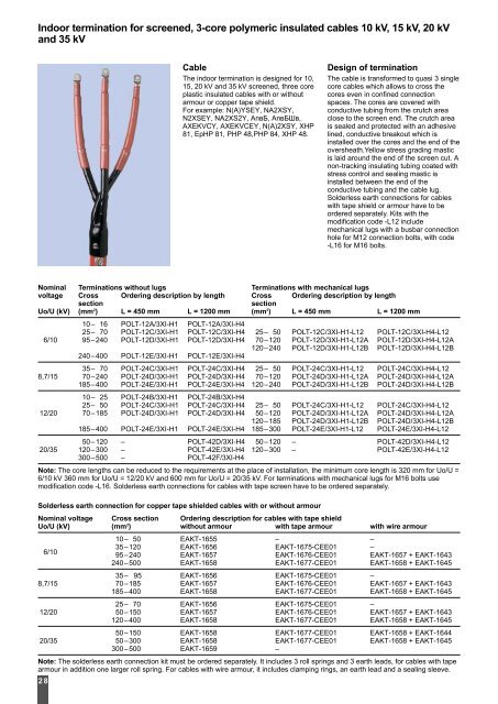
Indoor termination for screened, 3-core polymeric insulated cables 10 kV, 15 kV, 20 kV<br />
and 35 kV<br />
Nominal Terminations without lugs Terminations with mechanical lugs<br />
voltage Cross Ordering description by length Cross Ordering description by length<br />
section section<br />
Uo/U (kV) (mm2 ) L = 450 mm L = 1200 mm (mm2 ) L = 450 mm L = 1200 mm<br />
10– 16 POLT-12A/3XI-H1 POLT-12A/3XI-H4<br />
25– 70 POLT-12C/3XI-H1 POLT-12C/3XI-H4 25– 50 POLT-12C/3XI-H1-L12 POLT-12C/3XI-H4-L12<br />
6/10 95–240 POLT-12D/3XI-H1 POLT-12D/3XI-H4 70–120 POLT-12D/3XI-H1-L12APOLT-12D/3XI-H4-L12A<br />
120–240 POLT-12D/3XI-H1-L12B POLT-12D/3XI-H4-L12B<br />
240–400 POLT-12E/3XI-H1 POLT-12E/3XI-H4<br />
35– 70 POLT-24C/3XI-H1 POLT-24C/3XI-H4 25– 50 POLT-24C/3XI-H1-L12 POLT-24C/3XI-H4-L12<br />
8,7/15 70–240 POLT-24D/3XI-H1 POLT-24D/3XI-H4 70–120 POLT-24D/3XI-H1-L12APOLT-24D/3XI-H4-L12A<br />
185–400 POLT-24E/3XI-H1 POLT-24E/3XI-H4 120–240 POLT-24D/3XI-H1-L12B POLT-24D/3XI-H4-L12B<br />
10– 25 POLT-24B/3XI-H1 POLT-24B/3XI-H4<br />
25– 50 POLT-24C/3XI-H1 POLT-24C/3XI-H4 25– 50 POLT-24C/3XI-H1-L12 POLT-24C/3XI-H4-L12<br />
12/20 70–185 POLT-24D/3XI-H1 POLT-24D/3XI-H4 50–120 POLT-24D/3XI-H1-L12APOLT-24D/3XI-H4-L12A<br />
120–185 POLT-24D/3XI-H1-L12B POLT-24D/3XI-H4-L12B<br />
185–400 POLT-24E/3XI-H1 POLT-24E/3XI-H4 185–300 POLT-24E/3XI-H1-L12 POLT-24E/3XI-H4-L12<br />
50–120 – POLT-42D/3XI-H4 50–120 – POLT-42D/3XI-H4-L12<br />
20/35 120–300 – POLT-42E/3XI-H4 120–300 – POLT-42E/3XI-H4-L12<br />
300–500 – POLT-42F/3XI-H4<br />
Note: The core lengths can be reduced to the requirements at the place of installation, the minimum core length is 320 mm for Uo/U =<br />
6/10 kV 360 mm for Uo/U = 12/20 kV and 600 mm for Uo/U = 20/35 kV. For terminations with mechanical lugs for M16 bolts use<br />
modification code -L16. Solderless earth connections for cables with tape screen have to be ordered separately.<br />
Solderless earth connection for copper tape shielded cables with or without armour<br />
Nominal voltage Cross section Ordering description for cables with tape shield<br />
Uo/U (kV) (mm2 ) without armour with tape armour with wire armour<br />
10– 50 EAKT-1655 – –<br />
6/10<br />
35–120<br />
95–240<br />
EAKT-1656<br />
EAKT-1657<br />
EAKT-1675-CEE01<br />
EAKT-1676-CEE01<br />
–<br />
EAKT-1657 + EAKT-1643<br />
240–500 EAKT-1658 EAKT-1677-CEE01 EAKT-1658 + EAKT-1645<br />
35– 95 EAKT-1656 EAKT-1675-CEE01 –<br />
8,7/15 70–185 EAKT-1657 EAKT-1676-CEE01 EAKT-1657 + EAKT-1643<br />
185–400 EAKT-1658 EAKT-1677-CEE01 EAKT-1658 + EAKT-1645<br />
25– 70 EAKT-1656 EAKT-1675-CEE01 –<br />
12/20 50–150 EAKT-1657 EAKT-1676-CEE01 EAKT-1657 + EAKT-1643<br />
120–400 EAKT-1658 EAKT-1677-CEE01 EAKT-1658 + EAKT-1645<br />
50–150 EAKT-1658 EAKT-1677-CEE01 EAKT-1658 + EAKT-1644<br />
20/35 50–300 EAKT-1658 EAKT-1677-CEE01 EAKT-1658 + EAKT-1645<br />
300–500 EAKT-1659 –<br />
Note: The solderless earth connection kit must be ordered separately. It includes 3 roll springs and 3 earth leads, for cables with tape<br />
armour in addition one larger roll spring. For cables with wire armour, it includes clamping rings, an earth lead and a sealing sleeve.<br />
2 8<br />
<strong>Cable</strong><br />
The indoor termination is designed for 10,<br />
15, 20 kV and 35 kV screened, three core<br />
plastic insulated cables with or without<br />
armour or copper tape shield.<br />
For example: N(A)YSEY, NA2XSY,<br />
N2XSEY, NA2XS2Y, АпвБ, АпвБШв,<br />
AXEKVCY, AXEKVCEY, N(A)2XSY, XHP<br />
81, EpHP 81, PHP 48,PHP 84, XHP 48.<br />
Design of termination<br />
The cable is transformed to quasi 3 single<br />
core cables which allows to cross the<br />
cores even in confined connection<br />
spaces. The cores are covered with<br />
conductive tubing from the crutch area<br />
close to the screen end. The crutch area<br />
is sealed and protected with an adhesive<br />
lined, conductive breakout which is<br />
installed over the cores and the end of the<br />
oversheath.Yellow stress grading mastic<br />
is laid around the end of the screen cut. A<br />
non-tracking insulating tubing coated with<br />
stress control and sealing mastic is<br />
installed between the end of the<br />
conductive tubing and the cable lug.<br />
Solderless earth connections for cables<br />
with tape shield or armour have to be<br />
ordered separately. Kits with the<br />
modification code -L12 include<br />
mechanical lugs with a busbar connection<br />
hole for M12 connection bolts, with code<br />
-L16 for M16 bolts.